EP0664890B1 - Raumliche filterung von formation und kanal echosignale - Google Patents
Raumliche filterung von formation und kanal echosignale Download PDFInfo
- Publication number
- EP0664890B1 EP0664890B1 EP93924309A EP93924309A EP0664890B1 EP 0664890 B1 EP0664890 B1 EP 0664890B1 EP 93924309 A EP93924309 A EP 93924309A EP 93924309 A EP93924309 A EP 93924309A EP 0664890 B1 EP0664890 B1 EP 0664890B1
- Authority
- EP
- European Patent Office
- Prior art keywords
- casing
- borehole
- signal
- signal set
- spatial filter
- Prior art date
- Legal status (The legal status is an assumption and is not a legal conclusion. Google has not performed a legal analysis and makes no representation as to the accuracy of the status listed.)
- Expired - Lifetime
Links
Images





Classifications
-
- G—PHYSICS
- G01—MEASURING; TESTING
- G01V—GEOPHYSICS; GRAVITATIONAL MEASUREMENTS; DETECTING MASSES OR OBJECTS; TAGS
- G01V1/00—Seismology; Seismic or acoustic prospecting or detecting
- G01V1/40—Seismology; Seismic or acoustic prospecting or detecting specially adapted for well-logging
- G01V1/44—Seismology; Seismic or acoustic prospecting or detecting specially adapted for well-logging using generators and receivers in the same well
- G01V1/48—Processing data
- G01V1/50—Analysing data
Definitions
- the present invention relates to a method for hydraulic isolation determination of oilfield casings. More specifically, the interfaces between the various materials present in the borehole are interrogated using ultrasonic energies. The resulting signals are spatially filtered to reduce the sensitivity to the casing and increase the sensitivity of later (deeper) interfaces represented, for example, by formation reflections.
- a string of casing or pipe is set in a wellbore and a fill material referred to as cement is forced into the annulus between the casing and the earth formation.
- the primary purpose of the cement is to separate oil and gas producing layers from each other and from water bearing strata. If cement fails to provide isolation of one zone from another, fluids under pressure may migrate from one zone to another, reducing production efficiency. Migration of water, in particular, produces undesirable water cutting of a producing zone and can possibly render a well non-commercial. Also, migration of hydrocarbons into aquifers is environmentally and economically undesirable. It is critical to determine whether the cement is performing its function to hydraulically secure hydrocarbon reservoirs. The term "good cement" indicates the adequate separation of zones by the cement, preventing fluid migration between the zones.
- Cement failures occur in a variety of ways. For example, a complete absence of cement between the casing and the earth formation can occur. This is characterized as a gross cement failure and leads to rapid communication between zones intended to be isolated. Another type of failure arises when channeling occurs within the cement annulus between the casing and the formation. There are three commonly occurring types of channels. First, a channel which contacts the casing is referred to as a "near channel”. Second, a channel which does not contact the casing is referred to as a "far channel” or a "buried-channel". For a buried channel, the region between the channel and the casing is usually cement.
- a channel occupying the entire space between the casing and the formation is referred to as either a "full channel” or a “traditional channel”. All the channels described above are filled with fluids such as mud or gas and all are potential threats to hydraulic isolation.
- micro-annulus Another condition which occurs, but which is not generally viewed as a cement failure, is known as micro-annulus. This condition occurs when the cement that has filled the annulus is not properly bonded to the casing resulting in a very narrow fluid-filled annulus immediately outside the casing. This annulus is very small and does not affect fluid communication between layers, effectively preserving the hydraulic security function of the cement.
- a completed well includes a number of interfaces at the junctures of the differing materials within the wellbore.
- a first interface exists at the juncture of the fluid in the casing and the casing itself.
- the casing is referred to as a first material and is typically made of steel.
- a second interface is formed between the casing and a second material adjacent to the exterior of the casing. If cement is properly placed between the casing and the formation, providing hydraulic isolation, the second interface exists between the casing (first material) and the cement (second material). Further, a third interface exists between the cement and a third material which is the earth formation.
- Imperfect cementing operations can result in a variety of interface conditions.
- a channel contacting the casing results in the second interface being between the casing (first material) and a fluid (second material).
- the third interface is formed between a fluid (second material) and the earth formation (third material) where a full channel exists.
- the third interface is formed between a fluid (second material) and the cement (third material) where a near channel exists.
- a channel not contacting the casing results in the second interface being between the casing (first material) and the cement (second material) and the third interface being between the cement (second material) and a fluid (third material).
- Existence of a buried channel causes a potential lack of hydraulic isolation.
- the "head" of the received waveform is energy reflected from the inner surface of the casing. It is the earliest and highest amplitude portion of the waveform. It contains no information of materials beyond the casing.
- the decaying, resonant tail of the received waveform is predominantly energy which has resonated within the casing and, therefore, contains information about the casing itself and about the materials in direct contact with the casing (mud or cement).
- Energy reflecting from structures not contacting the casing, such as fluid-channels or the formation, are also contained within this tail, but are typically much less energetic than the dominant steel resonances. This makes the direct measurement of these later structures very difficult as the signal in the measurement window is largely controlled by changes in the casing (e.g., local thickness) or by changes in the casing/cement interface (e.g., local disbonds).
- any acoustic measurement technique used on a casing-cement-formation system will result in received energy which is dominated by the casing reflections.
- the reflections from typical, outer structures will be relatively weaker signals.
- US 5,072,388 describes a log analysis method which can be used to determine a relative condition of a lined casing within a geothermal well.
- the effect of unknown scale thickness on indicators of casing condition are removed by identifying an adjacent interfacial indicator within a window and axially aligning the adjacent indicator by shifting a data signal towards a reference indicator.
- US 4,283,953 describes techniques for broad band high frequency acoustic investigation of a subsurface formation.
- a range of acoustic frequencies are selected to produce detectable acoustic backscatter from grains within the formation.
- the backscatter is detected and a spectrum thereof produced and averaged.
- a parameter such as attenuation of backscatter is determined to provide an indication of granularity properties of the formation.
- EP 0395499 A describes a method for determining cement bond and casing thickness in a cased well from a reflected acoustic signal obtained by directing an acoustic pulse at a substantially normal incidence towards a radial sector of the wall of the casing.
- First and second time windows are defined and information in the first window is determined while normalising the information by information contained within the second window.
- the present invention provides a method for spatially filtering signals representing formation and channel echoes in a borehole environment obtained using any of a number of tools including, but not limited to USITM, CBLTM, CBTTM, VDLTM, and CETTM.
- the resulting signals are useful for determining hydraulic isolation in oilfield casings.
- Spatial filtering is performed upon a set of signals representing the entire volume of the annulus between the casing and the earth formation.
- the filtered signals are used to characterize such parameters as cement annulus thickness and formation rugosity, and to detect fluid channels.
- Interrogation of the wellbore is performed by directing acoustic energy pulses at azimuthal and depth intervals around the inside of the casing. Each pulse passes through the various materials present in the wellbore and the surrounding formation. Energy is reflected from the interfaces between the materials passing back through the materials and into the borehole where it is detected as a signal.
- the present technique includes advantages over previously known methods of examining the material outside the casing in a borehole environment. This is because while the known techniques for analyzing the material beyond the casing concentrate on characterizing the interface between the casing and the material just beyond the casing, the present technique instead characterizes channels formed between the material just outside the casing and the material beyond that.
- the invention modifies sets of signals obtained by transmitting acoustic energy pulses at azimuthal and depth intervals around the inside of the casing. Each signal comprises interface echoes which return to a receiver inside the casing. Each echo represents acoustic energy reflected from a specific set of one or more interfaces.
- the present invention filters the signals to select desired echoes and reject undesired echoes, and thus permits analysis of the borehole materials to determine whether channels exist between the first material (casing) and the earth formation.
- the basic advantage of a spatial filtering method in accordance with the present invention is that the signals are filtered to provide clear representation of a particular interface around the circumference of the borehole (azimuth) as well as a representation of an interface as a function of depth.
- the filtered signals indicate the quality of isolation achieved by the fill material or cement outside the casing. Additionally, since casing thickness can be easily measured, the present method provides an accurate measurement of a thickness of the second material.
- Another aspect of the present invention involves deconvolution. By deconvolving the results obtained in the above-described filtering techniques, the various borehole materials are more clearly indicated providing an accurate display of the interfaces and channels present in the borehole.
- Figure 1 is a cross-sectional diagram showing materials used in a completed borehole to achieve hydraulic isolation.
- a borehole 111 is cased with a first material 115, typically steel pipe. Outside and adjacent to first material 115 lies a second material.
- Second material is usually a fill material, commonly referred to as cement, which is pumped into the annulus 119 between casing 115 and earth formation 117. The cement hydrates to retain casing 115 rigidly in position. More importantly, it fills the annulus 119 between casing 115 and earth formation 117 sealing off the hydrocarbon strata from the other layers so that when casing 115 and the cement are subsequently perforated, the hydrocarbons enter directly into casing 115 and migration of fluids between adjacent formation layers is prevented.
- Fluid 121 usually in the form of mud, fills casing 115 and annulus 119 before cement placement.
- a first interface 123 exists along the juncture between fluid 121 (usually mud) and casing 115.
- second material in the form of cement completely fills the annulus 119 between casing 115 and earth formation 117.
- a second interface 125 is formed between casing 115 and cement.
- a third interface 127 emphasized by the bold line, exists at the juncture of cement and earth formation 117.
- fill material or cement does not always completely fill the space between casing 115 and earth formation 117.
- the first condition is shown along radial line R 1 .
- a near channel 129 exists between casing 115 and cement .
- second interface 125 existing between casing 115 and cement, it is formed between casing 115 and the fluid of near channel 129.
- the fluid of near channel 129 is the second material.
- third interface 127 existing between cement and earth formation 117, it is formed at the juncture of a fluid and cement.
- a full channel 133 is shown along radial line R2. Full channel 133 extends completely across the annulus to earth formation 117. As in the case of near channel 129, full channel 133 also has a second interface between first material 115 and a fluid. However, the third interface for full channel 133 is between a fluid and earth formation 117.
- the third condition occurs when a channel is formed in the space 119 between second material and earth formation 117. In this case, the channel does not contact first material 115.
- This condition is shown along radial line R 3 and is referred to as a buried channel 131.
- second interface 125 is formed between casing 115 and second material (cement), and third interface 127 is formed at the juncture of second material and the fluid of buried channel 131.
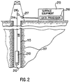
- Figure 2 is a schematic diagram of a logging operation.
- Tool or sonde 210 for acquiring acoustic data is located in borehole 111 penetrating earth formation 117.
- Sonde 210 is preferably lowered in the borehole by armored multiconductor cable 214 and slowly raised by surface equipment 215 over sheave wheel 216 while data measurements are recorded in azimuthal intervals by rotating transducer 212.
- the depth of the tool is measured by depth gauge 217 which measures cable displacement.
- Sonde 210 acquires acoustic data by emitting an acoustic pulse and detecting its return waveform.
- the sonde comprises at least one transducer.
- the transducer produces a pulse upon excitation.
- the pulse is directed into casing 115 and a transducer receives a resulting signal.
- the pulse interacts with all of the interfaces it encounters. This includes both inner and outer surfaces of the casing, both near and far edges of the cement annulus, any fluid channel contained within the cement, and the formation surface. Due to the typical acoustic impedances and dimensions of these materials, the return signal will largely represent interaction with the casing interfaces. Representation of more distant structures such as formation or channeling, is typically of significantly lesser amplitude.
- the transducers 212 are mounted to rotate azimuthally and transmit and receive acoustic energy at locations around the circumference of casing 115 as they rotate and at various depths as the tool is raised or lowered in the well.
- the depth can be analyzed by the sonde in situ , analyzed by data processor 218 at the surface, or stored, either in the sonde or at the site for analysis at a remote location.
- Figure 3A is a waveform V, obtained from an ultrasonic cement-evaluation measurement taken, for example with the apparatus shown in Fig. 2.
- V is divided into two main portions.
- One portion, CV shown in Fig. 3B represents the reflected energy which has interacted with a first interface 123 formed between casing 115 and fluid 121 and a second interface 125 formed between casing 115 and second material.
- the other portion, TIV shown in Fig. 3C represents echoes which have interacted once with third interface 127 located between second material and third material 117. Multiple interactions with third interface 127 and interactions with more distant interfaces are neglected. All of the waveforms are functions of time ( t ) and the location at which they are collected.
- the reflection from the third interface will vary spatially.
- TIV is different at every location, then the value of each location will appear with a factor of 1/N in the final average. If N is large, and the different TIVs do not add coherently, then the contribution of the TIVs to the average will be small enough to neglect.
- An approximation to the desired third interface echo is obtained by subtracting the average from the original: TIV ( t, ⁇ ,z ) ⁇ V ( t, ⁇ ,z ) - AV ( t )
- casings are not perfect, so the casing waveform does vary spatially (CV is CV ( t, ⁇ ,z )).
- W is not equal to zero only for some range in the ⁇ and z directions. W does not need to be uniform, in which case it will have an effective range which is less than its full range. For the approximation to be good, the effective range must be chosen large enough such that TIV ( t, ⁇ ,z ) varies considerably in that range and nearly cancels itself out in the average. Further, it must be small enough that CV ( t, ⁇ ,z ) is nearly constant over the effective range, so that the averaging does not effect it.
- This operation which can be viewed as subtraction of a local average from the data, or as convolution (*) with the kernel SF, is one example of a spatial filter to select for TIV which has strong spatial variations over a CV which does not.
- This convolutional filter is a linear filter; its output consists of weighted sums of its inputs, where the weights are predetermined and do not depend on the input. It is also possible to use nonlinear filters. For example, the weights may depend on the input, or the inputs may be raised to a power, or may appear as arguments of some transcendental function, etc., as one skilled in the art will recognize.
- the window-design criteria contain potentially conflicting requirements, they can be fulfilled.
- the geometry of the casing can be controlled much better than the geometry of the borehole or the position of the casing within the borehole. This is especially true in new casings, before corrosion has had time to occur, and in deviated holes where centralization and cementing is problematic. Therefore, the casing waveform varies spatially less than the third-interface waveform under many practical conditions.
- the shape determines whether all waveforms in the window receive the same weight, or whether more distant waveforms have more or less effect than nearer waveforms on the average.
- Fig. 4 is a top-view of a cased borehole 111.
- Casing 115 varies in thickness about its circumference.
- a spherically focused transducer 212 is mounted in sonde 210 (Fig. 2) and is situated in fluid 121 in borehole 111. Transducer 212 rotates azimuthally around the circumference of casing 115 generating and receiving signals, such as that of Fig. 3A as it rotates.
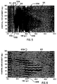
- Fig. 5 illustrates a signal set. Each signal is measured in terms of voltage as a function of time, from an individual azimuthal position obtained upon generating and receiving acoustic energy in accordance with the configuration of Fig. 4. Each individual signal is similar to the one shown in Fig. 3A. Fig. 5 permits identification of echoes from the various interfaces present in borehole 111.
- the region to the left of line 513 contains energy which has reverberated in casing 115.
- the frequency of reverberation is indicative of the thickness of casing 115.
- the region between line 513 and sinusoidally-shaped line 515, whose endpoints are 515A and 515B, is dominated by this energy which has reverberated in casing 115 without propagating beyond casing 115.
- the region to the right of (later than) line 515 is a mixture of energy which has reverberated in casing 115, but not propagated beyond the casing, and energy which has reflected from third interface 125 (Figs. 1, 4), and representing TIV.
- the energy to the left of line 515 is all from CV, while the energy to the right of line 515 is a mixture of CV and TIV.
- Echoes between lines 511 and 513 are substantially lined up vertically because the signals have been aligned. Echoes between lines 513 and 515 (second interface 125) line up with a slight curvature as a function of azimuth indicating that thickness of casing 115 changes as a function of azimuth. Casing 115 is thinnest at about 67°, and is thickest at about 247° (180° away). Finally, line 515 oscillates between about 15 ⁇ Sec and 38 ⁇ Sec indicating a great range of distances between transducer 212 and third interface 127 formed between second material and third material 117. Although the casing thickness is relatively constant around the circumference at a particular depth, casing 115 is eccentered within the cement. This causes a sinusoidal shaped onset (beginning) of energy received from third interface 127 between the cement and earth formation 117.
- Fig. 6 represents the same signals shown in Fig. 5 after spatial filtering has been performed.
- the spatial filtering operation greatly increases the clarity of the reflections from third interface 127 (TIV). In Fig. 6, this is represented by the region to the right of line 615, formed between points 615A and 615B, which substantially retains the third interface echoes while substantially removing casing reflections (CV).
- the sinusoidally shaped onset of echoes from the third interface between annulus 119 and earth formation 117 accurately indicates the distance between the casing and formation.
- Figs. 7A and 7B show a borehole configuration (7A) and a corresponding aligned and spatially filtered signal set representing casing 115 centered and cemented in borehole 111, with two buried channels 721A and 721B.
- the second type of third interface condition is a cement/channel interface. Echo 717 from a first channel is centered at approximately 90° and is about 35° wide. Echo 719 from a second channel is centered at approximately 180° and is about 50° wide. At their edges, these channels are nearly the same distance from the casing as the cement/formation interface. However, as points closer to their centers are considered, third interface 127 moves closer to the casing as is seen in Fig. 7A. The echoes from the cement/channel interfaces appear strong in Fig. 7B because they are strong functions of azimuth, and thus not removed by the spatial filter.
- the onsets of echoes from the cement/channel interfaces accurately indicate their geometry, being simultaneous with the onsets from the cement/formation echoes at their edges, and earlier toward the centers.
- the onsets of the cement/channel interfaces 717 and 719 form an "image" of the channels, and are important in evaluating the quality of the cement job.
- FIG. 8 A very simple deconvolution filter is shown in Fig. 8. When this filter is convolved with the signals in Fig. 3A and 3C, it yields the desirable results in Figs. 9 and 10, respectively.
- T 0 can be found in a number of ways, either from previously known information about casing thickness and the acoustic impedances of materials in the borehole, or from the data itself.
- R is approximately the decay ratio of a signal reverberating in the casing after one reverberation.
- casing thickness and second-material impedance as calculated for example, by the processing algorithm of the USITM tool.
- Many different forms of a deconvolution filter are possible, and there are many ways of determining their parameters (see Peacock, K.L. and Treitel, S., Productive Convolution Theory and Practice, Geophysics , 1969, Vol. 34, No. 2.).
- the Dirac impulse, ⁇ ⁇ which is a function of continuous time, must be approximated by some function of discrete time. The quality of the results depends on the quality of the approximation.
- V(t,q, z ) CIV(t,q,z ) + CRV(t,q,z) + TIV(t,q,z)
- CIV(t,q , z ) is the echo from the inner surface of the casing, which is essentially the high amplitude portion of CV ( t , q , z ) in Fig. 3B.
- CRV(t,q,z) is the casing resonance, which is essentially the later, low-amplitude portion of CV(t, q, z) in Fig. 3B.
- CIV(t, q, z ) and CRV(t, q, z) is CV(t, q, z ) , the casing echo discussed above.
- TIV(t, q, z ) is the third-interface echo.
- Deconvolution with the filter in Eq. (6) subtracts a scaled and shifted copy of the original signal from itself.
- the most important effect of deconvolution is to reduce the amplitude of CRV(t, q, z) as seen by comparing Figs. 3A and 9. Reducing the amplitude of the casing resonance generally improves the ability to examine the filtered version of TIV(t, q, z).
- Another important effect of deconvolution is to cause the peak of the filtered version of TIV(t, q, z) to occur near its onset, around 42 ⁇ s in Fig. 10, rather than growing in amplitude as it does in Fig. 3C. Detection of the onset is the easiest means of measuring the thickness of the second material, and peak detection or related algorithms tend to be more robust than threshold detection algorithms.
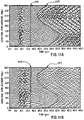
- Figure 11A shows a spatially filtered set of signals from an unfocused transducer in a borehole configured like that of Fig. 4.
- Fig. 11B shows the same signal set after deconvolution.
- Fig 11A there is remnant of the casing resonance between line 1111 and sinusoidally-shaped line 1113 than between line 1115 and sinusoidally-shaped line 1117 in Fig. 11 B.
- the echoes immediately after (to the right of) lines 1113 and 1117 are patterned similarly, the echoes in Fig 11A grow in amplitude at later times.
- echoes in Fig. 11B generally decrease in amplitude.
- the remnant of the reflection from the inner surface of the casing, to the left of line 1115 lasts longer due to deconvolution, than it does to the left of line 1111.
- Another aspect of the invention is its applicability to borehole measurements before hydration of fill material in the annulus between the casing and the earth formation. Such information may be useful for a number of applications including quality control of casing centralization before cement placement and/or after cement is placed but before hydration occurs. It should be understood that although the figures show aligned signal sets, it is not a requirement of the invention that the signals be aligned. In addition, the results of spatial filtering may be dependent on the spatial sampling rates and on the dynamic range of the digitized signals in the signal set. Therefore, the above description should not be taken as limiting the scope of the invention which is defined by the appended claims.
Landscapes
- Physics & Mathematics (AREA)
- Life Sciences & Earth Sciences (AREA)
- Remote Sensing (AREA)
- Acoustics & Sound (AREA)
- Environmental & Geological Engineering (AREA)
- Geology (AREA)
- Engineering & Computer Science (AREA)
- General Life Sciences & Earth Sciences (AREA)
- General Physics & Mathematics (AREA)
- Geophysics (AREA)
- Investigating Or Analyzing Materials By The Use Of Ultrasonic Waves (AREA)
- Geophysics And Detection Of Objects (AREA)
- Measurement And Recording Of Electrical Phenomena And Electrical Characteristics Of The Living Body (AREA)
- Ultra Sonic Daignosis Equipment (AREA)
- Networks Using Active Elements (AREA)
Claims (27)
- Ein Verfahren zum Charakterisieren von Grenzflächen, gebildet zwischen verschiedenen Materialien in der Umgebung eines ausgekleideten Bohrlochs, durch Filtern eines Satzes von Signalen, welche die verschiedenen Materialien repräsentieren, umfassend die Schritte:Einspeisen akustischer Energie in die Umgebung des ausgekleideten Bohrlochs von einem Wandler in dem Bohrloch;Empfangen von Signalen als eine Kollektion von Datenwerten einschließlich Echos, welche das Eintreffen von Grenzflächen, gebildet zwischen den verschiedenen Materialien, repräsentieren;Aufzeichnen jedes Signals in einem Signalsatz;Modifizieren von Datenwerten in einem Signal in dem Signalsatz zum Trennen eines ersten Echos von zumindest einem anderen Echo; undBereitstellen eines gefilterten Signalsatzes;dadurch gekennzeichnet, daß die empfangenen Signale zumindest zwei räumlich distinkte Signale umfassen, die in einem räumlichen Signalsatz aufgezeichnet werden, und daß ein räumliches Filter angewandt wird zum Modifizieren zumindest eines Datenwertes in einem ersten Signal in dem räumlichen Signalsatz und zumindest eines anderen Datenwertes in zumindest einem anderen Signal in dem räumlichen Signalsatz, um die Echos voneinander zu trennen.
- Das Verfahren nach Anspruch 1, bei dem das räumliche Filter ein nichtlineares Filter ist.
- Das Verfahren nach Anspruch 2, bei dem der gefilterte Signalsatz analysiert wird, um Grenzflächen zu charakterisieren, ausgebildet zwischen verschiedenen Materialien in dem Bohrloch, durch Bestimmen von Eintreffzeiten von Echos für ein bestimmtes Signal.
- Das Verfahren nach Anspruch 3, bei dem das Charakterisieren von Grenzflächen, gebildet zwischen verschiedenen Materialien in dem Bohrloch, das Bestimmen einer Dicke eines bestimmten Bohrlochmaterials umfaßt.
- Das Verfahren nach Anspruch 4, umfassend die Schritte:Messen einer Zeitverzögerung zwischen einem Echo von einer ersten Grenzfläche und einem Echo von einer dritten Grenzfläche;Subtrahieren einer Zeitverzögerung bekannter Zeit infolge einer Auskleidungsdicke; undGewinnen einer Zeitverzögerung, die indikativ ist für eine Dicke eines zweiten Materials.
- Das Verfahren nach Anspruch 3, bei dem das Charakterisieren von Grenzflächen, gebildet zwischen verschiedenen Materialien in dem Bohrloch, das Bestimmen einer Impedanz eines bestimmten Bohrlochmaterials umfaßt.
- Das Verfahren nach Anspruch 2, bei dem das räumliche Filter in einer azimuthalen Richtung angewandt wird.
- Das Verfahren nach Anspruch 2, bei dem das räumliche Filter in einer Tiefenrichtung angewandt wird.
- Das Verfahren nach Anspruch 2, bei dem das räumliche Filter sowohl in azimuthaler als auch in Tiefenrichtung angewandt wird.
- Das Verfahren nach Anspruch 2, bei dem das räumliche Filter auf zumindest einen anderen Datenpunkt in dem ersten Signal angewandt wird.
- Das Verfahren nach Anspruch 10, bei dem Rückfaltung auf jedes Signal in dem Signalsatz angewandt wird.
- Das Verfahren nach Anspruch 11, bei dem die Rückfaltung im wesentlichen gleichzeitig auf eine Mehrzahl von Signalen in dem Signalsatz angewandt wird.
- Das Verfahren nach Anspruch 2, bei dem das erste Echo Echos von Auskleidungsgrenzflächen umfaßt.
- Das Verfahren nach Anspruch 2, bei dem zumindest zwei andere Datenwerte in dem Signalsatz zusammen gemittelt werden zum Erhalten eines lokalen mittleren Filterwertes, der von dem mindestens einen Datenwert als räumliches Filter subtrahiert wird.
- Das Verfahren nach Anspruch 1, bei dem das räumliche Filter ein lineares Filter ist.
- Das Verfahren nach Anspruch 15, bei dem der gefilterte Signalsatz analysiert wird zum Charakterisieren von Grenzflächen, gebildet zwischen verschiedenen Materialien in dem Bohrloch, durch Bestimmen von Eintreffzeiten von Echos für ein bestimmtes Signal.
- Das Verfahren nach Anspruch 16, bei dem das Charakterisieren von Grenzflächen, gebildet zwischen verschiedenen Materialien in dem Bohrloch, das Bestimmen einer Dicke eines bestimmten Bohrlochmaterials umfaßt.
- Das Verfahren nach Anspruch 17, umfassend die Schritte:Messen einer Zeitverzögerung zwischen einem Echo von einer ersten Grenzfläche und einem Echo von einer dritten Grenzfläche;Subtrahieren einer Zeitverzögerung bekannter Zeit, beruhend auf einer Auskleidungsdicke; undGewinnen einer Zeitverzögerung, die indikativ ist für eine Dicke eines zweiten Materials.
- Das Verfahren nach Anspruch 16, bei dem das Charakterisieren von Grenzflächen, gebildet zwischen verschiedenen Materialien in dem Bohrloch, das Bestimmen einer Impedanz eines bestimmten Bohrlochmaterials umfaßt.
- Das Verfahren nach Anspruch 15, bei dem das räumliche Filter in einer azimuthalen Richtung angewandt wird.
- Das Verfahren nach Anspruch 15, bei dem das räumliche Filter in einer Tiefenrichtung angewandt wird.
- Das Verfahren nach Anspruch 15, bei dem das räumliche Filter sowohl in einer azimuthalen als auch in einer Tiefenrichtung angewandt wird.
- Das Verfahren nach Anspruch 15, bei dem das räumliche Filter auf mindestens einen anderen Datenpunkt von dem ersten Signal angewandt wird.
- Das Verfahren nach Anspruch 23, bei dem Rückfaltung angewandt wird auf jedes Signal in dem Signalsatz.
- Das Verfahren nach Anspruch 24, bei dem die Rückfaltung auf eine Mehrzahl von Signalen in dem Signalsatz im wesentlichen gleichzeitig angewandt wird.
- Das Verfahren nach Anspruch 15, bei dem das erste Echo Echos von Auskleidungsgrenzflächen umfaßt.
- Das Verfahren nach Anspruch 15, bei dem mindestens zwei andere Datenwerte in dem Signalsatz zusammen gemittelt werden zum Gewinnen eines lokalen mittleren Filterwertes, der von dem mindestens einen Datenwert als räumliches Filter subtrahiert wird.
Applications Claiming Priority (3)
| Application Number | Priority Date | Filing Date | Title |
|---|---|---|---|
| US960524 | 1992-10-13 | ||
| US07/960,524 US5274604A (en) | 1992-10-13 | 1992-10-13 | Method for spatially filtering signals representing formation and channel echoes in a borehole environment |
| PCT/US1993/009756 WO1994009387A1 (en) | 1992-10-13 | 1993-10-12 | Spatially filtering formation and channel echo signals |
Publications (2)
| Publication Number | Publication Date |
|---|---|
| EP0664890A1 EP0664890A1 (de) | 1995-08-02 |
| EP0664890B1 true EP0664890B1 (de) | 1996-07-03 |
Family
ID=25503282
Family Applications (1)
| Application Number | Title | Priority Date | Filing Date |
|---|---|---|---|
| EP93924309A Expired - Lifetime EP0664890B1 (de) | 1992-10-13 | 1993-10-12 | Raumliche filterung von formation und kanal echosignale |
Country Status (7)
| Country | Link |
|---|---|
| US (1) | US5274604A (de) |
| EP (1) | EP0664890B1 (de) |
| AU (1) | AU679193B2 (de) |
| CA (1) | CA2146980C (de) |
| DE (1) | DE69303492D1 (de) |
| NO (1) | NO306799B1 (de) |
| WO (1) | WO1994009387A1 (de) |
Families Citing this family (28)
| Publication number | Priority date | Publication date | Assignee | Title |
|---|---|---|---|---|
| FR2692931B1 (fr) * | 1992-06-25 | 1994-09-30 | Schlumberger Services Petrol | Procédé pour l'étude morphologique de formations géologiques traversées par un forage. |
| US5491668A (en) * | 1994-05-13 | 1996-02-13 | Western Atlas International, Inc. | Method for determining the thickness of a casing in a wellbore by signal processing pulse-echo data from an acoustic pulse-echo imaging tool |
| US6188643B1 (en) * | 1994-10-13 | 2001-02-13 | Schlumberger Technology Corporation | Method and apparatus for inspecting well bore casing |
| US5859811A (en) * | 1996-02-29 | 1999-01-12 | Schlumberger Technology Corporation | Method of analyzing waveforms |
| US5644550A (en) * | 1996-07-02 | 1997-07-01 | Western Atlas International, Inc. | Method for logging behind casing |
| US6041861A (en) * | 1997-12-17 | 2000-03-28 | Halliburton Energy Services, Inc. | Method to determine self-calibrated circumferential cased bond impedance |
| US20050128873A1 (en) * | 2003-12-16 | 2005-06-16 | Labry Kenneth J. | Acoustic device and method for determining interface integrity |
| DE602004024986D1 (de) * | 2004-09-13 | 2010-02-25 | Schlumberger Technology Bv | Verfahren zum Bestimmen der Impedanz von Materialien hinter der Bohrlochverrohrung |
| US7639562B2 (en) * | 2006-05-31 | 2009-12-29 | Baker Hughes Incorporated | Active noise cancellation through the use of magnetic coupling |
| AU2010358076B2 (en) | 2010-07-30 | 2013-10-10 | Halliburton Energy Services, Inc. | High resolution downhole imaging |
| EP2971490B1 (de) * | 2013-03-15 | 2017-04-26 | FMC Kongsberg Subsea AS | Verfahren zur bestimmung einer position einer wasser-/zementgrenze zwischen rohren in einem kohlenwasserstoffbohrloch |
| WO2014140363A2 (en) * | 2013-03-15 | 2014-09-18 | Fmc Kongsberg Subsea As | Method for determining a position of a water/cement boundary between pipes in a hydrocarbon well |
| EP2803815B1 (de) * | 2013-05-16 | 2020-02-12 | Services Petroliers Schlumberger | Verfahren zur datengesteuerten parametrischen Korrektur akustischer Zementbeurteilungsdaten |
| US10358905B2 (en) | 2014-01-13 | 2019-07-23 | Weatherford Technology Holdings, Llc | Ultrasonic logging methods and apparatus for measuring cement and casing properties using acoustic echoes |
| MX2017002735A (es) * | 2014-09-10 | 2017-10-20 | Halliburton Energy Services Inc | Flujo de trabajo multivariable para evaluacion y caracterizacion de revestimiento de cemento. |
| EP3175086B1 (de) * | 2014-09-10 | 2021-12-01 | Halliburton Energy Services, Inc. | Multivariabler arbeitsablauf für zementbeurteilung in mehreren rohrsträngen |
| US9835022B2 (en) | 2014-09-10 | 2017-12-05 | Halliburton Energy Services, Inc. | Multi-sensor workflow for evaluation of water flow in multiple casing strings with distributed sensors data |
| US10102315B2 (en) | 2014-12-08 | 2018-10-16 | University Of Washington | Advanced downhole waveform interpretation |
| CA2997209A1 (en) * | 2015-10-09 | 2017-04-13 | Halliburton Energy Services, Inc. | Hazard avoidance during well re-entry |
| EP3182167A1 (de) * | 2015-12-15 | 2017-06-21 | Services Pétroliers Schlumberger | Verfahren zur entrauschung von impulsechomessung mittels werkzeugreaktion vor kragen |
| EP3182173A1 (de) * | 2015-12-16 | 2017-06-21 | Services Pétroliers Schlumberger | Entfaltung von elektromagnetischer dickenmessung |
| US10156653B2 (en) * | 2015-12-18 | 2018-12-18 | Schlumberger Technology Corporation | Techniques for removing interface noise from acoustic log data |
| CA3058728C (en) * | 2017-06-08 | 2023-09-05 | Halliburton Energy Services, Inc. | Downhole ranging using spatially continuous constraints |
| AU2018338337A1 (en) * | 2017-09-22 | 2020-05-07 | Philip Teague | Method for using voxelated x-ray data to adaptively modify ultrasound inversion model geometry during cement evaluation |
| US10586340B2 (en) * | 2018-03-29 | 2020-03-10 | Schlumberger Technology Corporation | Coherent noise reduction in ultrasonic data |
| US10605943B2 (en) * | 2018-03-29 | 2020-03-31 | Schlumberger Technology Corporation | Coherent noise reduction in ultrasonic data |
| US11397081B2 (en) * | 2019-07-02 | 2022-07-26 | Baker Hughes Oilfield Operations Llc | Method and apparatus for determining a tubular thickness using a pulse echo waveform signal |
| US20250354480A1 (en) * | 2024-05-20 | 2025-11-20 | Baker Hughes Oilfield Operations Llc | Casing thickness determination from pulse-echo ultrasonic measurements |
Family Cites Families (8)
| Publication number | Priority date | Publication date | Assignee | Title |
|---|---|---|---|---|
| US4283953A (en) * | 1978-10-30 | 1981-08-18 | Schlumberger Technology Corporation | Method and apparatus for determining a granularity property of a subsurface formation around a borehole |
| NO172359C (no) * | 1986-09-30 | 1993-07-07 | Schlumberger Ltd | Fremgangsmaate og apparat for bestemmelse av egenskaper hos materiale bak foringsroer i broennhull |
| US4796237A (en) * | 1987-01-28 | 1989-01-03 | Amoco Corporation | Method for acoustic reverberation removal |
| US4885722A (en) * | 1988-01-19 | 1989-12-05 | Mobil Oil Corporation | Method for removing low-frequency noise from records with data impulse |
| US4928269A (en) * | 1988-10-28 | 1990-05-22 | Schlumberger Technology Corporation | Determining impedance of material behind a casing in a borehole |
| FR2646513B1 (fr) * | 1989-04-26 | 1991-09-20 | Schlumberger Prospection | Procede et dispositif de diagraphie pour l'inspection acoustique d'un sondage muni d'un tubage |
| US4951266A (en) * | 1989-04-28 | 1990-08-21 | Schlumberger Technology Corporation | Method of filtering sonic well logging data |
| US5072388A (en) * | 1990-01-31 | 1991-12-10 | Union Oil Company Of California | Lined casing inspection method |
-
1992
- 1992-10-13 US US07/960,524 patent/US5274604A/en not_active Expired - Lifetime
-
1993
- 1993-10-12 WO PCT/US1993/009756 patent/WO1994009387A1/en not_active Ceased
- 1993-10-12 AU AU54042/94A patent/AU679193B2/en not_active Ceased
- 1993-10-12 DE DE69303492T patent/DE69303492D1/de not_active Expired - Lifetime
- 1993-10-12 CA CA002146980A patent/CA2146980C/en not_active Expired - Lifetime
- 1993-10-12 EP EP93924309A patent/EP0664890B1/de not_active Expired - Lifetime
-
1995
- 1995-04-10 NO NO951402A patent/NO306799B1/no not_active IP Right Cessation
Also Published As
| Publication number | Publication date |
|---|---|
| WO1994009387A1 (en) | 1994-04-28 |
| NO951402D0 (no) | 1995-04-10 |
| US5274604A (en) | 1993-12-28 |
| NO306799B1 (no) | 1999-12-20 |
| AU5404294A (en) | 1994-05-09 |
| AU679193B2 (en) | 1997-06-26 |
| NO951402L (no) | 1995-06-13 |
| CA2146980A1 (en) | 1994-04-28 |
| EP0664890A1 (de) | 1995-08-02 |
| CA2146980C (en) | 1998-12-29 |
| DE69303492D1 (de) | 1996-08-08 |
Similar Documents
| Publication | Publication Date | Title |
|---|---|---|
| EP0664890B1 (de) | Raumliche filterung von formation und kanal echosignale | |
| US5859811A (en) | Method of analyzing waveforms | |
| US6018496A (en) | Method and apparatus for hydraulic isolation determination | |
| US4928269A (en) | Determining impedance of material behind a casing in a borehole | |
| EP1047935B1 (de) | Verfahren und vorrichtung zur abbildung von verrohrten bohrlöchern mit biegewellen | |
| Hayrnan et al. | High-resolution cementation and corrosion imaging by ultrasound | |
| US4685092A (en) | Method and apparatus for the acoustic inspection of a borehole fitted with casing | |
| EP0395499B1 (de) | Verfahren und Gerät zur akustischen Untersuchung der in einem Bohrloch zementierten Verrohrung | |
| US11726225B2 (en) | Detection and evaluation of ultrasonic subsurface backscatter | |
| US9903973B2 (en) | Systems and methods for removing coherent noise in log data | |
| EP3743598B1 (de) | Vorrichtung, system und verfahren zur bestimmung der qualität von barriere und material hinter mehreren rohren in einem bohrloch | |
| EP0549419B1 (de) | Verfahren und Gerät zur hydraulischen Isolationsbestimmung | |
| GB2308190A (en) | Acoustic reflection borehole logging apparatus | |
| Cabella et al. | Tubing eccentricity evaluation using the third interface echo | |
| Sinha et al. | Applications of sonics and ultrasonics in geophysical prospecting | |
| CA3088619C (en) | A tool, system and a method for determining barrier and material quality behind multiple tubulars in a hydrocarbon wellbore | |
| Zheng | Dispersion Asymptotic Analysis and its Applications in Acoustic Logging | |
| Singh et al. | Advanced Cement Mapping Techniques in Complex Wellbore Environment Aiding Informed Workover Decisions |
Legal Events
| Date | Code | Title | Description |
|---|---|---|---|
| PUAI | Public reference made under article 153(3) epc to a published international application that has entered the european phase |
Free format text: ORIGINAL CODE: 0009012 |
|
| 17P | Request for examination filed |
Effective date: 19950419 |
|
| AK | Designated contracting states |
Kind code of ref document: A1 Designated state(s): DE DK FR GB IT NL |
|
| 17Q | First examination report despatched |
Effective date: 19951005 |
|
| GRAH | Despatch of communication of intention to grant a patent |
Free format text: ORIGINAL CODE: EPIDOS IGRA |
|
| GRAH | Despatch of communication of intention to grant a patent |
Free format text: ORIGINAL CODE: EPIDOS IGRA |
|
| GRAA | (expected) grant |
Free format text: ORIGINAL CODE: 0009210 |
|
| AK | Designated contracting states |
Kind code of ref document: B1 Designated state(s): DE DK FR GB IT NL |
|
| PG25 | Lapsed in a contracting state [announced via postgrant information from national office to epo] |
Ref country code: NL Free format text: LAPSE BECAUSE OF FAILURE TO SUBMIT A TRANSLATION OF THE DESCRIPTION OR TO PAY THE FEE WITHIN THE PRESCRIBED TIME-LIMIT Effective date: 19960703 Ref country code: IT Free format text: LAPSE BECAUSE OF FAILURE TO SUBMIT A TRANSLATION OF THE DESCRIPTION OR TO PAY THE FEE WITHIN THE PRE;WARNING: LAPSES OF ITALIAN PATENTS WITH EFFECTIVE DATE BEFORE 2007 MAY HAVE OCCURRED AT ANY TIME BEFORE 2007. THE CORRECT EFFECTIVE DATE MAY BE DIFFERENT FROM THE ONE RECORDED.SCRIBED TIME-LIMIT Effective date: 19960703 Ref country code: DK Effective date: 19960703 |
|
| REF | Corresponds to: |
Ref document number: 69303492 Country of ref document: DE Date of ref document: 19960808 |
|
| PG25 | Lapsed in a contracting state [announced via postgrant information from national office to epo] |
Ref country code: DE Effective date: 19961005 |
|
| ET | Fr: translation filed | ||
| NLV1 | Nl: lapsed or annulled due to failure to fulfill the requirements of art. 29p and 29m of the patents act | ||
| REG | Reference to a national code |
Ref country code: FR Ref legal event code: CD |
|
| REG | Reference to a national code |
Ref country code: FR Ref legal event code: CD |
|
| PLBE | No opposition filed within time limit |
Free format text: ORIGINAL CODE: 0009261 |
|
| STAA | Information on the status of an ep patent application or granted ep patent |
Free format text: STATUS: NO OPPOSITION FILED WITHIN TIME LIMIT |
|
| 26N | No opposition filed | ||
| REG | Reference to a national code |
Ref country code: GB Ref legal event code: IF02 |
|
| PGFP | Annual fee paid to national office [announced via postgrant information from national office to epo] |
Ref country code: FR Payment date: 20101020 Year of fee payment: 18 |
|
| REG | Reference to a national code |
Ref country code: FR Ref legal event code: ST Effective date: 20120629 |
|
| PG25 | Lapsed in a contracting state [announced via postgrant information from national office to epo] |
Ref country code: FR Free format text: LAPSE BECAUSE OF NON-PAYMENT OF DUE FEES Effective date: 20111102 |
|
| PGFP | Annual fee paid to national office [announced via postgrant information from national office to epo] |
Ref country code: GB Payment date: 20121010 Year of fee payment: 20 |
|
| REG | Reference to a national code |
Ref country code: GB Ref legal event code: PE20 Expiry date: 20131011 |
|
| PG25 | Lapsed in a contracting state [announced via postgrant information from national office to epo] |
Ref country code: GB Free format text: LAPSE BECAUSE OF EXPIRATION OF PROTECTION Effective date: 20131011 |