EP0664984B1 - Coulisse de tiroir séquentielle ou similaire - Google Patents
Coulisse de tiroir séquentielle ou similaire Download PDFInfo
- Publication number
- EP0664984B1 EP0664984B1 EP94120260A EP94120260A EP0664984B1 EP 0664984 B1 EP0664984 B1 EP 0664984B1 EP 94120260 A EP94120260 A EP 94120260A EP 94120260 A EP94120260 A EP 94120260A EP 0664984 B1 EP0664984 B1 EP 0664984B1
- Authority
- EP
- European Patent Office
- Prior art keywords
- rail
- pull
- out mechanism
- mechanism according
- drawer
- Prior art date
- Legal status (The legal status is an assumption and is not a legal conclusion. Google has not performed a legal analysis and makes no representation as to the accuracy of the status listed.)
- Expired - Lifetime
Links
- 230000008878 coupling Effects 0.000 claims description 43
- 238000010168 coupling process Methods 0.000 claims description 43
- 238000005859 coupling reaction Methods 0.000 claims description 43
- 238000003780 insertion Methods 0.000 claims description 8
- 230000037431 insertion Effects 0.000 claims description 8
- 230000006835 compression Effects 0.000 description 6
- 238000007906 compression Methods 0.000 description 6
- 238000010586 diagram Methods 0.000 description 6
- 235000008331 Pinus X rigitaeda Nutrition 0.000 description 3
- 235000011613 Pinus brutia Nutrition 0.000 description 3
- 241000018646 Pinus brutia Species 0.000 description 3
- 239000000463 material Substances 0.000 description 3
- 229910000831 Steel Inorganic materials 0.000 description 2
- 230000000694 effects Effects 0.000 description 2
- 239000010959 steel Substances 0.000 description 2
- 239000006096 absorbing agent Substances 0.000 description 1
- 230000009471 action Effects 0.000 description 1
- 229910052782 aluminium Inorganic materials 0.000 description 1
- XAGFODPZIPBFFR-UHFFFAOYSA-N aluminium Chemical compound [Al] XAGFODPZIPBFFR-UHFFFAOYSA-N 0.000 description 1
- 230000008859 change Effects 0.000 description 1
- 210000001520 comb Anatomy 0.000 description 1
- 238000013016 damping Methods 0.000 description 1
- 229910052751 metal Inorganic materials 0.000 description 1
- 239000002184 metal Substances 0.000 description 1
- 238000000034 method Methods 0.000 description 1
- 230000008569 process Effects 0.000 description 1
- 230000035939 shock Effects 0.000 description 1
- 229910001220 stainless steel Inorganic materials 0.000 description 1
- 239000010935 stainless steel Substances 0.000 description 1
- 230000007704 transition Effects 0.000 description 1
Images






Classifications
-
- A—HUMAN NECESSITIES
- A47—FURNITURE; DOMESTIC ARTICLES OR APPLIANCES; COFFEE MILLS; SPICE MILLS; SUCTION CLEANERS IN GENERAL
- A47B—TABLES; DESKS; OFFICE FURNITURE; CABINETS; DRAWERS; GENERAL DETAILS OF FURNITURE
- A47B88/00—Drawers for tables, cabinets or like furniture; Guides for drawers
- A47B88/40—Sliding drawers; Slides or guides therefor
- A47B88/49—Sliding drawers; Slides or guides therefor with double extensible guides or parts
- A47B88/493—Sliding drawers; Slides or guides therefor with double extensible guides or parts with rollers, ball bearings, wheels, or the like
-
- A—HUMAN NECESSITIES
- A47—FURNITURE; DOMESTIC ARTICLES OR APPLIANCES; COFFEE MILLS; SPICE MILLS; SUCTION CLEANERS IN GENERAL
- A47B—TABLES; DESKS; OFFICE FURNITURE; CABINETS; DRAWERS; GENERAL DETAILS OF FURNITURE
- A47B88/00—Drawers for tables, cabinets or like furniture; Guides for drawers
- A47B88/40—Sliding drawers; Slides or guides therefor
- A47B88/453—Actuated drawers
- A47B88/46—Actuated drawers operated by mechanically-stored energy, e.g. by springs
- A47B88/467—Actuated drawers operated by mechanically-stored energy, e.g. by springs self-closing
-
- A—HUMAN NECESSITIES
- A47—FURNITURE; DOMESTIC ARTICLES OR APPLIANCES; COFFEE MILLS; SPICE MILLS; SUCTION CLEANERS IN GENERAL
- A47B—TABLES; DESKS; OFFICE FURNITURE; CABINETS; DRAWERS; GENERAL DETAILS OF FURNITURE
- A47B2210/00—General construction of drawers, guides and guide devices
- A47B2210/0002—Guide construction for drawers
- A47B2210/0064—Guide sequencing or synchronisation
- A47B2210/007—Three slide synchronisation
-
- A—HUMAN NECESSITIES
- A47—FURNITURE; DOMESTIC ARTICLES OR APPLIANCES; COFFEE MILLS; SPICE MILLS; SUCTION CLEANERS IN GENERAL
- A47B—TABLES; DESKS; OFFICE FURNITURE; CABINETS; DRAWERS; GENERAL DETAILS OF FURNITURE
- A47B2210/00—General construction of drawers, guides and guide devices
- A47B2210/0002—Guide construction for drawers
- A47B2210/0064—Guide sequencing or synchronisation
- A47B2210/0072—Coordinating mechanisms for sequential drawer slides, e.g. by cable
-
- A—HUMAN NECESSITIES
- A47—FURNITURE; DOMESTIC ARTICLES OR APPLIANCES; COFFEE MILLS; SPICE MILLS; SUCTION CLEANERS IN GENERAL
- A47B—TABLES; DESKS; OFFICE FURNITURE; CABINETS; DRAWERS; GENERAL DETAILS OF FURNITURE
- A47B2210/00—General construction of drawers, guides and guide devices
- A47B2210/0002—Guide construction for drawers
- A47B2210/0064—Guide sequencing or synchronisation
- A47B2210/0083—Drawer symmetric movement on opposite telescopic rails
-
- A—HUMAN NECESSITIES
- A47—FURNITURE; DOMESTIC ARTICLES OR APPLIANCES; COFFEE MILLS; SPICE MILLS; SUCTION CLEANERS IN GENERAL
- A47B—TABLES; DESKS; OFFICE FURNITURE; CABINETS; DRAWERS; GENERAL DETAILS OF FURNITURE
- A47B2210/00—General construction of drawers, guides and guide devices
- A47B2210/02—Drawers with hollow lateral walls in two parts
Definitions
- the invention relates to a differential pull-out for drawers or the like one to be attached to a furniture body, one on the drawer pull-out rail to be fastened and a middle rail arranged between them on each side of the drawer, with the weight of the drawers between the Rails by means of rollers or the like. Is transmitted, and preferably at the front and a deflection roller is arranged at the rear end of the middle rail, and a Control cable, which is attached to the mounting rail and on the pull-out rail, via the Deflection rollers is guided.
- Such a differential extract is known from DE-A-40 19 124.
- the Control cable is attached to the mounting rail on the one hand and on the other hand has one Coupling element with which it can be detachably suspended in the pull-out rail.
- a particularly precise guidance of the middle rail is achieved by a control cable, which is attached to the mounting rail and the pull-out rail and that on both Sides of the middle rail run and over at the front and rear end Band guides of the middle rail is guided.
- a control cable which is attached to the mounting rail and the pull-out rail and that on both Sides of the middle rail run and over at the front and rear end Band guides of the middle rail is guided.
- Such a differential extract is in DE-A-29 04 116.
- the object of the invention is a controller for a To create differential extension with a timing belt where the pull-out rails are slightly off the center rails can be lifted off. Another job of Invention is to create the condition that the control cable can be tensioned and that the front panel is pressed firmly against the side walls of the furniture.
- control cable has two free ends that in at known manner by a receiving part and a Insert part which have rack-like profiles, can be coupled, the receiving part or the insertion part can be coupled to the mounting rail and that two more with each other via rack-like profiles detachable coupling parts are provided, of which one as a cable coupling part attached to the control cable and one as attached to the pull-out rail Rail coupling part is executed.
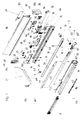
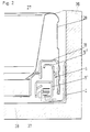
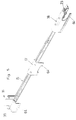
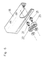
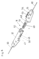
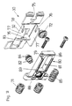
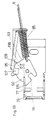
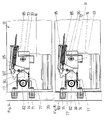
- Fig. 1 shows diagrammatically and pulled apart the parts of the differential pull-out and the drawer frame; 2 shows a vertical section through one side of the drawer; 3 shows a diagram the middle rail; 4 shows a vertical section through the drawer frame and the differential pull-out in the rear area; 5 shows a Diagram of a pull-out rail with adapter; 6 shows graphically and pulled apart the rear Casters and the rear adapter; 7 shows a diagram of the control cable and the two clutches; 8 shows a diagram of the cable coupling; Fig. 9 shows a diagram of the clutch that the Control cable connects to the pull-out rail, the Engaging from the front is indicated; 10 shows a same diagram as FIG.
- FIG. 9 shows diagrammatically and pulled apart a fastening device for the Front panel;
- Fig. 12 shows the same view as that Fig. 11 of a further embodiment of a fastening device for the front panel and the fig. 13 to 15 show side views of the fastening device according to Fig. 12.
- the drawer is supported by the two metal drawer frames 28 the front panel 39 the drawer base 38 and the rear wall 27 is formed.
- Adapters 16, 17, 18, which are attached to the pull-out rail 15, are welded to it, for example.
- the mounting rail 2 is in the usual way a fastening web 40 on the body side wall 36 attached.
- the drawer bottom 38 lies on a horizontal web 41 of the pull-out rail 15.
- In the horizontal bridge 41 are from the horizontal web 41 expressible rag 42 with pine cone profile, which in a groove or the like. of the drawer base 38 can be pressed in are and so the drawer bottom 38 on the pull-out rail Anchor 15.
- the middle rail 5 has a lower profile 5 'in which there is a carriage 3, in which rollers are stored.
- the middle rail 5 is therefore in relation to the mounting rail 2 on the rollers stored in the carriage 3 guided.
- the middle rail 5 is partially with an upper U-shaped profile 5 ''.
- the catwalks 43, 44 of this profile 5 ′′ run the rollers 22, 23 from the rear adapter 18 of the pull-out rail 15 are stored.
- the catwalk 45 of the pull-out rail 15 runs on the lower profile 5 'of the central rail 5 stored roller 6 from.
- the middle rail 5 has a front and a rear Pulley 9 for the control cable 10 on the Rope pulleys 9 of the central rail 5 is mounted.
- the control cable 10 for example by a wire or Plastic rope is formed, has a snapper-like Rope clutch 8 on.
- the cable coupling 8 exists from two coupling parts, namely a receiving part 12 and a plug-in part 13 with the rope ends of the control cable 10 are connected.
- the recording part 12 is designed as a housing. He points inside two rack-like profiles 46. The sidewalls are provided with openings 47 which the housing of the receiving part 12 has a certain elasticity to lend.
- the insertion part 13 has a finger-like projecting web 48, which also with rack-like Profiles 49 is provided with the rack-like Profiles 46 of the receiving part 12 correspond. The web 48 is in the housing of the receiving part 12 can be inserted until the control cable 10 is tensioned is.
- the teeth 50, 51 of the rack-like Profiles 46, 49 are like pine cones and face each other trained to insert the Web 48 of the insertion part 13 in the housing of the receiving part 12 to facilitate.
- Receiving part 12 is provided with a U-shaped recess 52.
- the insertion part 13 has a lateral hook 53 with which it enters an opening 14 in the mounting rail 2 is insertable. The insertion part 13 is thus over the Hook 53 can be anchored to the mounting rail 2.
- a special coupling is also provided.
- This consists of an outer Rail coupling part 19 and an inner cable coupling part 11.
- the outer rail coupling part 19 is on the pull-out rail 15 by means of screws or rivets 20, which protrude through mounting holes. He includes the inner cable coupling part 11 like pliers.
- the inner cable coupling part 11 is torpedo-shaped and in a trough-shaped recess 55 of the outer rail coupling part 19 depressible. It is a slit-like Opening 120 is provided, which is located on the both ends expanded circularly. This will make the Elasticity of the plastic Rail coupling part 19 increased.
- the teeth 57 of the rack-like profile 56 are ring-shaped.
- the cross section of the Teeth 57 is either pine cone-like or the cross-section corresponds to an isosceles triangle. On teeth 57 may be rounded on the outer edge.
- the cable coupling part 11 is, as from the figures of the Drawings can be seen, approximately cylindrical or Torpedo-shaped and points on both sides a frustoconical end portion 58.
- 19 can connect to each other the rail coupling part 19, as shown in FIG. 9, pushed from the front onto the cable coupling part 11 or, as shown in Fig.
- a roller 6 At the front end of the lower profile 5 'of the middle rail 5 is a roller 6 by means of a rent 7 stored on tabs 59. On the roller 6 runs Catwalk 45 from the pull-out rail 15.
- Three adapters 16, 17, 18 are attached to the running rail 15. At the rearmost adapter 18 are two rollers 22, 23 supported by rivets 21. The rollers 22, 23 are guided in the upper profile 5 ′′ of the central rail 5 and are inside the adapter 18. They store behind each other.
- the front roller 22 is narrower than the rear one Roller 23 and is based on the process of Drawer on the web 43 of the upper profile 5 '' of the middle rail 5 from.
- the web 44 of the profile 5 '' of the central rail 5 is U-shaped executed with a lateral limiting web 60. Between this boundary web 60 and the vertical web 61, the top with the same slope as that Limiting web 60 runs, the roller 23 is full guided. This ensures lateral guidance of the pull-out rail 15 and thus the drawer is guaranteed. Since the roller 22 on the lower horizontal web 43rd supports and the roller 23 on the upper horizontal web 44, it happens while pulling out or pushing in the drawer does not change the direction of rotation of the Casters 22, 23 and thus a quiet run Drawer scored.
- a headstock 4 made of plastic material attached.
- the headstock 4 has an opening 62, in which the roller 6 is mounted.
- the roller 6 rests on a rivet 7, which is held in flanges 67 is.
- the headstock 4, which is the front end of the lower Profile 5 'of the central rail 5 engages with provided a rail web 63, which has a straight section 63 'and a front, bent downward Section 63 ''.
- the drawer frames 28 are double-walled with one outer wall 65 and an inner wall 66 executed.
- the outer wall 65 has one at its lower edge hook-like inward, retaining bracket 67 angled at the top with which it fits into the holding webs 64 of the adapters 16, 17, 18 can be attached.
- the inner wall 66 has a horizontal web 68, the one with the drawer installed on the drawer bottom 38 rests and a vertical side web 69, the side abuts the drawer bottom 38.
- the transition from Horizontal web 68 to the inner wall 66 is rounded.
- drawer frames 28 neither with the adapters 16, 17, 18, still welded to the pull-out rail 15 or is grooved, drawer frames can be made any material hooked into the adapter 16, 17, 18 starting with plastic frames over aluminum frames to steel frames from one Stainless steel material.
- the furniture manufacturer is therefore given the opportunity given, also very different in price Drawers with the differential extract according to the invention equip.
- the foremost adapter 16 has a holding plate 70 provided on which a support member 32, 33 of a fastening device 30, 31 screwable for the front panel 39 is.
- the front panel 39 when assembling the drawer on the dowels 71 of the front panel attachment 30 pressed.
- the fastening device 30 is entirely on the pull-out rail 15 mounted.
- front panel attachment 31 is a holding part 34 attached to the front panel 39 and the support part 33 is attached to the holding plate 70 by means of a screw 72 attached.
- Both the support part 33 of the fastening device 31 and the support part 32 of the fastening device 30 is with a lateral guide wall 73 provided on a corresponding guide wall 74 of the holding plate 70 abuts.
- the support part 32 of the fastening device 30 has a slot 75 open to the rear through which the Fastening screw 72 protrudes into a nut thread 76 can be screwed into the holding plate 70.
- the fastening device 30 has a holding part 80 on, with dowels 71 on the front panel 39 is attached.
- the support part 32 which consists of a Sheet steel is stamped, has a tab 76 which protrudes at right angles from the support member 32.
- Above and below the support part 32 has a horizontal web 77 each with a slot 78 open to the rear. In the Slots 78, pins 79 of the holding part 80 are guided.
- the holding part 80 is provided with a recess 81.
- In the holding part 80 there is an adjusting screw 82 for the side adjustment of the front panel 39 stored. At mounted fitting protrudes the upper edge 83 of the support member 32 in an annular groove 84 of the adjusting screw 82, so that by turning the adjusting screw 82 of the holding part 81 moved laterally with respect to the support member 32 becomes.
- the fastening device 30 When the fastening device 30 is mounted, it projects Flange 76 of the support member 32 in the recess 81 of the Holding part 80.
- a compression spring 85 is mounted in the recess 81 and is supported on the one hand on the web 86 of the Holding part 80 and on the other hand on the tab 76 of the supporting part 32 from. By the compression spring 6, the holding part 80 pushed backwards and thus the front panel 39 on the front edges of the drawer frames 28 are drawn.
- the outer wall 65 of the front panel 28 is in the area the fastening device 30, 33 with a recess 87 provide access to tools on the fastener 30, 33 allows.
- the recess 87 is covered by a removable cover plate 29.
- the holding part 80 by means of a press ram that fits into the recess 81 engages and rests on the web 89 of the holding part 80, pushed something out of the drawer frame 28,
- the stop surface 88 is just in front of the end face the drawer frame 28.
- the front panel 39 on the dowels 71 of the holding part 80 be pressed. Is the front panel 39 on the dowels 71 of the holding part 80 is anchored, the ram pulled out of the recess 81 and the compression spring 85 presses the holding part 80 so far into the drawer frame 28 that the front panel 39 is full on the face the drawer frame 17 rests.
- the fastening device 31 has a support part 33 on, which in turn by means of a screw 72 on the holding plate 70 of the adapter 16 is attached.
- a rocker arm 90 is mounted on the Support part 33.
- the supporting part 33 again has an angled tab 76 at the back, on which the spring 85 is supported.
- the angled tab 76 is provided with a cross slot 91, through protrudes a rod 92 which carries the spring 85 and the directly applied to the rocker arm 90.
- the support part 33 is by means of the screw 72 which by a vertical slot 93 protrudes in the support member 32 and the can be screwed into the holding plate 70.
- the tilt segment 90 has an upper notch 93 and a lower notch 94.
- the locking bolt is located above the rocker arm 90 95, which is punched out at its rear end by means of a Slit 96 is stored on the rod 92 and the has a locking web 97 at the front which, when fastened Front panel 39 in the notch 93 of the rocker arm 90 snaps into place.
- the holding part 34 is directly on the front panel 39 attached.
- the adjusting screw 82 is located in it the side adjustment.
- the support part 32 has an upper and a lower Horizontal web 77, between which the holding part 34th can be inserted.
- On the webs 77 is a side plate 98 plugged into the pins 99 of the webs 77 protrude.
- the support part 33 and the side plate 98 have Punch holes 101 through which the pin 102 protrudes, the forms the axis of the tilting segment 90.
- the holding part 34 is provided with a hook 100.
- the tilt segment 90 is provided with a cross slot 108.
- the locking bolt 95 has a lateral web 107, which laterally overlaps the tilting segment 90. If the front panel 39 is now to be removed from the drawer frame 28 will be solved, a Phillips screwdriver will be in introduced the Phillips 108. This will make the Locking bar 95 raised because the screwdriver on the side bar 107 strikes. At the same time, the locking flange 97 lifted out of the notch 93 of the rocker arm 90 and the rocker arm 90 is thus free. Well now the rocker arm 90 when the Phillips screwdriver in the Phillips protrudes, rotating clockwise, causing the holding part 34 is released.
- the holding part 34 can also have a coupling part 103 be connected for a front panel.
- the rearmost adapter 18 carries a coupling part 25 for the rear wall 27.
- the coupling part 25 is with pin 105 provided in the punched holes 106 of angled Tabs 107 of the rear wall 27 protrude.
- the coupling part 25 points downward cantilevered, preferably resilient hook 108 on the hooks on adapter 18 when the coupling part is fitted.
- the rear wall 27 is still with a lower horizontal web 109 provided on which the drawer bottom 38 lies on.
Landscapes
- Engineering & Computer Science (AREA)
- Mechanical Engineering (AREA)
- Drawers Of Furniture (AREA)
Claims (13)
- Mécanisme de sortie différentiel pour tiroirs ou analogues comportant un rail porteur (2) à fixer sur un corps de meuble, un rail de sortie (15) à fixer sur le tiroir et un rail intermédiaire (5) disposé à chaque côté du tiroir, le poids des tiroirs entre les rails (2, 5, 15) étant transmis au moyen de galets de roulement ou analogues, et un galet de renvoi (9) étant disposé de préférence à l'extrémité avant comme à l'extrémité arrière du rail intermédiaire (5), et un câble de commande (10), qui est fixé sur le rail porteur (2) et sur le rail de sortie (15), étant guidé par l'intermédiaire des galets de renvoi (9), caractérisé en ce que le câble de commande (10) présente deux extrémités libres qui peuvent être couplées de manière connue par une pièce de réception (12) et une pièce à emboítement (13) qui présentent des profils (46, 49) en crémaillère, la pièce de réception (12) ou la pièce à emboítement (13) pouvant être couplée au rail porteur (2), et qu'il est prévu deux autres pièces d'accouplement pouvant être couplées entre elles par l'intermédiaire de profils en crémaillère, dont l'une est réalisée sous la forme d'une pièce d'accouplement de câble (11) fixée sur le câble de commande (10) et l'autre sous la forme d'une pièce d'accouplement de rail (19) fixée sur le rail de sortie (15).
- Mécanisme de sortie différentiel selon la revendication 1, la pièce à emboítement (13) présentant une traverse (48) saillante avec au moins le profil (49) en crémaillère, qui peut être emboítée dans la pièce de réception (12), caractérisé en ce que la pièce de réception (12) comporte un boítier avec une ouverture d'emboítement et deux perçages (47) sur des parois opposées, le profil (46) en crémaillère étant réalisé sur au moins une paroi du boítier.
- Mécanisme de sortie différentiel selon la revendication 2, caractérisé en ce que le boítier de la pièce de réception (12) est pourvu à son extrémité d'emboítement d'un évidement (52) en forme de U.
- Mécanisme de sortie différentiel selon une des revendications 1 à 3, caractérisé en ce que la pièce à emboítement (13) comporte un crochet (53) latéral qui peut être introduit dans un trou découpé (14) dans le rail porteur (2).
- Mécanisme de sortie différentiel selon la revendication 4, caractérisé en ce que des embouts de guidage (54), qui font saillie dans le trou découpé (14), sont disposés de part et d'autre du crochet (53).
- Mécanisme de sortie différentiel selon la revendication 1, caractérisé en ce que la pièce d'accouplement de câble (11) est cylindrique et les dents du profil (56) en crémaillère sont circulaires.
- Mécanisme de sortie différentiel selon la revendication 6, caractérisé en ce que la pièce d'accouplement de câble (11) est en forme de tronc de cône à ses deux extrémités.
- Mécanisme de sortie différentiel selon la revendication 6, caractérisé en ce que la pièce d'accouplement de rail (19) présente un évidement (55) en forme de cuvette dans lequel peut être enfoncée la pièce d'accouplement de câble (11).
- Mécanisme de sortie différentiel selon la revendication 6, caractérisé en ce que les dents (57) du profil (56) en crémaillère décrivent en coupe transversale un profil en pomme de pin ou un triangle isocèle.
- Mécanisme de sortie différentiel selon la revendication 6 ou 9, caractérisé en ce que les dents (57) sont arrondies en section transversale.
- Mécanisme de sortie différentiel selon la revendication 8, caractérisé en ce que le fond de l'évidement (55) en forme de cuvette comporte un ou plusieurs perçages (120).
- Mécanisme de sortie différentiel selon la revendication 8, caractérisé en ce que la pièce d'accouplement de câble (11) peut être enfoncée par le bas dans l'évidement (55) en forme de cuvette de la pièce d'accouplement de rail (19).
- Mécanisme de sortie différentiel selon une des revendications 1 à 12, caractérisé en ce qu'un dispositif d'introduction (1) connu en soi pour le tiroir est disposé sur le rail porteur (2) ou sur le rail de sortie (15), lequel dispositif d'introduction comprend un entraíneur (121) sollicité par ressort qui peut se déplacer dans une glissière linéaire et peut être bloqué aux deux extrémités de la glissière et que le rail intermédiaire (5) comporte une tige ou analogue sur laquelle a prise l'entraíneur (121) dans la zone d'entrée arrière du mécanisme de sortie différentiel.
Applications Claiming Priority (3)
| Application Number | Priority Date | Filing Date | Title |
|---|---|---|---|
| AT75/94 | 1994-01-17 | ||
| AT7594 | 1994-01-17 | ||
| AT0007594A AT401715B (de) | 1994-01-17 | 1994-01-17 | Differentialauszug für schubladen |
Publications (3)
| Publication Number | Publication Date |
|---|---|
| EP0664984A2 EP0664984A2 (fr) | 1995-08-02 |
| EP0664984A3 EP0664984A3 (fr) | 1997-02-05 |
| EP0664984B1 true EP0664984B1 (fr) | 2000-03-22 |
Family
ID=3480868
Family Applications (1)
| Application Number | Title | Priority Date | Filing Date |
|---|---|---|---|
| EP94120260A Expired - Lifetime EP0664984B1 (fr) | 1994-01-17 | 1994-12-21 | Coulisse de tiroir séquentielle ou similaire |
Country Status (7)
| Country | Link |
|---|---|
| US (1) | US5564807A (fr) |
| EP (1) | EP0664984B1 (fr) |
| JP (1) | JP2791753B2 (fr) |
| AT (2) | AT401715B (fr) |
| CA (1) | CA2140212A1 (fr) |
| DE (1) | DE59409231D1 (fr) |
| ES (1) | ES2144482T3 (fr) |
Cited By (3)
| Publication number | Priority date | Publication date | Assignee | Title |
|---|---|---|---|---|
| DE202008014042U1 (de) | 2008-10-22 | 2010-03-11 | Paul Hettich Gmbh & Co. Kg | Auszugsführung für ein Möbelteil |
| CN101511225B (zh) * | 2006-09-08 | 2013-11-27 | 保罗黑蒂希有限及两合公司 | 抽屉 |
| WO2026041722A1 (fr) | 2024-08-20 | 2026-02-26 | Peka-Metall Ag | Dispositif d'extraction synchronisée |
Families Citing this family (43)
| Publication number | Priority date | Publication date | Assignee | Title |
|---|---|---|---|---|
| ATA34396A (de) * | 1996-02-26 | 1998-10-15 | Blum Gmbh Julius | Ausziehführungsgarnitur für schubladen |
| US5876103A (en) * | 1996-06-05 | 1999-03-02 | Grass America, Inc. | Self-positioning cabinet rail for a drawer guide |
| US5722749A (en) * | 1996-06-05 | 1998-03-03 | Grass America, Inc. | Self-positioning cabinet rail for a drawer guide |
| NL1003665C2 (nl) * | 1996-07-23 | 1998-01-28 | Thomas Regout B V | Overuittrekbare diferentiële ladegeleider. |
| CH690813A5 (de) * | 1996-07-26 | 2001-01-31 | Blum Gmbh Julius | Vollauszugsführung für Schubladen. |
| AT407002B (de) * | 1997-04-01 | 2000-11-27 | Blum Gmbh Julius | Ausziehführungsgarnitur für schubladen |
| US6273534B1 (en) | 1999-11-05 | 2001-08-14 | Spacesaver Corporation | Shelving accessory mounting system for a cabinet assembly |
| ITMC20000049A1 (it) * | 2000-06-06 | 2001-12-06 | Compagnucci Spa | Componente polivalente per cesti metallici scorrevoli, collocati all'interno di mobili. |
| US6619771B2 (en) | 2001-12-06 | 2003-09-16 | Grass America, Inc. | Self-positioning cabinet rail for a drawer guide |
| DE20209416U1 (de) * | 2002-06-17 | 2003-10-30 | Alfit AG, Götzis | Anordnung für die Verbindung einer Schubladenzarge mit dem Boden einer Schublade |
| US7077488B2 (en) * | 2003-05-13 | 2006-07-18 | Grass America Inc. | Drawer closing mechanism |
| ATE526850T1 (de) * | 2003-05-13 | 2011-10-15 | Grass Gmbh | Frontalverriegelungsvorrichtung für das lösbare ineingriffbringen einer schublade in einem schubladenschieber |
| WO2006037419A1 (fr) * | 2004-09-30 | 2006-04-13 | Lautenschlaeger Horst | Tiroir de meuble |
| DE102005007001A1 (de) * | 2005-02-16 | 2006-08-17 | Lautenschläger, Horst | Einrichtung zur Aufnahme einer Schublade |
| US20060226748A1 (en) * | 2005-04-08 | 2006-10-12 | Merillat Industries, Llc | Drawer guide support bracket |
| CN101330850B (zh) * | 2005-12-15 | 2012-05-23 | 尤利乌斯·布卢姆有限公司 | 带有至少一个第一家具部件和一个第二家具部件的家具 |
| DE202007001783U1 (de) * | 2006-09-08 | 2008-01-10 | Paul Hettich Gmbh & Co. Kg | Verbindungseinrichtung an einem Schubkasten |
| DE202007001782U1 (de) * | 2006-09-08 | 2008-01-10 | Paul Hettich Gmbh & Co. Kg | Schubkasten |
| DE102007005948A1 (de) * | 2007-02-06 | 2008-08-07 | BSH Bosch und Siemens Hausgeräte GmbH | Kältegerät mit Teleskopauszug |
| AT505208B1 (de) * | 2007-04-23 | 2011-08-15 | Blum Gmbh Julius | Antrieb mit einem zugmittel und einer kupplung für ein bewegbares möbelteil |
| AT505207B1 (de) * | 2007-04-23 | 2011-08-15 | Blum Gmbh Julius | Einzugsvorrichtung für ein bewegbares möbelteil |
| GB2472959B (en) * | 2008-08-07 | 2013-04-10 | Accuride Int Inc | A synchronizing/stabilizing system and self moving mechanism for drawer applications |
| MY151706A (en) * | 2009-08-12 | 2014-06-30 | Harn Marketing Sdn Bhd | Drawer assembly |
| TW201117701A (en) * | 2009-11-03 | 2011-05-16 | Inventec Corp | Rail device and server |
| TW201117702A (en) * | 2009-11-04 | 2011-05-16 | Inventec Corp | Rail apparatus and server |
| DE102010060583A1 (de) * | 2010-11-16 | 2012-05-16 | Paul Hettich Gmbh & Co. Kg | Auszugsführung für ein Auszugsteil eines Möbels |
| DE102010060720A1 (de) * | 2010-11-22 | 2012-05-24 | Paul Hettich Gmbh & Co. Kg | Trageinrichtung zur Festlegung einer Frontblende |
| AT510018B1 (de) * | 2010-11-23 | 2012-01-15 | Blum Gmbh Julius | Vorrichtung zur anbringung eines funktionsteiles an einer schiene einer schubladenausziehführung |
| AT511417B1 (de) | 2011-04-27 | 2018-08-15 | Blum Gmbh Julius | Schubladenseitenwand mit einer innenwand und einer aussenwand |
| US8876232B2 (en) | 2011-10-27 | 2014-11-04 | Rsi Home Products Management, Inc. | Drawer glide mechanism |
| US12193567B2 (en) | 2012-03-02 | 2025-01-14 | American Woodmark Management Company | Drawer glide mechanism |
| AT15549U1 (de) * | 2012-08-31 | 2017-12-15 | Blum Gmbh Julius | Vorrichtung zum Einziehen oder Ausstoßen eines beweglich gelagerten Möbelteils |
| US8764135B1 (en) * | 2013-03-18 | 2014-07-01 | Nan Juen International Co., Ltd. | Linking mechanism |
| DE102013113672A1 (de) * | 2013-06-14 | 2014-12-18 | Paul Hettich Gmbh & Co. Kg | Auszugssystem |
| CN103504836B (zh) * | 2013-08-30 | 2016-04-06 | 伍志勇 | 抽屉 |
| US9375084B2 (en) | 2014-05-09 | 2016-06-28 | Rsi Home Products Management, Inc. | Drawer glide mechanism |
| DE202014104929U1 (de) * | 2014-10-16 | 2016-01-19 | Grass Gmbh | Zarge für eine Schublade mit einem Zargenkörper sowie Schublade und Möbel mit einer Schublade |
| DE102016111857B4 (de) * | 2016-06-29 | 2025-01-30 | Paul Hettich Gmbh & Co. Kg | Verfahren zur Montage eines Schubelementes und Bausatz zur verschiebbaren Lagerung eines Schubelementes, Möbel und Haushaltsgerät |
| CN108078254A (zh) * | 2016-11-22 | 2018-05-29 | 世塑有限公司 | 抽屉同步构件 |
| AT17935U1 (de) | 2017-08-17 | 2023-08-15 | Blum Gmbh Julius | Schubladenausziehführung |
| WO2019074271A1 (fr) * | 2017-10-12 | 2019-04-18 | (주)세고스 | Dispositif de coulissement |
| AT520822B1 (de) * | 2018-02-01 | 2019-08-15 | Blum Gmbh Julius | Schubladenseitenwand |
| DE202020107093U1 (de) * | 2020-12-09 | 2022-03-10 | Grass Gmbh | Möbelschublade |
Family Cites Families (19)
| Publication number | Priority date | Publication date | Assignee | Title |
|---|---|---|---|---|
| US2267043A (en) * | 1939-12-22 | 1941-12-23 | Owen D Premo | Pulley slide |
| GB660567A (en) * | 1947-05-22 | 1951-11-07 | William Lawrence & Company Ltd | Improvements in or relating to collapsible or knock-down furniture |
| US3078129A (en) * | 1960-06-22 | 1963-02-19 | Otto A Beeck | Band controlled extension slide |
| US3545833A (en) * | 1969-02-14 | 1970-12-08 | Instrument Systems Corp | Progressive slide assembly |
| US3687505A (en) * | 1971-06-11 | 1972-08-29 | Fall Herbert S | Slide with synchronizing cable drive |
| US3722964A (en) * | 1971-07-07 | 1973-03-27 | Oxford Pendaflex Corp | Extensible drawer support |
| US4025138A (en) * | 1975-02-20 | 1977-05-24 | Halle Industries Inc. | Progressive slide assemblies |
| US3980364A (en) * | 1975-06-04 | 1976-09-14 | Amerock Corporation | Roller bracket assembly for drawers |
| US4199200A (en) * | 1978-08-29 | 1980-04-22 | Amerock Corporation | Roller bracket assembly for drawers |
| DE2844850A1 (de) * | 1978-10-14 | 1980-04-30 | Grass Alfred Metallwaren | Fuehrungsschiene fuer schubladen mit einstellanordnung |
| DE2904116A1 (de) * | 1979-02-03 | 1980-08-07 | Standard Praezision Gmbh | Teleskopschiene |
| DE3335700A1 (de) * | 1983-10-01 | 1985-04-11 | Günter 7144 Asperg Grötzinger | Keilriemen |
| JPH0617347Y2 (ja) * | 1984-07-24 | 1994-05-02 | 北川工業株式会社 | 板材保持具 |
| DE4019124C2 (de) * | 1990-06-15 | 1994-06-01 | Grass Ag | Vollauszug |
| AT401851B (de) * | 1991-01-21 | 1996-12-27 | Blum Gmbh Julius | Beschlag |
| US5275064A (en) * | 1992-06-12 | 1994-01-04 | General Devices Co., Inc. | Extensible platform with cable drive system |
| DE4226812B4 (de) * | 1992-08-13 | 2004-10-21 | Grass Gmbh | Schubladenführung mit Vollauszug und Zugmittel |
| AT401713B (de) * | 1993-06-29 | 1996-11-25 | Blum Gmbh Julius | Differentialauszug für schubladen od. dgl. |
| ES2124437T3 (es) * | 1994-01-17 | 1999-02-01 | Blum Gmbh Julius | Cajon. |
-
1994
- 1994-01-17 AT AT0007594A patent/AT401715B/de not_active IP Right Cessation
- 1994-12-21 DE DE59409231T patent/DE59409231D1/de not_active Expired - Lifetime
- 1994-12-21 AT AT94120260T patent/ATE190814T1/de not_active IP Right Cessation
- 1994-12-21 EP EP94120260A patent/EP0664984B1/fr not_active Expired - Lifetime
- 1994-12-21 ES ES94120260T patent/ES2144482T3/es not_active Expired - Lifetime
-
1995
- 1995-01-12 JP JP7018845A patent/JP2791753B2/ja not_active Expired - Fee Related
- 1995-01-13 CA CA002140212A patent/CA2140212A1/fr not_active Abandoned
- 1995-01-13 US US08/372,373 patent/US5564807A/en not_active Expired - Fee Related
Cited By (3)
| Publication number | Priority date | Publication date | Assignee | Title |
|---|---|---|---|---|
| CN101511225B (zh) * | 2006-09-08 | 2013-11-27 | 保罗黑蒂希有限及两合公司 | 抽屉 |
| DE202008014042U1 (de) | 2008-10-22 | 2010-03-11 | Paul Hettich Gmbh & Co. Kg | Auszugsführung für ein Möbelteil |
| WO2026041722A1 (fr) | 2024-08-20 | 2026-02-26 | Peka-Metall Ag | Dispositif d'extraction synchronisée |
Also Published As
| Publication number | Publication date |
|---|---|
| JPH07213359A (ja) | 1995-08-15 |
| US5564807A (en) | 1996-10-15 |
| CA2140212A1 (fr) | 1995-07-18 |
| ES2144482T3 (es) | 2000-06-16 |
| ATA7594A (de) | 1996-04-15 |
| DE59409231D1 (de) | 2000-04-27 |
| ATE190814T1 (de) | 2000-04-15 |
| EP0664984A3 (fr) | 1997-02-05 |
| JP2791753B2 (ja) | 1998-08-27 |
| EP0664984A2 (fr) | 1995-08-02 |
| AT401715B (de) | 1996-11-25 |
Similar Documents
| Publication | Publication Date | Title |
|---|---|---|
| EP0664984A2 (fr) | Coulisse de tiroir séquentielle ou similaire | |
| EP0267477B1 (fr) | Dispositif de fixation de parois avant ajustables pour tiroirs | |
| AT404664B (de) | Vorrichtung zur befestigung der frontblende einer schublade an schubladenzargen | |
| EP0636327B1 (fr) | Dispositif pour fixer le panneau avant de tiroir sur les parois latérales | |
| EP0740917B1 (fr) | Dispositif pour fixer le panneau avant de tiroir, en particulier tiroir à double paroi, sur les parois latérales | |
| EP0581325B1 (fr) | Dispositif de fixation pour un rail de tiroir | |
| AT406181B (de) | Befestigungsvorrichtung für die befestigung mehrerer möbelbeschläge an einem möbelteil | |
| AT505177B1 (de) | Schublade mit schubladenunterteilung | |
| DE3832701A1 (de) | Befestigungsanordnung fuer die fuehrungsschiene einer ausziehfuehrung | |
| AT401714B (de) | Differentialauszug für schubladen od. dgl. | |
| AT398516B (de) | Schubkastenauszug | |
| EP1093735B1 (fr) | Glissière pour guidage de tiroirs avec dispositif de fixation et de réglage en hauteur | |
| DE9204845U1 (de) | Montagebeschlag für Schubladen | |
| DE2948627C2 (de) | Vorrichtung zum einstellbaren Befestigen einer Frontplatte an einem ausziehbaren Möbelteil | |
| DE69503828T2 (de) | Blokiervorrichtung für eine Verlängerung Bezüglich eines Möbelstückes, und Möbelstück damit Ausgestattet | |
| EP0736660B1 (fr) | Seuil de porte | |
| AT400796B (de) | Schubladenbausatz | |
| DE19707741A1 (de) | Möbelscharnier | |
| EP0809956A2 (fr) | Dispositif à tiroirs pour un élément coulissant, encastrable dans une unité d'armoire | |
| DE19852330C2 (de) | Haushaltsgerät mit einer Gerätetür und Mitteln zur Anbringung eines Türblattes an der Gerätetür und Verfahren zur Anbringung eines Türblattes an der Gerätetür eines Haushaltsgerätes | |
| EP0133707A2 (fr) | Armoire à chaussures, à rayons réglables en hauteur | |
| EP1518482A2 (fr) | Dispositif de suspension pour un placard le long d'un mur | |
| EP0702916B1 (fr) | Elément de tiroir d'ameublement | |
| AT410162B (de) | Vorrichtung zur stabilisierung des laufverhaltens einer in einem möbelkorpus verfahrbaren schublade | |
| AT398263B (de) | Auszugschiene mit einer integrierten seitenzarge |
Legal Events
| Date | Code | Title | Description |
|---|---|---|---|
| PUAI | Public reference made under article 153(3) epc to a published international application that has entered the european phase |
Free format text: ORIGINAL CODE: 0009012 |
|
| AK | Designated contracting states |
Kind code of ref document: A2 Designated state(s): AT CH DE ES FR GB IT LI |
|
| PUAL | Search report despatched |
Free format text: ORIGINAL CODE: 0009013 |
|
| AK | Designated contracting states |
Kind code of ref document: A3 Designated state(s): AT CH DE ES FR GB IT LI |
|
| 17P | Request for examination filed |
Effective date: 19970521 |
|
| 17Q | First examination report despatched |
Effective date: 19980313 |
|
| GRAG | Despatch of communication of intention to grant |
Free format text: ORIGINAL CODE: EPIDOS AGRA |
|
| GRAG | Despatch of communication of intention to grant |
Free format text: ORIGINAL CODE: EPIDOS AGRA |
|
| GRAH | Despatch of communication of intention to grant a patent |
Free format text: ORIGINAL CODE: EPIDOS IGRA |
|
| GRAH | Despatch of communication of intention to grant a patent |
Free format text: ORIGINAL CODE: EPIDOS IGRA |
|
| GRAA | (expected) grant |
Free format text: ORIGINAL CODE: 0009210 |
|
| AK | Designated contracting states |
Kind code of ref document: B1 Designated state(s): AT CH DE ES FR GB IT LI |
|
| REF | Corresponds to: |
Ref document number: 190814 Country of ref document: AT Date of ref document: 20000415 Kind code of ref document: T |
|
| REG | Reference to a national code |
Ref country code: CH Ref legal event code: EP |
|
| REF | Corresponds to: |
Ref document number: 59409231 Country of ref document: DE Date of ref document: 20000427 |
|
| ITF | It: translation for a ep patent filed | ||
| REG | Reference to a national code |
Ref country code: CH Ref legal event code: NV Representative=s name: ISLER & PEDRAZZINI AG |
|
| GBT | Gb: translation of ep patent filed (gb section 77(6)(a)/1977) |
Effective date: 20000515 |
|
| REG | Reference to a national code |
Ref country code: ES Ref legal event code: FG2A Ref document number: 2144482 Country of ref document: ES Kind code of ref document: T3 |
|
| ET | Fr: translation filed | ||
| PG25 | Lapsed in a contracting state [announced via postgrant information from national office to epo] |
Ref country code: AT Free format text: LAPSE BECAUSE OF NON-PAYMENT OF DUE FEES Effective date: 20001221 |
|
| PLBE | No opposition filed within time limit |
Free format text: ORIGINAL CODE: 0009261 |
|
| STAA | Information on the status of an ep patent application or granted ep patent |
Free format text: STATUS: NO OPPOSITION FILED WITHIN TIME LIMIT |
|
| 26N | No opposition filed | ||
| PGFP | Annual fee paid to national office [announced via postgrant information from national office to epo] |
Ref country code: CH Payment date: 20011217 Year of fee payment: 8 |
|
| PGFP | Annual fee paid to national office [announced via postgrant information from national office to epo] |
Ref country code: FR Payment date: 20011218 Year of fee payment: 8 |
|
| PGFP | Annual fee paid to national office [announced via postgrant information from national office to epo] |
Ref country code: GB Payment date: 20011219 Year of fee payment: 8 |
|
| REG | Reference to a national code |
Ref country code: GB Ref legal event code: IF02 |
|
| PGFP | Annual fee paid to national office [announced via postgrant information from national office to epo] |
Ref country code: ES Payment date: 20021212 Year of fee payment: 9 |
|
| PG25 | Lapsed in a contracting state [announced via postgrant information from national office to epo] |
Ref country code: GB Free format text: LAPSE BECAUSE OF NON-PAYMENT OF DUE FEES Effective date: 20021221 |
|
| PG25 | Lapsed in a contracting state [announced via postgrant information from national office to epo] |
Ref country code: LI Free format text: LAPSE BECAUSE OF NON-PAYMENT OF DUE FEES Effective date: 20021231 Ref country code: CH Free format text: LAPSE BECAUSE OF NON-PAYMENT OF DUE FEES Effective date: 20021231 |
|
| GBPC | Gb: european patent ceased through non-payment of renewal fee |
Effective date: 20021221 |
|
| REG | Reference to a national code |
Ref country code: CH Ref legal event code: PL |
|
| PG25 | Lapsed in a contracting state [announced via postgrant information from national office to epo] |
Ref country code: FR Free format text: LAPSE BECAUSE OF NON-PAYMENT OF DUE FEES Effective date: 20030901 |
|
| REG | Reference to a national code |
Ref country code: FR Ref legal event code: ST |
|
| PG25 | Lapsed in a contracting state [announced via postgrant information from national office to epo] |
Ref country code: ES Free format text: LAPSE BECAUSE OF NON-PAYMENT OF DUE FEES Effective date: 20031222 |
|
| REG | Reference to a national code |
Ref country code: ES Ref legal event code: FD2A Effective date: 20031222 |
|
| PG25 | Lapsed in a contracting state [announced via postgrant information from national office to epo] |
Ref country code: IT Free format text: LAPSE BECAUSE OF NON-PAYMENT OF DUE FEES;WARNING: LAPSES OF ITALIAN PATENTS WITH EFFECTIVE DATE BEFORE 2007 MAY HAVE OCCURRED AT ANY TIME BEFORE 2007. THE CORRECT EFFECTIVE DATE MAY BE DIFFERENT FROM THE ONE RECORDED. Effective date: 20051221 |
|
| PGFP | Annual fee paid to national office [announced via postgrant information from national office to epo] |
Ref country code: DE Payment date: 20140228 Year of fee payment: 20 |
|
| REG | Reference to a national code |
Ref country code: DE Ref legal event code: R071 Ref document number: 59409231 Country of ref document: DE |
|
| REG | Reference to a national code |
Ref country code: DE Ref legal event code: R071 Ref document number: 59409231 Country of ref document: DE |