EP0665352A1 - Verriegelbares, mechanisches Schloss - Google Patents
Verriegelbares, mechanisches Schloss Download PDFInfo
- Publication number
- EP0665352A1 EP0665352A1 EP95300391A EP95300391A EP0665352A1 EP 0665352 A1 EP0665352 A1 EP 0665352A1 EP 95300391 A EP95300391 A EP 95300391A EP 95300391 A EP95300391 A EP 95300391A EP 0665352 A1 EP0665352 A1 EP 0665352A1
- Authority
- EP
- European Patent Office
- Prior art keywords
- lever
- cam
- barrel
- housing
- lock
- Prior art date
- Legal status (The legal status is an assumption and is not a legal conclusion. Google has not performed a legal analysis and makes no representation as to the accuracy of the status listed.)
- Granted
Links
- 230000007935 neutral effect Effects 0.000 claims abstract description 19
- 238000003780 insertion Methods 0.000 claims abstract description 6
- 230000037431 insertion Effects 0.000 claims abstract description 6
- 230000000694 effects Effects 0.000 abstract description 4
- 230000000903 blocking effect Effects 0.000 description 12
- 210000000078 claw Anatomy 0.000 description 10
- 230000000881 depressing effect Effects 0.000 description 2
- 238000010276 construction Methods 0.000 description 1
- 239000002184 metal Substances 0.000 description 1
- 230000004048 modification Effects 0.000 description 1
- 238000012986 modification Methods 0.000 description 1
Images

Classifications
-
- E—FIXED CONSTRUCTIONS
- E05—LOCKS; KEYS; WINDOW OR DOOR FITTINGS; SAFES
- E05B—LOCKS; ACCESSORIES THEREFOR; HANDCUFFS
- E05B77/00—Vehicle locks characterised by special functions or purposes
- E05B77/22—Functions related to actuation of locks from the passenger compartment of the vehicle
- E05B77/24—Functions related to actuation of locks from the passenger compartment of the vehicle preventing use of an inner door handle, sill button, lock knob or the like
- E05B77/28—Functions related to actuation of locks from the passenger compartment of the vehicle preventing use of an inner door handle, sill button, lock knob or the like for anti-theft purposes, e.g. double-locking or super-locking
- E05B77/283—Functions related to actuation of locks from the passenger compartment of the vehicle preventing use of an inner door handle, sill button, lock knob or the like for anti-theft purposes, e.g. double-locking or super-locking initiated by hand actuation, e.g. by using a mechanical key
-
- E—FIXED CONSTRUCTIONS
- E05—LOCKS; KEYS; WINDOW OR DOOR FITTINGS; SAFES
- E05B—LOCKS; ACCESSORIES THEREFOR; HANDCUFFS
- E05B17/00—Accessories in connection with locks
- E05B17/04—Devices for coupling the turning cylinder of a single or a double cylinder lock with the bolt operating member
Definitions
- the present invention relates to a lock which has a mechanical deadlock facility, and in particular, but not exclusively, to a lock for use in an automobile door.
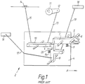
- a conventional automobile door locking system includes a key operated lock, and a latch device which is disposed at a free edge of the door.
- the latch device is linked to the lock through a link rod attached between the latch and a lever portion of the lock.
- the latch and lock are also connected by means of mechanical linkages to a cill button provided within the vehicle, located adjacent the internal edge of the window cill, which is raised to unlock the door, and lowered to lock the door.
- the linkages to the cill button and lock are usually connected at opposite ends of a lever device in the latch.
- Also connected to the latch through further linkages are an exterior handle release, and interior release.
- the lock itself conventionally comprises a central rotatable lock barrel having a keyway therein disposed within a housing, with an arrangement of tumblers adjacent the keyway which become appropriately aligned on insertion of the key to allow rotation of the barrel within the lock housing.
- a lever arrangement is driven by the barrel, with a mechanical linkage attached between the lever and the latch so that as the barrel is rotated in an unlocking or locking action the lever is raised or lowered, effecting locking or unlocking of the latch device. More specifically, the lock is arranged so that the key can only be inserted or retracted into the barrel when the barrel is at a particular orientation in the lock (a "neutral" position).
- Locking or unlocking requires the operator to rotate the key from this position so as to move the lever, and subsequently return the key to its neutral position to allow its retraction from the lock. To prevent the lever from following the key and barrel as they are rotated back to the neutral position in this action a degree of free play between the barrel and the lever is necessary. This is discussed in further detail in the specific description.
- the present invention seeks to provide a simple mechanical lock which can be readily incorporated into an otherwise conventional mechanical locking system, and which has a deadlock effect. When so incorporated even if access to the internal linkages within the door can be gained, the latch cannot be opened.
- a lock for attachment to a latch device comprising a housing, a generally cylindrical barrel arranged therein having a keyway, the barrel being rotatable within the housing on insertion of a key, and a lever, rotatable between a first position which represents a locked position and a second position angularly spaced from the first position which represents an unlocked position, characterised in that a cam is fixed to the barrel for rotation therewith; the lever is adapted to be rotated by the cam with free play provided between the lever and cam to allow the cam and barrel to be returned to a neutral position after locking and after unlocking without driving the lever therewith; and engagement means are provided between the lever and housing, said engagement means being adapted to prevent rotation of the lever when in the first position with the barrel in the neutral position.
- the engagement means comprise a locking element constrained to move with the lever on the rotation thereof, a first housing recess of the housing, at least a part of the locking element being received in said recess when the lever to the first position with the barrel in the neutral position, whereby rotation of the lever is prevented and the lock is deadlocked.
- the cam may comprise a generally circular plate an edge portion of which lies adjacent the locking element to prevent movement thereof from the first housing recess when the lock is deadlocked and having a first radial cam recess disposed so that it is angularly beyond the locking element in the direction of locking when the lock is deadlocked.
- a portion of the housing defining an edge of the first housing recess which lies in the unlocking direction may be shaped to urge said locking element radially inwardly as the lever is urged in the unlocking direction, whereby on rotation of the barrel in the unlocking direction the first cam recess becomes aligned with locking element which is received therein, allowing the lever to be rotated.
- the housing and cam are provided with second respective recesses angularly spaced from the first recesses in the unlocking direction, into which second housing recess said locking element is urged as the barrel is returned to the neutral position after movement of the lever to the unlocked position, and into which second cam recess the locking element is urged on rotation of the cam and lever in the locking direction from an unlocked position.
- the second housing recess permits limited rotation of the lever to a sufficient degree to allow conventional locking by means of a cill button without engaging the deadlock facility.
- the locking element is disposed at an outer edge of the lever, between a pair of upstanding lugs, one of which is abutted by a drive surface of the cam during rotation thereof on locking, and the other of which is abutted by an oppositely directed drive surface of the cam during rotation thereof during unlocking, said drive surfaces being angularly spaced to provide the free play between the cam and the lever.
- lugs thereby serve both to receive drive, and to constrain the locking element further simplifying the lock.
- the lever preferably comprises a plate-like member having a portion which overlies an end of the housing which is provided with an aperture therethrough through which a portion of the barrel extends, and an elongate portion extending radially therefrom, with said upstanding lugs provided at a side of the lever which is opposite to the elongate portion.
- the cam is preferably a plate-like member which overlies the lever, and is keyed to the barrel for rotation therewith.
- the lock can be formed of a very similar overall size to a conventional lock, so that a conventional lock can be readily replaced by a lock in accordance with the invention without modification of the vehicle door.
- the lock lever 12 in the locked condition which is illustrated in Figure 1, the lock lever 12 is free to pivot downwardly to a degree in a clockwise sense, owing to the freeplay which is provided between the lock barrel and the lever 12, which freeplay is provided to enable the key to be retracted from the barrel after locking, as discussed above.
- This freeplay means that a thief who obtains access to the rocker lever 10 or linkages 13 or 15 is able to move the rocker lever 10 to an unlocked position in which the door can be opened by operating the internal or external door releases 16,18. Also, if a thief breaks the vehicle window he can simply raise the cill button 14 to unlock the door.
- the lock in accordance with the present invention eliminates the need for this freeplay, and can be incorporated into the arrangement of Figure 1 to replace the conventional lock 11.
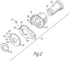
- a first embodiment of a lock in accordance with the present invention is illustrated in an exploded view in Figure 2, and in end views illustrating the locking and unlocking sequences, in Figures 3(a) to (f).
- the lever 26 comprises a generally circular portion which overlies the housing 21 and an elongate portion extending therefrom to which is attached a link rod 13 (not shown in Figure 2) which at its opposite end is coupled to the latch device 4, as shown in Figure 1.
- the lever 26 carries a cylindrical roller 40 which constitutes a locking element. This roller 40 is carried between opposed lugs 44,45 which upstand from a face of the lever 26. The roller 40 is however free to move radially between the lugs.
- the lever 26 is itself overlain by a rotary cam 30 in the form of a generally circular plate which is keyed to the lock barrel 22 for rotation therewith.
- An axially protruding lip-like edge region of the housing 21 defines a first housing recess 34 and second housing recess 32 separated by a housing land 36.
- the housing land 36 is defined between curved inclined surfaces which serve to force the roller 40 inwardly between the lugs 44 as the lever 26 carries the roller 40 thereover.
- the cam 30 includes an arcuate cut-out region 46 on a side thereof, which cut-out region comprises end stops 48,50 and curved first and second cam recesses 54,52 spaced from the respective end stops 50,48 with a cam land 53 therebetween.
- a cover portion upstanding from the cam 30 overlies the cut-out region to prevent exposure of this region of the lock 11'. This portion is, however, omitted from Figures 2, 3 and 4 for reasons of clarity.
- Element 56 is a retaining element in the form of a springy metal clip which serves to hold the cam 30 and lever 26 on the barrel 22.
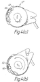
- Figure 3(a) shows the lock in its unlocked position, with the barrel 22 and cam 30 (which are fixed for rotation to each other) in a "neutral" position in which a key can be inserted or retracted.
- a key is inserted into the keyhole 24 and rotated in an anticlockwise sense as indicated in Figure 3(b).
- the end stop 48 of the cam 30 which faces the direction of rotation bears against the upstanding lug 44 so that the lever 26 is also driven in the anticlockwise direction.
- the lugs 44, 45 carry the roller 40 past the land 36, whose shape urges the roller radially inwards between the lugs 44,45 as it passes the housing land 36, and into the second cam recess 52.
- the roller 40 is carried beyond the housing land 36 to face the first housing recess 34 until the position of Figure 3(c) is reached.
- the cam 30 and barrel 22 are returned to the neutral position by a clockwise rotation to the position shown in Figure 3(d).
- the cam 30 and in particular the cam land 53 between the cam recesses 52 and 54 urges the roller 40 out into the first housing recess 34.
- the key is inserted into the keyhole 24 and rotated in a clockwise sense from the position of Figure 3(d), through the position of Figure 3(e) (which shows the end stop 50 of the cam 30 having just engaged the lug 45) to the position shown in Figure 3(f).
- the first cam recess 54 faces the roller 40.
- the roller 40 is urged into the first cam recess 54, past the housing land 36, and into the second housing recess 32, with the lever 26 now in the unlocked "down" position.
Landscapes
- Lock And Its Accessories (AREA)
- Mutual Connection Of Rods And Tubes (AREA)
- Quick-Acting Or Multi-Walled Pipe Joints (AREA)
Applications Claiming Priority (2)
| Application Number | Priority Date | Filing Date | Title |
|---|---|---|---|
| GB9401662A GB2286222B (en) | 1994-01-28 | 1994-01-28 | Mechanical deadlock |
| GB9401662 | 1994-01-28 |
Publications (3)
| Publication Number | Publication Date |
|---|---|
| EP0665352A1 true EP0665352A1 (de) | 1995-08-02 |
| EP0665352B1 EP0665352B1 (de) | 1998-04-29 |
| EP0665352B2 EP0665352B2 (de) | 2003-03-12 |
Family
ID=10749492
Family Applications (1)
| Application Number | Title | Priority Date | Filing Date |
|---|---|---|---|
| EP19950300391 Expired - Lifetime EP0665352B2 (de) | 1994-01-28 | 1995-01-23 | Verriegelbares, mechanisches Schloss |
Country Status (4)
| Country | Link |
|---|---|
| EP (1) | EP0665352B2 (de) |
| DE (1) | DE69502206T3 (de) |
| ES (1) | ES2116037T5 (de) |
| GB (1) | GB2286222B (de) |
Cited By (2)
| Publication number | Priority date | Publication date | Assignee | Title |
|---|---|---|---|---|
| US6609737B2 (en) | 2000-11-29 | 2003-08-26 | Meritor Light Vehicle Sytems ( Uk) Limited | Lock arrangement |
| EP3808925A1 (de) * | 2019-10-16 | 2021-04-21 | U-Shin France | Schloss für einen öffnungsflügel eines kraftfahrzeugs |
Citations (4)
| Publication number | Priority date | Publication date | Assignee | Title |
|---|---|---|---|---|
| DE2852310A1 (de) * | 1978-12-02 | 1980-06-12 | Daimler Benz Ag | Verriegelungsknopf |
| DE3623990A1 (de) * | 1985-07-26 | 1987-01-29 | Volkswagen Ag | Schliesssystem fuer eine fahrzeugtuer |
| DE3737700A1 (de) * | 1987-11-06 | 1989-05-18 | Bayerische Motoren Werke Ag | Hilfsbetaetigung fuer elektrisch verstellbare schliesseinrichtungen, insbesondere an kraftfahrzeugtueren |
| DE4312573A1 (de) * | 1992-04-30 | 1993-11-04 | Volkswagen Ag | Schliesssystem fuer eine kraftfahrzeugtuer |
Family Cites Families (5)
| Publication number | Priority date | Publication date | Assignee | Title |
|---|---|---|---|---|
| GB996052A (en) * | 1960-09-24 | 1965-06-23 | Wilmot Breeden Ltd | Improvements in or relating to locking mechanisms |
| DE2802408C2 (de) * | 1978-01-20 | 1985-12-05 | Hülsbeck & Fürst GmbH & Co KG, 5620 Velbert | Schließeinrichtung für Kraftfahrzeugtüren o.dgl. |
| DE2828563C3 (de) * | 1978-06-29 | 1981-11-12 | Hülsbeck & Fürst GmbH & Co KG, 5620 Velbert | Schließeinrichtung für einen Kraftfahrzeugtürverschluß |
| DE3513287A1 (de) * | 1985-04-13 | 1986-10-16 | Hülsbeck & Fürst GmbH & Co KG, 5620 Velbert | Schliesseinrichtung fuer den verschluss einer kraftfahrzeugtuer, vorzugsweise von personenkraftwagen |
| GB2228523B (en) * | 1989-02-23 | 1993-04-14 | Land Rover Uk Ltd | A locking mechanism |
-
1994
- 1994-01-28 GB GB9401662A patent/GB2286222B/en not_active Expired - Fee Related
-
1995
- 1995-01-23 DE DE1995602206 patent/DE69502206T3/de not_active Expired - Lifetime
- 1995-01-23 ES ES95300391T patent/ES2116037T5/es not_active Expired - Lifetime
- 1995-01-23 EP EP19950300391 patent/EP0665352B2/de not_active Expired - Lifetime
Patent Citations (4)
| Publication number | Priority date | Publication date | Assignee | Title |
|---|---|---|---|---|
| DE2852310A1 (de) * | 1978-12-02 | 1980-06-12 | Daimler Benz Ag | Verriegelungsknopf |
| DE3623990A1 (de) * | 1985-07-26 | 1987-01-29 | Volkswagen Ag | Schliesssystem fuer eine fahrzeugtuer |
| DE3737700A1 (de) * | 1987-11-06 | 1989-05-18 | Bayerische Motoren Werke Ag | Hilfsbetaetigung fuer elektrisch verstellbare schliesseinrichtungen, insbesondere an kraftfahrzeugtueren |
| DE4312573A1 (de) * | 1992-04-30 | 1993-11-04 | Volkswagen Ag | Schliesssystem fuer eine kraftfahrzeugtuer |
Cited By (3)
| Publication number | Priority date | Publication date | Assignee | Title |
|---|---|---|---|---|
| US6609737B2 (en) | 2000-11-29 | 2003-08-26 | Meritor Light Vehicle Sytems ( Uk) Limited | Lock arrangement |
| EP3808925A1 (de) * | 2019-10-16 | 2021-04-21 | U-Shin France | Schloss für einen öffnungsflügel eines kraftfahrzeugs |
| FR3102202A1 (fr) * | 2019-10-16 | 2021-04-23 | U-Shin France | Serrure pour un ouvrant de véhicule automobile |
Also Published As
| Publication number | Publication date |
|---|---|
| GB2286222A (en) | 1995-08-09 |
| DE69502206T3 (de) | 2003-11-13 |
| DE69502206D1 (de) | 1998-06-04 |
| GB2286222B (en) | 1997-05-28 |
| EP0665352B2 (de) | 2003-03-12 |
| ES2116037T5 (es) | 2003-12-01 |
| DE69502206T2 (de) | 1998-08-27 |
| ES2116037T3 (es) | 1998-07-01 |
| GB9401662D0 (en) | 1994-03-23 |
| EP0665352B1 (de) | 1998-04-29 |
Similar Documents
| Publication | Publication Date | Title |
|---|---|---|
| CN1550629B (zh) | 锁机构 | |
| EP1136641B1 (de) | Verriegelungsvorrichtung | |
| US5715713A (en) | Door latch locking actuator assembly | |
| US4951486A (en) | Nested paddle lock assembly | |
| US6327881B1 (en) | Locking device | |
| US6139073A (en) | Lock assembly | |
| US8562033B2 (en) | Double lock override mechanism for vehicular passive entry door latch | |
| US6526790B2 (en) | Closing device | |
| US5419597A (en) | Power-actuated motor-vehicle door latch with antitheft override | |
| US5066054A (en) | Motor-vehicle door latch with antitheft feature | |
| US5899508A (en) | Double locking vehicle door latch | |
| JPS63261076A (ja) | ドアーロック | |
| US20040012468A1 (en) | Electrically operated ratcheting pawl latch | |
| US20060049642A1 (en) | Lock for an opening on a motor vehicle, with a memory for unlocking locking | |
| GB2337295A (en) | Anti-panic vehicle door latch device | |
| US6082158A (en) | Closing device | |
| US5878605A (en) | Lock, in particular mortise lock | |
| EP0769599B1 (de) | Kraftfahrzeugstürschloss | |
| GB2342383A (en) | Vehicle door latch with a lock link which engages a pawl lifter and release lever during door unlocking | |
| US7424814B2 (en) | Dead bolt lock system having multiple security features | |
| GB2271380A (en) | Lock mechanism with deadlocking latchbolt | |
| EP0665352B1 (de) | Verriegelbares, mechanisches Schloss | |
| EP0026174B1 (de) | Fahrzeug-türschloss | |
| US3543546A (en) | Automobile door safety lock | |
| GB2306559A (en) | Locks |
Legal Events
| Date | Code | Title | Description |
|---|---|---|---|
| PUAI | Public reference made under article 153(3) epc to a published international application that has entered the european phase |
Free format text: ORIGINAL CODE: 0009012 |
|
| AK | Designated contracting states |
Kind code of ref document: A1 Designated state(s): DE ES FR IT |
|
| 17P | Request for examination filed |
Effective date: 19951122 |
|
| GRAG | Despatch of communication of intention to grant |
Free format text: ORIGINAL CODE: EPIDOS AGRA |
|
| 17Q | First examination report despatched |
Effective date: 19970718 |
|
| GRAG | Despatch of communication of intention to grant |
Free format text: ORIGINAL CODE: EPIDOS AGRA |
|
| GRAH | Despatch of communication of intention to grant a patent |
Free format text: ORIGINAL CODE: EPIDOS IGRA |
|
| GRAH | Despatch of communication of intention to grant a patent |
Free format text: ORIGINAL CODE: EPIDOS IGRA |
|
| GRAA | (expected) grant |
Free format text: ORIGINAL CODE: 0009210 |
|
| AK | Designated contracting states |
Kind code of ref document: B1 Designated state(s): DE ES FR IT |
|
| REF | Corresponds to: |
Ref document number: 69502206 Country of ref document: DE Date of ref document: 19980604 |
|
| REG | Reference to a national code |
Ref country code: ES Ref legal event code: FG2A Ref document number: 2116037 Country of ref document: ES Kind code of ref document: T3 |
|
| ITF | It: translation for a ep patent filed | ||
| ET | Fr: translation filed | ||
| PLBQ | Unpublished change to opponent data |
Free format text: ORIGINAL CODE: EPIDOS OPPO |
|
| PLBI | Opposition filed |
Free format text: ORIGINAL CODE: 0009260 |
|
| PLBF | Reply of patent proprietor to notice(s) of opposition |
Free format text: ORIGINAL CODE: EPIDOS OBSO |
|
| 26 | Opposition filed |
Opponent name: HUF HUELSBECK & FUERST GMBH. & CO. KG. Effective date: 19990123 |
|
| PLBF | Reply of patent proprietor to notice(s) of opposition |
Free format text: ORIGINAL CODE: EPIDOS OBSO |
|
| PLAW | Interlocutory decision in opposition |
Free format text: ORIGINAL CODE: EPIDOS IDOP |
|
| PLAW | Interlocutory decision in opposition |
Free format text: ORIGINAL CODE: EPIDOS IDOP |
|
| PUAH | Patent maintained in amended form |
Free format text: ORIGINAL CODE: 0009272 |
|
| STAA | Information on the status of an ep patent application or granted ep patent |
Free format text: STATUS: PATENT MAINTAINED AS AMENDED |
|
| 27A | Patent maintained in amended form |
Effective date: 20030312 |
|
| AK | Designated contracting states |
Designated state(s): DE ES FR IT |
|
| ET3 | Fr: translation filed ** decision concerning opposition | ||
| PGFP | Annual fee paid to national office [announced via postgrant information from national office to epo] |
Ref country code: FR Payment date: 20120209 Year of fee payment: 18 |
|
| PGFP | Annual fee paid to national office [announced via postgrant information from national office to epo] |
Ref country code: DE Payment date: 20120118 Year of fee payment: 18 |
|
| PGFP | Annual fee paid to national office [announced via postgrant information from national office to epo] |
Ref country code: IT Payment date: 20120127 Year of fee payment: 18 |
|
| PGFP | Annual fee paid to national office [announced via postgrant information from national office to epo] |
Ref country code: ES Payment date: 20120126 Year of fee payment: 18 |
|
| REG | Reference to a national code |
Ref country code: FR Ref legal event code: ST Effective date: 20130930 |
|
| PG25 | Lapsed in a contracting state [announced via postgrant information from national office to epo] |
Ref country code: DE Free format text: LAPSE BECAUSE OF NON-PAYMENT OF DUE FEES Effective date: 20130801 |
|
| REG | Reference to a national code |
Ref country code: DE Ref legal event code: R119 Ref document number: 69502206 Country of ref document: DE Effective date: 20130801 |
|
| PG25 | Lapsed in a contracting state [announced via postgrant information from national office to epo] |
Ref country code: FR Free format text: LAPSE BECAUSE OF NON-PAYMENT OF DUE FEES Effective date: 20130131 |
|
| PG25 | Lapsed in a contracting state [announced via postgrant information from national office to epo] |
Ref country code: IT Free format text: LAPSE BECAUSE OF NON-PAYMENT OF DUE FEES Effective date: 20130123 |
|
| REG | Reference to a national code |
Ref country code: ES Ref legal event code: FD2A Effective date: 20140321 |
|
| PG25 | Lapsed in a contracting state [announced via postgrant information from national office to epo] |
Ref country code: ES Free format text: LAPSE BECAUSE OF NON-PAYMENT OF DUE FEES Effective date: 20130124 |