EP0665404B1 - Tube cylindrique flexible pour le transport de gaz - Google Patents
Tube cylindrique flexible pour le transport de gaz Download PDFInfo
- Publication number
- EP0665404B1 EP0665404B1 EP95400167A EP95400167A EP0665404B1 EP 0665404 B1 EP0665404 B1 EP 0665404B1 EP 95400167 A EP95400167 A EP 95400167A EP 95400167 A EP95400167 A EP 95400167A EP 0665404 B1 EP0665404 B1 EP 0665404B1
- Authority
- EP
- European Patent Office
- Prior art keywords
- tube
- tape
- covering
- support
- flexible
- Prior art date
- Legal status (The legal status is an assumption and is not a legal conclusion. Google has not performed a legal analysis and makes no representation as to the accuracy of the status listed.)
- Expired - Lifetime
Links
- 230000009975 flexible effect Effects 0.000 claims description 23
- 239000000463 material Substances 0.000 claims description 14
- 239000007789 gas Substances 0.000 claims description 7
- 239000011358 absorbing material Substances 0.000 claims description 4
- 239000004744 fabric Substances 0.000 claims description 4
- 229910052751 metal Inorganic materials 0.000 claims description 4
- 239000002184 metal Substances 0.000 claims description 4
- 238000004804 winding Methods 0.000 claims 1
- 238000000576 coating method Methods 0.000 description 13
- 239000011248 coating agent Substances 0.000 description 11
- 239000007779 soft material Substances 0.000 description 5
- 238000004519 manufacturing process Methods 0.000 description 4
- 230000002745 absorbent Effects 0.000 description 2
- 239000002250 absorbent Substances 0.000 description 2
- 229910052782 aluminium Inorganic materials 0.000 description 2
- XAGFODPZIPBFFR-UHFFFAOYSA-N aluminium Chemical compound [Al] XAGFODPZIPBFFR-UHFFFAOYSA-N 0.000 description 2
- 238000007789 sealing Methods 0.000 description 2
- 229920000914 Metallic fiber Polymers 0.000 description 1
- 229910000831 Steel Inorganic materials 0.000 description 1
- 210000001015 abdomen Anatomy 0.000 description 1
- 238000004026 adhesive bonding Methods 0.000 description 1
- 239000010426 asphalt Substances 0.000 description 1
- 238000005253 cladding Methods 0.000 description 1
- 238000002485 combustion reaction Methods 0.000 description 1
- 239000002131 composite material Substances 0.000 description 1
- 238000010276 construction Methods 0.000 description 1
- 238000005516 engineering process Methods 0.000 description 1
- 238000004880 explosion Methods 0.000 description 1
- 239000011152 fibreglass Substances 0.000 description 1
- 238000000034 method Methods 0.000 description 1
- 239000004033 plastic Substances 0.000 description 1
- 239000010959 steel Substances 0.000 description 1
- 238000011282 treatment Methods 0.000 description 1
Images
Classifications
-
- F—MECHANICAL ENGINEERING; LIGHTING; HEATING; WEAPONS; BLASTING
- F16—ENGINEERING ELEMENTS AND UNITS; GENERAL MEASURES FOR PRODUCING AND MAINTAINING EFFECTIVE FUNCTIONING OF MACHINES OR INSTALLATIONS; THERMAL INSULATION IN GENERAL
- F16L—PIPES; JOINTS OR FITTINGS FOR PIPES; SUPPORTS FOR PIPES, CABLES OR PROTECTIVE TUBING; MEANS FOR THERMAL INSULATION IN GENERAL
- F16L9/00—Rigid pipes
- F16L9/21—Rigid pipes made of sound-absorbing materials or with sound-absorbing structure
-
- F—MECHANICAL ENGINEERING; LIGHTING; HEATING; WEAPONS; BLASTING
- F02—COMBUSTION ENGINES; HOT-GAS OR COMBUSTION-PRODUCT ENGINE PLANTS
- F02M—SUPPLYING COMBUSTION ENGINES IN GENERAL WITH COMBUSTIBLE MIXTURES OR CONSTITUENTS THEREOF
- F02M35/00—Combustion-air cleaners, air intakes, intake silencers, or induction systems specially adapted for, or arranged on, internal-combustion engines
- F02M35/12—Intake silencers ; Sound modulation, transmission or amplification
- F02M35/1205—Flow throttling or guiding
- F02M35/1216—Flow throttling or guiding by using a plurality of holes, slits, protrusions, perforations, ribs or the like; Surface structures; Turbulence generators
-
- F—MECHANICAL ENGINEERING; LIGHTING; HEATING; WEAPONS; BLASTING
- F02—COMBUSTION ENGINES; HOT-GAS OR COMBUSTION-PRODUCT ENGINE PLANTS
- F02M—SUPPLYING COMBUSTION ENGINES IN GENERAL WITH COMBUSTIBLE MIXTURES OR CONSTITUENTS THEREOF
- F02M35/00—Combustion-air cleaners, air intakes, intake silencers, or induction systems specially adapted for, or arranged on, internal-combustion engines
- F02M35/12—Intake silencers ; Sound modulation, transmission or amplification
- F02M35/1272—Intake silencers ; Sound modulation, transmission or amplification using absorbing, damping, insulating or reflecting materials, e.g. porous foams, fibres, rubbers, fabrics, coatings or membranes
Definitions
- the invention relates to cylindrical tubes hoses for the transport of air or other gases, used especially in the automotive industry where their goal is, between others, to bring the air to the internal combustion engines, avoiding excessive propagation of original noise mechanical, an aspect that adds to the heat resistance and vibration, longer service life and low production cost.
- a tube flexible cylindrical intended for the transport of air or others gas, used in particular in the automotive industry, where its purpose is, among other things, to bring air to the engines at explosion, and comprising at least one cylindrical coating flexible, made of a material considered soft and absorbing noise, and a support tape provided with openings, against which said coating is placed.
- the support tape openwork for example metal (steel, aluminum, etc.), gives radial consistency and flexibility, avoiding excessive propagation of noise by the development of acoustic characteristics. This is due to the openings of the stringer tape.
- the covering can be a fabric of any kind, felt, paper or other absorbent material noises, all these materials being considered as soft materials. It can also be composite, i.e. have at least two layers. Such a coating can be provided inside and / or outside of the support tape.
- the mechanical noises that this emits are transformed into pulses or waves at inside the tube.
- the waves pass through the openings of the support tape and they are amortized, before and / or after, by the material of the coating or coatings which absorb the noises.
- a gas transport tube in pulsed regime has a resonant frequency which depends in particular on its length. At this resonant frequency, the amplitude of waves is maximum and therefore the tube is very noisy.
- the invention relates to an even more flexible tube as silent as those of the prior art. This is achieved by the features of claim 1.
- the subclaims aimed at advantageous improvements.
- the presence of the soft coating (s) allows, possibly with partial passage of gas through the or the coatings, according to the pressure differential between the tube and outside and according to the envisaged applications, to reduce the pressure bellies which generate the noise.
- the support tape is for example constituted by a perforated tape, mesh tape, braid or mesh.
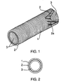
- the tube according to the invention comprises a support tape 2, helical and corrugated, made of metal or any other material easy to shape, provided with 2A openings ensuring the passage of sound waves, and at least one coating 1.3 of a material soft absorbing vibrations, and therefore noise.
- This soft material is for example a fabric of any suitable type, paper or felt, if applicable coated with an outer layer, for example in bonded bitumen.
- openings their nature depends on the support tape structure 2. They are functionally defined as physical passages through the wall support tape allowing free radial crossing of this last by the sound waves carried in the tube. Through example, in the case of a perforated metal strip, these openings are perforations. In addition, these openings form axial discontinuities in the material of the support tape, these discontinuities opposing the axial propagation of sounds in the material itself of the backing tape.
- the flexible cylindrical tube shown in Figs. 1 and 2 is formed by a central support tape 2, on which are placed by superposition, helical or not, and by bonding or not, two flexible coverings, one exterior 1 larger in diameter than the support tape and the other interior 3 of smaller diameter, made in any what appropriate type of fabric or absorbent material noises, considered as a soft material, in accordance with this which was previously described.
- the sound waves which have penetrated in the flexible cylindrical tube, are initially damped and filtered by the soft material of the inner lining 3 which absorbs noise. They then pass through holes 2A backing tape 2 and they are finally absorbed by the soft material of the outer covering 1 which absorbs noises.
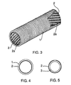
- the tube may include the defined support tape 2 previously and, by superposition, helical or not, and by gluing or not, only the outer coating 1 above.
- the sound waves are initially absorbed by the openings 2A of the support tape 2 and then be absorbed by the soft sound absorbing material of the exterior cladding 1.
- the tube may include the support tape 2 defined previously and, by helical overlay or not, and by bonding or not, only the inner coating 3.
- the tube flexible cylindrical will therefore consist of a support tape 2 exterior, with its openings 2A, and an interior coating 3, of a smaller diameter, cylindrical and flexible.
- the sound waves are initially damped and filtered by the soft sound absorbing material of the interior lining 3. Then what remains of the waves passes by the openings 2A of the support tape 2.
- the invention therefore provides a cylindrical tube flexible which prevents excessive propagation of noise mechanical origin due to acoustic conditions improved, collaborating in this way to decrease sensitive to sound cues, especially in large urban or industrial centers.
Landscapes
- Engineering & Computer Science (AREA)
- General Engineering & Computer Science (AREA)
- Mechanical Engineering (AREA)
- Chemical & Material Sciences (AREA)
- Combustion & Propulsion (AREA)
- Rigid Pipes And Flexible Pipes (AREA)
- Laminated Bodies (AREA)
- Pipe Accessories (AREA)
- Exhaust Silencers (AREA)
Description
Claims (11)
- Tube cylindrique flexible destiné au transport de l'air ou d'autres gaz, utilisé notamment dans l'industrie automobile, et consistant en au moins un revêtement (1, 3) cylindrique flexible, en un matériau considéré comme mou et absorbant les bruits ; et un ruban-support (2) pourvu d'ajours (2A), contre lequel le revêtement (1, 3) est placé, caractérisé en ce que tous les revêtements (1, 3) sont en un matériau perméable aux gaz de manière à permettre le passage du gaz entre le tube et l'extérieur.
- Tube selon la revendication 1, caractérisé en ce qu'il existe un seul revêtement (1), constituant un revêtement extérieur de diamètre supérieur à celui du ruban-support (2).
- Tube selon la revendication 1, caractérisé en ce qu'il existe un seul revêtement (3) constituant un revêtement intérieur de diamètre inférieur à celui du ruban-support (2).
- Tube selon la revendication 1, caractérisé en ce qu'il existe un revêtement extérieur (1) de diamètre supérieur à celui du ruban-support, et un revêtement intérieur (3) de diamètre inférieur à celui du ruban-support (2).
- Tube selon l'une des revendications 1 à 4, caractérisé en ce que le ruban-support (2) et/ou le revêtement (1, 3) sont obtenus par enroulement hélicoïdal.
- Tube selon l'une des revendications 1 à 5, caractérisé en ce que le ruban-support (2) et le revêtement (1, 3) sont collés entre eux.
- Tube selon l'une des revendications 1 à 6, caractérisé en ce que le revêtement (1, 3) est en un matériau appartenant au groupe constitué par du tissu, du feutre et du papier.
- Tube selon l'une des revendications 1 à 7, caractérisé en ce que le ruban-support (2) et/ou le revêtement (1, 3) sont ondulés.
- Tube selon l'une des revendications 1 à 8, caractérisé en ce que le ruban-support (2) est en un matériau facile à travailler.
- Tube selon la revendication 9, caractérisé en ce que le ruban-support (2) est en métal.
- Tube selon l'une des revendications 1 à 10, caractérisé en ce que le ruban-support (2) appartient au groupe constitué par une bande perforée, une bande grillagée, une tresse et un treillis.
Applications Claiming Priority (2)
| Application Number | Priority Date | Filing Date | Title |
|---|---|---|---|
| BR7400072U BR7400072U (pt) | 1994-01-28 | 1994-01-28 | Disposições construtivas introduzidas em bubo cilíndrico flexível |
| BR7400072U | 1994-01-28 |
Publications (2)
| Publication Number | Publication Date |
|---|---|
| EP0665404A1 EP0665404A1 (fr) | 1995-08-02 |
| EP0665404B1 true EP0665404B1 (fr) | 2003-11-05 |
Family
ID=3989767
Family Applications (1)
| Application Number | Title | Priority Date | Filing Date |
|---|---|---|---|
| EP95400167A Expired - Lifetime EP0665404B1 (fr) | 1994-01-28 | 1995-01-26 | Tube cylindrique flexible pour le transport de gaz |
Country Status (6)
| Country | Link |
|---|---|
| US (1) | US5603358A (fr) |
| EP (1) | EP0665404B1 (fr) |
| BR (1) | BR7400072U (fr) |
| DE (1) | DE69532054T2 (fr) |
| ES (1) | ES2208667T3 (fr) |
| PT (1) | PT665404E (fr) |
Families Citing this family (23)
| Publication number | Priority date | Publication date | Assignee | Title |
|---|---|---|---|---|
| DE19547031A1 (de) * | 1995-12-15 | 1997-06-19 | Eilentropp Kg | Langgestreckte rohrförmige Hülle |
| US5927344A (en) * | 1996-01-03 | 1999-07-27 | Nobileau; Philippe | Subsea flexible pipe |
| DE19635799B4 (de) * | 1996-09-04 | 2008-11-20 | Adam Opel Ag | Dämpfungsschlauch |
| DE19711586C2 (de) * | 1997-03-19 | 1999-11-04 | Geberit Technik Ag | Kunststoff-Rohrteil, insbesondere Bogen- und Abzweig-Formstück, für Rohrsysteme in Abwasser-Hausinstallationen sowie dessen Verwendung in einem solchen Rohrleitungssystem |
| FR2762892B1 (fr) * | 1997-04-30 | 1999-07-02 | Westaflex Automobile | Tuyau pour le transport de fluides gazeux, notamment dans les automobiles |
| BR9900914A (pt) * | 1999-04-20 | 2000-10-24 | Edmond Pol Jean Lepoutre | Dispositivo controlador de porosidade em tubo helicoidal flexìvel acústico condutor de ar |
| DE19932198C2 (de) * | 1999-07-09 | 2001-10-25 | Alcan Gmbh | Flexibles Rohr oder flexibler Schlauch |
| DE19942369A1 (de) * | 1999-09-04 | 2001-03-08 | Cww Gerko Akustik Gmbh & Co Kg | Kunststoffrohr, insbesondere Kunststoff-Fallrohr |
| GB0025301D0 (en) * | 2000-10-14 | 2000-11-29 | Boreas Consultants Ltd | Lined pipeline vent |
| WO2003042604A1 (fr) * | 2001-11-13 | 2003-05-22 | Bhp Billiton Innovation Pty Ltd | Distributeur d'air pour un systeme de biolixivation |
| US6941972B2 (en) * | 2002-07-25 | 2005-09-13 | Hancor, Inc. | Corrugated pipe |
| DE10317224B4 (de) * | 2003-04-15 | 2011-11-17 | Bayerische Motoren Werke Aktiengesellschaft | Vorrichtung zur Reduzierung von Schallemissionen |
| US7690549B1 (en) * | 2003-06-18 | 2010-04-06 | Owensby Howard S | Purge line for welding backup |
| US7410550B2 (en) * | 2003-12-11 | 2008-08-12 | Sherwin Michael J | Flexible insulating sleeve |
| US7111601B2 (en) * | 2004-03-18 | 2006-09-26 | Visteon Global Technologies, Inc. | Air induction system having an environmentally resistant acoustic membrane |
| DE102004028744B3 (de) * | 2004-06-14 | 2005-10-27 | Veritas Ag | Schalldämpfer |
| EP2270378A1 (fr) * | 2009-07-02 | 2011-01-05 | LANXESS Deutschland GmbH | Tuyau flexible |
| DE202011104564U1 (de) * | 2011-08-18 | 2012-11-19 | Witzenmann Gmbh | Flexibles Leitungselement mit Dämpfung |
| CN104266029B (zh) * | 2014-09-26 | 2017-01-18 | 安徽正石新型建材有限公司 | 一种低噪排水管 |
| US10554027B2 (en) | 2016-02-03 | 2020-02-04 | Electrolock, Inc. | Protective cover for cable components |
| US9716375B1 (en) | 2016-02-03 | 2017-07-25 | Electrolock, Inc. | Method of fabricating a protective cover from foil-backed fiberglass substrate |
| FR3067280B1 (fr) | 2017-06-09 | 2019-07-19 | Novares France | Procede de fabrication d’un conduit d’admission d’air |
| AU2024213185A1 (en) * | 2024-08-22 | 2026-03-12 | Jmax Engineering Pty Ltd | Noise Attenuating Snorkel Body |
Family Cites Families (13)
| Publication number | Priority date | Publication date | Assignee | Title |
|---|---|---|---|---|
| US1190292A (en) * | 1915-08-27 | 1916-07-11 | Mechanical Rubber Co | Process of making hose. |
| US2089492A (en) * | 1935-07-06 | 1937-08-10 | American Radiator Co | Duct |
| US2906638A (en) * | 1954-07-09 | 1959-09-29 | Us Rubber Co | Method of coating seamless braided glass fiber tubes |
| CH538748A (fr) * | 1971-10-07 | 1973-06-30 | Urech Ernest | Isolation pour l'insonorisation de conduite d'écoulement |
| GB1441742A (en) * | 1972-08-15 | 1976-07-07 | Smiths Industries Ltd | Tubing |
| US4013102A (en) * | 1975-01-30 | 1977-03-22 | John Z. Delorean Corporation | Composite tubing |
| US4153080A (en) * | 1978-04-13 | 1979-05-08 | Goodall Rubber Company | Fire hose and method of making it |
| US4547193A (en) * | 1984-04-05 | 1985-10-15 | Angiomedics Incorporated | Catheter having embedded multi-apertured film |
| US4926909A (en) * | 1986-07-14 | 1990-05-22 | The Gates Rubber Company | Intersticed nipple for elastomeric hose |
| GB8727694D0 (en) * | 1987-11-26 | 1987-12-31 | Jaguar Cars | Insulated pipe |
| SE461417B (sv) * | 1988-06-15 | 1990-02-12 | Dorchester Enterprises Ltd | Ljuddaempande avgasledning |
| DE9015414U1 (de) * | 1990-11-09 | 1991-01-24 | Alcan Deutschland GmbH, 3400 Göttingen | Schalldämmendes Luft- oder Gasführungselement |
| US5325893A (en) * | 1991-10-04 | 1994-07-05 | Tokushu Paper Mfg. Co., Ltd. | Air duct and paper therefor |
-
1994
- 1994-01-28 BR BR7400072U patent/BR7400072U/pt not_active IP Right Cessation
-
1995
- 1995-01-26 PT PT95400167T patent/PT665404E/pt unknown
- 1995-01-26 DE DE69532054T patent/DE69532054T2/de not_active Expired - Fee Related
- 1995-01-26 ES ES95400167T patent/ES2208667T3/es not_active Expired - Lifetime
- 1995-01-26 EP EP95400167A patent/EP0665404B1/fr not_active Expired - Lifetime
- 1995-01-27 US US08/379,253 patent/US5603358A/en not_active Expired - Lifetime
Also Published As
| Publication number | Publication date |
|---|---|
| PT665404E (pt) | 2004-03-31 |
| EP0665404A1 (fr) | 1995-08-02 |
| ES2208667T3 (es) | 2004-06-16 |
| DE69532054D1 (de) | 2003-12-11 |
| BR7400072U (pt) | 1994-10-04 |
| US5603358A (en) | 1997-02-18 |
| DE69532054T2 (de) | 2004-08-26 |
Similar Documents
| Publication | Publication Date | Title |
|---|---|---|
| EP0665404A1 (fr) | Tube cylindrique flexible pour le transport de gaz | |
| CA2373188C (fr) | Procede de fabrication d'un panneau a couche resistive acoustique adaptee et panneau acoustique ainsi obtenu | |
| EP1398473B1 (fr) | Couche acoustiquement resistive pour panneau d'atténuation acoustique, panneau utilisant une telle couche | |
| EP0940248B1 (fr) | Panneau insonorisant et procédé de réalisation | |
| EP3489487B1 (fr) | Panneau d'atténuation acoustique pour aéronef | |
| EP0890056B1 (fr) | Tuyau pour canalisations du type a double enveloppe d'isolation thermique | |
| CA2700183A1 (fr) | Structure a ame alveolaire pour panneau acoustique | |
| FR2725259A1 (fr) | Bague d'etancheite activee par pression | |
| EP0855496B1 (fr) | Flexible de découplage monté dans une ligne d'échappement d'un moteur de véhicule automobile | |
| CA2292821C (fr) | Dispositif d'echappement multicanal de turbomachine traite acoustiquement | |
| EP1157372B1 (fr) | Procede de fabrication d'un panneau d'attenuation acoustique a couche resistive a propriete structurale et panneau ainsi obtenu | |
| CA2685287A1 (fr) | Panneau acoustique a caracteristique acoustique variable | |
| FR2975943A1 (fr) | Procede de fabrication d'un panneau d'attenuation acoustique | |
| EP3718759B1 (fr) | Assemblage constituant un materiau acoustiquement absorbant | |
| US20030098200A1 (en) | Acoustical absorptive splitter | |
| JP3521404B2 (ja) | 可撓性のコード状中空物及びこの中空物を通過する流体の透過防止方法 | |
| FR2537048A1 (fr) | Lame de matiere plastique renforcee de fibres et son procede de fabrication | |
| FR2856456A1 (fr) | Dispositif d'etancheite pour l'obturation temporaire d'un puits ou d'une canalisation. | |
| JPH09170554A (ja) | コンプレッサ用パルスダンパ即ち音響アウトレットピース及びこれを備えたコンプレッサ | |
| EP1091155B1 (fr) | Dispositif de contrôle de la porosité d'un tuyau acoustique flexible conducteur d'air | |
| EP3683056A1 (fr) | Procédé de fabrication d'une structure acoustiquement résistive, structure acoustiquement résistive ainsi obtenue, panneau d'absorption acoustique comportant ladite structure acoustiquement résistive | |
| FR2928415A1 (fr) | Panneau acoustique d'une nacelle d'un aeronef | |
| FR2927952A1 (fr) | Paroi insonorisante, en particulier pour nacelle de turboreacteur | |
| FR2505057A1 (fr) | Element porteur non metallique pour cable et cable comportant un tel porteur | |
| CN1035894C (zh) | 废气的催化清洁装置 |
Legal Events
| Date | Code | Title | Description |
|---|---|---|---|
| PUAI | Public reference made under article 153(3) epc to a published international application that has entered the european phase |
Free format text: ORIGINAL CODE: 0009012 |
|
| AK | Designated contracting states |
Kind code of ref document: A1 Designated state(s): DE ES FR GB IT PT SE |
|
| 17P | Request for examination filed |
Effective date: 19960116 |
|
| 17Q | First examination report despatched |
Effective date: 19980827 |
|
| 19U | Interruption of proceedings before grant |
Effective date: 19980611 |
|
| 19W | Proceedings resumed before grant after interruption of proceedings |
Effective date: 19981119 |
|
| GRAH | Despatch of communication of intention to grant a patent |
Free format text: ORIGINAL CODE: EPIDOS IGRA |
|
| GRAS | Grant fee paid |
Free format text: ORIGINAL CODE: EPIDOSNIGR3 |
|
| GRAA | (expected) grant |
Free format text: ORIGINAL CODE: 0009210 |
|
| RAP1 | Party data changed (applicant data changed or rights of an application transferred) |
Owner name: WECOSTA |
|
| AK | Designated contracting states |
Kind code of ref document: B1 Designated state(s): DE ES FR GB IT PT SE |
|
| REG | Reference to a national code |
Ref country code: GB Ref legal event code: FG4D Free format text: NOT ENGLISH |
|
| REF | Corresponds to: |
Ref document number: 69532054 Country of ref document: DE Date of ref document: 20031211 Kind code of ref document: P |
|
| REG | Reference to a national code |
Ref country code: SE Ref legal event code: TRGR |
|
| GBT | Gb: translation of ep patent filed (gb section 77(6)(a)/1977) |
Effective date: 20040218 |
|
| REG | Reference to a national code |
Ref country code: PT Ref legal event code: SC4A Free format text: AVAILABILITY OF NATIONAL TRANSLATION Effective date: 20040114 |
|
| REG | Reference to a national code |
Ref country code: ES Ref legal event code: FG2A Ref document number: 2208667 Country of ref document: ES Kind code of ref document: T3 |
|
| PLBE | No opposition filed within time limit |
Free format text: ORIGINAL CODE: 0009261 |
|
| STAA | Information on the status of an ep patent application or granted ep patent |
Free format text: STATUS: NO OPPOSITION FILED WITHIN TIME LIMIT |
|
| 26N | No opposition filed |
Effective date: 20040806 |
|
| PG25 | Lapsed in a contracting state [announced via postgrant information from national office to epo] |
Ref country code: IT Free format text: LAPSE BECAUSE OF NON-PAYMENT OF DUE FEES;WARNING: LAPSES OF ITALIAN PATENTS WITH EFFECTIVE DATE BEFORE 2007 MAY HAVE OCCURRED AT ANY TIME BEFORE 2007. THE CORRECT EFFECTIVE DATE MAY BE DIFFERENT FROM THE ONE RECORDED. Effective date: 20050126 |
|
| PGFP | Annual fee paid to national office [announced via postgrant information from national office to epo] |
Ref country code: SE Payment date: 20071219 Year of fee payment: 14 |
|
| PGFP | Annual fee paid to national office [announced via postgrant information from national office to epo] |
Ref country code: GB Payment date: 20071207 Year of fee payment: 14 Ref country code: ES Payment date: 20080125 Year of fee payment: 14 |
|
| PGFP | Annual fee paid to national office [announced via postgrant information from national office to epo] |
Ref country code: PT Payment date: 20071217 Year of fee payment: 14 Ref country code: DE Payment date: 20080107 Year of fee payment: 14 |
|
| PGFP | Annual fee paid to national office [announced via postgrant information from national office to epo] |
Ref country code: FR Payment date: 20071220 Year of fee payment: 14 |
|
| REG | Reference to a national code |
Ref country code: PT Ref legal event code: MM4A Free format text: LAPSE DUE TO NON-PAYMENT OF FEES Effective date: 20090727 |
|
| EUG | Se: european patent has lapsed | ||
| GBPC | Gb: european patent ceased through non-payment of renewal fee |
Effective date: 20090126 |
|
| PG25 | Lapsed in a contracting state [announced via postgrant information from national office to epo] |
Ref country code: PT Free format text: LAPSE BECAUSE OF NON-PAYMENT OF DUE FEES Effective date: 20090727 Ref country code: DE Free format text: LAPSE BECAUSE OF NON-PAYMENT OF DUE FEES Effective date: 20090801 |
|
| REG | Reference to a national code |
Ref country code: FR Ref legal event code: ST Effective date: 20091030 |
|
| PG25 | Lapsed in a contracting state [announced via postgrant information from national office to epo] |
Ref country code: GB Free format text: LAPSE BECAUSE OF NON-PAYMENT OF DUE FEES Effective date: 20090126 |
|
| REG | Reference to a national code |
Ref country code: ES Ref legal event code: FD2A Effective date: 20090127 |
|
| PG25 | Lapsed in a contracting state [announced via postgrant information from national office to epo] |
Ref country code: FR Free format text: LAPSE BECAUSE OF NON-PAYMENT OF DUE FEES Effective date: 20090202 Ref country code: ES Free format text: LAPSE BECAUSE OF NON-PAYMENT OF DUE FEES Effective date: 20090127 |
|
| PGFP | Annual fee paid to national office [announced via postgrant information from national office to epo] |
Ref country code: IT Payment date: 20080123 Year of fee payment: 14 |
|
| PGRI | Patent reinstated in contracting state [announced from national office to epo] |
Ref country code: IT Effective date: 20091201 |
|
| PGRI | Patent reinstated in contracting state [announced from national office to epo] |
Ref country code: IT Effective date: 20091201 |
|
| PG25 | Lapsed in a contracting state [announced via postgrant information from national office to epo] |
Ref country code: SE Free format text: LAPSE BECAUSE OF NON-PAYMENT OF DUE FEES Effective date: 20090127 |