EP0665441A2 - Verfahren zum Lokalisieren des Ortes eines Fehlers auf einer Energieübertragungsleitung - Google Patents
Verfahren zum Lokalisieren des Ortes eines Fehlers auf einer Energieübertragungsleitung Download PDFInfo
- Publication number
- EP0665441A2 EP0665441A2 EP95300178A EP95300178A EP0665441A2 EP 0665441 A2 EP0665441 A2 EP 0665441A2 EP 95300178 A EP95300178 A EP 95300178A EP 95300178 A EP95300178 A EP 95300178A EP 0665441 A2 EP0665441 A2 EP 0665441A2
- Authority
- EP
- European Patent Office
- Prior art keywords
- fault
- impedance
- assumed
- line
- network
- Prior art date
- Legal status (The legal status is an assumption and is not a legal conclusion. Google has not performed a legal analysis and makes no representation as to the accuracy of the status listed.)
- Withdrawn
Links
Images


Classifications
-
- G—PHYSICS
- G01—MEASURING; TESTING
- G01R—MEASURING ELECTRIC VARIABLES; MEASURING MAGNETIC VARIABLES
- G01R31/00—Arrangements for testing electric properties; Arrangements for locating electric faults; Arrangements for electrical testing characterised by what is being tested not provided for elsewhere
- G01R31/08—Locating faults in cables, transmission lines, or networks
- G01R31/081—Locating faults in cables, transmission lines, or networks according to type of conductors
- G01R31/085—Locating faults in cables, transmission lines, or networks according to type of conductors in power transmission or distribution lines, e.g. overhead
Definitions
- This invention relates to a method of locating the position of a fault on a power transmission line, be it a single or multi-phase line.
- the invention relates to a method of determining the form of impedance network at a fault on a multi-phase power transmission line.
- fault location methods providing the required accuracy require measurements to be made at both ends, as opposed to only one end, of the line, and communicated to a single location. Such methods are more complicated, and hence more expensive, to implement than those that require measurements to be made at only one end.
- a method of locating the position of a fault on a power transmission line between first and second ends of the line comprising: calculating the complex fault impedance at each of a plurality of assumed fault positions along the length of the line, the fault impedance at each assumed position being calculated utilising the measurement before and after fault occurrence of the voltage and current at said first end of the line, parameters of the line, and the impedance at said second end of the line; and selecting as the actual fault position the assumed fault position of said plurality of assumed fault positions for which the argument of the complex fault impedance most closely equals zero.
- said step of calculating the complex fault impedance is carried out in respect of each complex impedance of each of a plurality of forms of fault network assumed to be at each of said plurality of assumed fault positions, each complex impedance of each network at each position being calculated utilising the measurement before and after fault occurrence in respect of each phase of the line of the voltage and current at said first end of the line, parameters of the line, and the impedance at said second end of the line; said method further comprises the step of analysing the variation of each complex impedance of each assumed fault network over said plurality of assumed fault positions to determine the assumed fault network for which the argument of each complex impedance most closely equals zero at the same assumed fault position of the plurality of assumed fault positions; and said step of selecting as the actual fault position comprises selecting as the actual fault position that same assumed fault position.
- a method of determining the form of impedance network at a fault on a multi-phase power transmission line between first and second ends of the line comprising: calculating the complex impedances of each of a plurality of assumed forms of fault impedance network at each of a plurality of assumed fault positions along the length of the line, each complex impedance of each network at each position being calculated utilizing the measurement before and after fault occurrence in respect of each phase of the line of the voltage and current at said first end of the line, parameters of the line, and the impedance at said second end of the line; analysing the variation of each complex impedance of each asumed fault network over said plurality of assumed fault positons to determine the assumed fault network for which the argument of each complex impedance most closely equals zero at the same assumed fault position of the plurality of assumed fault positions; and selecting as the form of the actual fault impedance network the form of that determined assumed fault network.
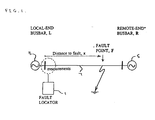
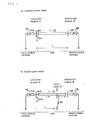
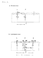
- Asingle-phase single-circuit double-end fed network of the form shown in Figure 2a) is taken as the overall unfaulted system model.
- the source networks, at the local- and remote-ends, are represented by their thevenin equivalents and the line is represented by a lumped parameter model.
- Applying a resistive fault to the Figure 2a) system at some distance, x from the local-end busbar, a faulted system model as shown in Figure 2b) is achieved.
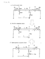
- a faulted system model as shown in Figure 3a
- This process of decomposition is shown again, but in an alternative and more detailed form, in Figure 8. Note that the following new symbols have been introduced.
- the pre-fault circuit is forced with the measured values for the pre-fault current at local-end busbar, Ipre, and the pre-fault voltage at local-end busbar, Vpre.
- the pre-fault and post-fault current and voltages are the steady-state power-frequency voltage and current phasors, measured at the local-end busbar in the actual system before and after the fault, as illustrated in Figure 2.
- the unknown fault resistance, Rf, in the superimposed circuit is replaced with a fault impedance, Zf.
- the fault position is assumed at different positions, F', along the entire line length. That is the fault distance, x', is assumed for a range of values from zero up to the total line length, L.
- the fault impedance, Zf is calculated. The foregoing is summarised in Figure 5.
- the fault impedance Zf is calculated using steady-state analytical techniques as will now be explained.
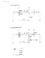
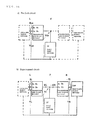
- the pre-fault and superimposed circuits used to calculate the fault impedance Zf are shown in Figures 9 and 10.
- the former shows the actual circuits and the latter the equivalent two-port representation.
- the calculation of the fault impedance Zf involves calculating the fault current If, the superimposed fault point voltage Vf, the pre-fault fault point voltage Vfss and the superimposed back injecting fault point generator driving voltage Ef. The calculation of these values and the subsequent calculation of the fault impedance Zf is as follows.
- the pre-fault fault point voltage Vfss is found using the pre-fault circuit shown in Figure 9a). Considering the two-port representation of the pre-fault circuit in Figure 10a) and applying two-port network theory we can obtain the following equation:-
- the superimposed back injecting fault point generator driving voltage Ef is equal and opposite to the pre-fault fault point voltage Vfss.
- the actual fault distance x is identified as that assumed fault distance for which the argument of Zf equals (or tends towards) zero. This is based on the tested observation that only when the assumed fault position F' is at the actual fault position F does the calculated fault impedance Zf become a purely real (resistive) value.
- the complete method, as given here, is summarised in Figure 6.
- the method is the same as has been applied in the single-phase case, with the exception that the single fault impedance to be calculated has become a network of inter-phase and phase-to- earth fault impedances. Any one of these fault impedances can be calculated and its argument used to pinpoint the fault position.
- the fault impedance network is not solvable for the general case, the fault type needs to be identified so that one of the fault impedances can be calculated correctly.
- Identifying the fault type involves determining the form of the fault point network. To do this a range of fault networks are assumed and the fault impedances, assumed to be involved, calculated. The actual form of the fault network is identified by the calculated fault impedances, involved, sharing the same assumed fault distance at which their arguments tend towards zero. This is basically the same idea as has been employed in the fault location, except it is now applied to fault type identification.
- Figure 7 illustrates this method of fault type identification, showing an actual fault point network, two assumed fault point networks, one correct the other incorrect, and the variation of the calculated fault impedance arguments with assumed fault distance for each assumed network.
Landscapes
- Physics & Mathematics (AREA)
- General Physics & Mathematics (AREA)
- Locating Faults (AREA)
Applications Claiming Priority (2)
| Application Number | Priority Date | Filing Date | Title |
|---|---|---|---|
| GB9401467A GB2286088B (en) | 1994-01-26 | 1994-01-26 | A method of locating the position of a fault on a power transmission line |
| GB9401467 | 1994-01-26 |
Publications (2)
| Publication Number | Publication Date |
|---|---|
| EP0665441A2 true EP0665441A2 (de) | 1995-08-02 |
| EP0665441A3 EP0665441A3 (de) | 1996-05-15 |
Family
ID=10749347
Family Applications (1)
| Application Number | Title | Priority Date | Filing Date |
|---|---|---|---|
| EP95300178A Withdrawn EP0665441A3 (de) | 1994-01-26 | 1995-01-12 | Verfahren zum Lokalisieren des Ortes eines Fehlers auf einer Energieübertragungsleitung. |
Country Status (6)
| Country | Link |
|---|---|
| US (1) | US5825189A (de) |
| EP (1) | EP0665441A3 (de) |
| AU (1) | AU685887B2 (de) |
| CA (1) | CA2140381A1 (de) |
| GB (1) | GB2286088B (de) |
| ZA (1) | ZA95370B (de) |
Cited By (3)
| Publication number | Priority date | Publication date | Assignee | Title |
|---|---|---|---|---|
| WO1999032894A1 (en) * | 1997-12-22 | 1999-07-01 | Abb Ab | Location of fault on series-compensated power transmission lines |
| EP1020729A3 (de) * | 1999-01-13 | 2001-07-18 | Alstom UK Limited | Fehlererkennung an Versorgungsleitungen |
| EP3563162A4 (de) * | 2016-12-30 | 2020-08-19 | ABB Power Grids Switzerland AG | Verfahren und steuerungssystem für fehlerphasendetektion |
Families Citing this family (29)
| Publication number | Priority date | Publication date | Assignee | Title |
|---|---|---|---|---|
| DE19746200C2 (de) * | 1997-10-18 | 2001-06-28 | Beha C Gmbh | Verfahren zur Bestimmung des Schleifenwiderstands eines Stromversorgungsnetzes |
| ATA194698A (de) * | 1998-11-20 | 2001-11-15 | Adaptive Regelsysteme Ges M B | Verfahren zur bestimmung des erdschlussbehafteten abzweiges |
| US6256592B1 (en) * | 1999-02-24 | 2001-07-03 | Schweitzer Engineering Laboratories, Inc. | Multi-ended fault location system |
| SE519943C2 (sv) * | 2000-12-14 | 2003-04-29 | Abb Ab | Metod för fellokalisering i en transmissionlinje |
| US6476613B2 (en) * | 2000-12-20 | 2002-11-05 | Abb Ab | Method of fault location in parallel transmission lines with series compensation |
| US6466030B2 (en) * | 2000-12-29 | 2002-10-15 | Abb Power Automation Ltd. | Systems and methods for locating faults on a transmission line with a single tapped load |
| US6466031B1 (en) | 2000-12-29 | 2002-10-15 | Abb Power Automation Ltd. | Systems and methods for locating faults on a transmission line with multiple tapped loads |
| GB2375242A (en) * | 2001-05-03 | 2002-11-06 | Alstom | Protecting a section of an electrical power line |
| US6879917B2 (en) * | 2002-06-14 | 2005-04-12 | Progress Energy Carolinas Inc. | Double-ended distance-to-fault location system using time-synchronized positive-or negative-sequence quantities |
| AT413769B (de) * | 2002-06-26 | 2006-05-15 | Adaptive Regelsysteme Gmbh | Verfahren zur bestimmung eines parameters eines elektrischen netzes |
| US7535233B2 (en) * | 2004-07-15 | 2009-05-19 | Cooper Technologies Company | Traveling wave based relay protection |
| US20060152866A1 (en) * | 2005-01-13 | 2006-07-13 | Gabriel Benmouyal | System for maintaining fault-type selection during an out-of-step condition |
| US7286963B2 (en) * | 2005-12-30 | 2007-10-23 | Abb Technology Ltd. | Method and device for fault location on three terminal power line |
| US7638999B2 (en) * | 2006-04-07 | 2009-12-29 | Cooper Technologies Company | Protective relay device, system and methods for Rogowski coil sensors |
| US20080125984A1 (en) * | 2006-09-25 | 2008-05-29 | Veselin Skendzic | Spatially Assisted Fault Reporting Method, System and Apparatus |
| US7564233B2 (en) * | 2006-11-06 | 2009-07-21 | Cooper Technologies Company | Shielded Rogowski coil assembly and methods |
| US7738221B2 (en) | 2007-12-07 | 2010-06-15 | Cooper Technologies Company | Transformer inrush current detector |
| US8941387B2 (en) * | 2010-10-12 | 2015-01-27 | Howard University | Apparatus and method for fault detection and location determination |
| GB201120477D0 (en) * | 2011-11-28 | 2012-01-11 | Univ Nottingham | Fault location in power distribution systems |
| US10401417B2 (en) * | 2013-02-13 | 2019-09-03 | General Electric Technology Gmbh | Electrical fault location determination in a distribution system based on phasor information |
| CA2932899C (en) * | 2013-12-06 | 2019-06-18 | Abb Inc. | Systems and methods for identifying faulted segments in multiphase power networks |
| CN104376210A (zh) * | 2014-11-17 | 2015-02-25 | 国网安徽省电力公司 | 基于ems单端量测的高压输电线路理论线损计算方法 |
| CN104965156B (zh) * | 2015-06-30 | 2018-02-09 | 昆明理工大学 | 一种利用极线故障电压进行pca聚类分析的故障选极方法 |
| BR102015021673B1 (pt) * | 2015-09-04 | 2022-07-05 | Universidade Estadual De Campinas – Unicamp | Método de proteção de distância para linhas de meio comprimento de onda e uso do mesmo |
| WO2019186490A1 (en) * | 2018-03-31 | 2019-10-03 | Abb Schweiz Ag | Method and device for protection in a multi-terminal power transmission system |
| WO2020194521A1 (ja) * | 2019-03-26 | 2020-10-01 | 日本電気株式会社 | 事故点標定装置、事故点標定システム、事故点標定方法、及び非一時的なコンピュータ可読媒体 |
| CN112269144A (zh) * | 2020-10-14 | 2021-01-26 | 西安热工研究院有限公司 | 风力发电输电系统线路单相接地故障定位方法 |
| CN115219846B (zh) * | 2022-07-12 | 2025-11-21 | 广州地铁设计研究院股份有限公司 | 一种复线直供牵引网故障定位方法、电力仪表及介质 |
| CN119291390B (zh) * | 2024-12-02 | 2025-12-16 | 国网湖南省电力有限公司 | 一种考虑分布式电源接入的配电网故障区段定位方法及系统 |
Family Cites Families (14)
| Publication number | Priority date | Publication date | Assignee | Title |
|---|---|---|---|---|
| JPS5240746A (en) * | 1975-09-25 | 1977-03-29 | Tokyo Electric Power Co Inc:The | Failure point measuring method |
| JPS5829471B2 (ja) * | 1978-10-30 | 1983-06-22 | 東京電力株式会社 | 事故点判別方式 |
| JPS58168976A (ja) * | 1982-03-31 | 1983-10-05 | Toshiba Corp | 故障点標定方式 |
| SE433405B (sv) * | 1982-09-14 | 1984-05-21 | Asea Ab | Forfarande och anordning for lokalisering av ett felstelle pa en trefasig kraftledning |
| JPS6240019A (ja) * | 1985-08-13 | 1987-02-21 | 三菱電機株式会社 | デジタル距離継電方式 |
| EP0224089B1 (de) * | 1985-11-07 | 1990-05-02 | Kabushiki Kaisha Toshiba | Einrichtung zur Dateninformationsabgabe für ein elektrisches Energienetz |
| SE449796B (sv) * | 1985-12-20 | 1987-05-18 | Asea Ab | Forfarande och anordning for lokalisering av fel pa en kraftledning |
| SE451102B (sv) * | 1985-12-20 | 1987-08-31 | Asea Ab | Forfarande for detektering av hogresistivt jordfel pa en kraftledning belegen mellan tva stationer samt anordning for genomforande av det nemnda forfarandet |
| US4767996A (en) * | 1986-01-20 | 1988-08-30 | Kabushiki Kaisha Toshiba | Fault current detection device for a D.C. network |
| EP0459522B1 (de) * | 1990-05-31 | 1995-12-20 | Nissin Electric Company, Limited | Fehlerlokalisierungsverfahren paralleler Doppelübertragungsleitungen mit N-Ausgängen |
| JP2563647B2 (ja) * | 1990-06-12 | 1996-12-11 | 関西電力株式会社 | 平行2回線電力系統用事故点標定方式 |
| JPH05672A (ja) * | 1991-06-24 | 1993-01-08 | Toyoda Gosei Co Ltd | ステアリングホイール芯金 |
| SE9201972L (sv) * | 1992-06-26 | 1993-11-29 | Asea Brown Boveri | Förfarande och anordning för att bestämma den felström som uppstår vid ett fel på kraftlinjer vid kortslutning mellan fas/faser till jord |
| JP3356484B2 (ja) * | 1992-06-30 | 2002-12-16 | 株式会社東芝 | 事故点標定装置 |
-
1994
- 1994-01-26 GB GB9401467A patent/GB2286088B/en not_active Expired - Fee Related
-
1995
- 1995-01-12 EP EP95300178A patent/EP0665441A3/de not_active Withdrawn
- 1995-01-17 ZA ZA95370A patent/ZA95370B/xx unknown
- 1995-01-17 CA CA002140381A patent/CA2140381A1/en not_active Abandoned
- 1995-01-24 AU AU11367/95A patent/AU685887B2/en not_active Ceased
-
1996
- 1996-08-13 US US08/696,115 patent/US5825189A/en not_active Expired - Fee Related
Cited By (4)
| Publication number | Priority date | Publication date | Assignee | Title |
|---|---|---|---|---|
| WO1999032894A1 (en) * | 1997-12-22 | 1999-07-01 | Abb Ab | Location of fault on series-compensated power transmission lines |
| US6529010B1 (en) | 1997-12-22 | 2003-03-04 | Abb Ab | Location of fault on series-compensated power transmission lines |
| EP1020729A3 (de) * | 1999-01-13 | 2001-07-18 | Alstom UK Limited | Fehlererkennung an Versorgungsleitungen |
| EP3563162A4 (de) * | 2016-12-30 | 2020-08-19 | ABB Power Grids Switzerland AG | Verfahren und steuerungssystem für fehlerphasendetektion |
Also Published As
| Publication number | Publication date |
|---|---|
| AU1136795A (en) | 1995-08-03 |
| CA2140381A1 (en) | 1995-07-27 |
| AU685887B2 (en) | 1998-01-29 |
| US5825189A (en) | 1998-10-20 |
| EP0665441A3 (de) | 1996-05-15 |
| GB2286088B (en) | 1997-09-24 |
| GB2286088A (en) | 1995-08-02 |
| GB9401467D0 (en) | 1994-03-23 |
| ZA95370B (en) | 1995-09-21 |
Similar Documents
| Publication | Publication Date | Title |
|---|---|---|
| EP0665441A2 (de) | Verfahren zum Lokalisieren des Ortes eines Fehlers auf einer Energieübertragungsleitung | |
| EP1172660B1 (de) | Verfahren und Vorrichtung zur Fehlerortung in Versorgungsnetzen | |
| EP2017632B1 (de) | Verfahren zur Fehlererkennung in unkompensierten Stromleitungen mit unsynchronisierter Zwei-Enden-Messung | |
| Das et al. | A fault locator for radial subtransmission and distribution lines | |
| de Morais Pereira et al. | Fault location in transmission lines using one-terminal postfault voltage data | |
| EP1992954B1 (de) | Verfahren zur Ortung eines einpoligen Erdschlusses | |
| Saha et al. | Review of fault location techniques for distribution systems | |
| CN101207281B (zh) | 多端故障定位系统 | |
| DE3687451T2 (de) | Methode zur ortung eines fehlers bei einer energieleitung und vorrichtung zur durchfuehrung der methode. | |
| Lawrence et al. | Development of an advanced transmission line fault location system. II. Algorithm development and simulation | |
| EP2000811A1 (de) | Verfahren zur Ortung eines einpoligen Erdschlusses | |
| Aggarwal et al. | An interactive approach to fault location on overhead distribution lines with load taps | |
| Saha et al. | Fault location method for MV cable network | |
| Ahn et al. | An accurate fault location algorithm for double-circuit transmission systems | |
| WO2019166903A1 (en) | Method and device for fault location in a two-terminal transmission system | |
| Pereira et al. | Optimization algorithm for fault location in transmission lines considering current transformers saturation | |
| Sachdev et al. | Determining locations of faults in distribution systems | |
| Saber | PMU–Based fault location method for Three–terminal transmission lines with outage of one line branch | |
| Firouzjah et al. | A current independent method based on synchronized voltage measurement for fault location on transmission lines | |
| Balcerek et al. | Improved unsynchronized two-end algorithm for locating faults in power transmission lines | |
| Popovic | A digital fault-location algorithm taking into account the imaginary part of the grounding impedance at the fault place | |
| Izykowski et al. | Fault location in three-terminal line with use of limited measurements | |
| Naidu et al. | A new approach for fault location on modern distribution systems with integrated DER | |
| Fulczyk et al. | Two-end unsynchronized fault location algorithm for double-circuit series compensated lines | |
| EP4276480A1 (de) | Verfahren und schutzgerät zum erkennen eines einphasigen erdschlusses |
Legal Events
| Date | Code | Title | Description |
|---|---|---|---|
| PUAI | Public reference made under article 153(3) epc to a published international application that has entered the european phase |
Free format text: ORIGINAL CODE: 0009012 |
|
| AK | Designated contracting states |
Kind code of ref document: A2 Designated state(s): AT BE CH DE DK ES FR GB GR IE IT LI LU MC NL PT SE |
|
| RAX | Requested extension states of the european patent have changed |
Free format text: LT PAYMENT 950202;SI PAYMENT 950202 |
|
| PUAL | Search report despatched |
Free format text: ORIGINAL CODE: 0009013 |
|
| AK | Designated contracting states |
Kind code of ref document: A3 Designated state(s): AT BE CH DE DK ES FR GB GR IE IT LI LU MC NL PT SE |
|
| AX | Request for extension of the european patent |
Free format text: LT PAYMENT 950202;SI PAYMENT 950202 |
|
| 17P | Request for examination filed |
Effective date: 19961105 |
|
| RAP1 | Party data changed (applicant data changed or rights of an application transferred) |
Owner name: ALSTOM UK LTD |
|
| STAA | Information on the status of an ep patent application or granted ep patent |
Free format text: STATUS: THE APPLICATION HAS BEEN WITHDRAWN |
|
| 18W | Application withdrawn |
Withdrawal date: 20011016 |