EP0665802B1 - Behälter mit einem daran befestigten wiederverschliessbaren Aussgiesser. - Google Patents
Behälter mit einem daran befestigten wiederverschliessbaren Aussgiesser. Download PDFInfo
- Publication number
- EP0665802B1 EP0665802B1 EP92922948A EP92922948A EP0665802B1 EP 0665802 B1 EP0665802 B1 EP 0665802B1 EP 92922948 A EP92922948 A EP 92922948A EP 92922948 A EP92922948 A EP 92922948A EP 0665802 B1 EP0665802 B1 EP 0665802B1
- Authority
- EP
- European Patent Office
- Prior art keywords
- container
- stem
- wall
- flange member
- outwardly
- Prior art date
- Legal status (The legal status is an assumption and is not a legal conclusion. Google has not performed a legal analysis and makes no representation as to the accuracy of the status listed.)
- Expired - Lifetime
Links
- 238000000034 method Methods 0.000 claims description 17
- 239000000853 adhesive Substances 0.000 claims description 15
- 230000001070 adhesive effect Effects 0.000 claims description 15
- 239000000463 material Substances 0.000 claims description 8
- 230000007423 decrease Effects 0.000 claims description 2
- 230000002093 peripheral effect Effects 0.000 claims description 2
- 230000004888 barrier function Effects 0.000 description 7
- 230000015572 biosynthetic process Effects 0.000 description 4
- 230000003292 diminished effect Effects 0.000 description 3
- 239000007788 liquid Substances 0.000 description 3
- 238000010276 construction Methods 0.000 description 2
- JXSJBGJIGXNWCI-UHFFFAOYSA-N diethyl 2-[(dimethoxyphosphorothioyl)thio]succinate Chemical compound CCOC(=O)CC(SP(=S)(OC)OC)C(=O)OCC JXSJBGJIGXNWCI-UHFFFAOYSA-N 0.000 description 2
- 238000007789 sealing Methods 0.000 description 2
- 241001125929 Trisopterus luscus Species 0.000 description 1
- 239000011248 coating agent Substances 0.000 description 1
- 238000000576 coating method Methods 0.000 description 1
- 239000012141 concentrate Substances 0.000 description 1
- 239000012611 container material Substances 0.000 description 1
- 230000003467 diminishing effect Effects 0.000 description 1
- 230000002401 inhibitory effect Effects 0.000 description 1
- 238000004519 manufacturing process Methods 0.000 description 1
- 239000006223 plastic coating Substances 0.000 description 1
- 230000003449 preventive effect Effects 0.000 description 1
- 239000000565 sealant Substances 0.000 description 1
Images

Classifications
-
- B—PERFORMING OPERATIONS; TRANSPORTING
- B65—CONVEYING; PACKING; STORING; HANDLING THIN OR FILAMENTARY MATERIAL
- B65D—CONTAINERS FOR STORAGE OR TRANSPORT OF ARTICLES OR MATERIALS, e.g. BAGS, BARRELS, BOTTLES, BOXES, CANS, CARTONS, CRATES, DRUMS, JARS, TANKS, HOPPERS, FORWARDING CONTAINERS; ACCESSORIES, CLOSURES, OR FITTINGS THEREFOR; PACKAGING ELEMENTS; PACKAGES
- B65D5/00—Rigid or semi-rigid containers of polygonal cross-section, e.g. boxes, cartons or trays, formed by folding or erecting one or more blanks made of paper
- B65D5/42—Details of containers or of foldable or erectable container blanks
- B65D5/72—Contents-dispensing means
- B65D5/74—Spouts
- B65D5/746—Spouts formed separately from the container
Definitions
- the present invention pertains to a pour spout and more particularly, to a container having a reclosable pour spout attached thereto.
- U.S. Patent No. 4,813,578 discloses a pour spout provided with a flange portion for attaching the pour spout to the exterior surface of a container.
- the flange portion of the pour spout is attached to the exterior surface by heat sealing the plastic material from which the pour spout is fabricated to the plastic outer coating on the container.
- Such an arrangement is susceptible to certain improvements because it has been found that the securement of the pour spout to the container may deteriorate somewhat over time.
- the plastic layer on the container has a tendency to undergo additional curing or other changes.
- the adhesion at the interface between the flange portion of the pour spout and the outer surface of the container may be affected and diminished slightly, e.g., the plastic coating on the container may shrink slightly relative to the flange portion of the pour spout.
- U.S. Patent No. 4,909,434 discloses a method of securing a pouring spout in liquid-tight relation to the innermost and outermost surfaces of a carton.
- the pouring spout is provided with a preformed first flange and a liquid passageway oriented substantially perpendicular to the first flange.
- the pouring spout is mounted on the carton by inserting the liquid passageway of the pouring spout through a hole that is cut in the carton wall.
- the first flange is brought into contacting relation with the outer surface of the carton wall while the liquid passageway is deformed to form a second flange parallel to the first flange and lying flat on the interior surface of the carton wall.
- U.S. Patent No. 5,069,385 discloses a similar method for securing a pouring spout to the innermost and outermost surfaces of a carton. As shown in particular in Figs 18 and 19, a spout having a preformed external flange is assembled on a carton and an internal flange is formed so as to lie flat against the interior surface of the carton parallel to the external flange.
- the present invention provides a pour spout that is attached to the container in a manner that is well suited for helping to ensure that the pout spout remains reliably and securely attached to the container and is not easily pulled from the container.
- the present invention is directed to a container having a pour spout attached thereto, generally of the type disclosed in U.S. Patent No. 4,909,434.
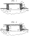
- the reclosable pour spout 10 embodying the present invention includes a base member 12 and a cap 14.
- the cap 14 may be integrally connected to and formed in one piece with the base member 12.
- the cap 14 can be connected to the cap 14 by way of a strip of connecting material 18.
- the base member 12 as illustrated in Fig. 4 is defined by a substantially planar flange member 20, an upwardly extending substantially cylindrical extension 24 and a downwardly extending substantially cylindrical stem 26.
- the cylindrical extension 24, the cylindrical stem 26 and the flange member 20 are all formed integrally and in one piece from a suitable plastic material.
- the stem 26 can have a substantially constant thickness along its length.
- the extension 24 and the stem 26 together define a hollow cylindrical portion and the flange member 20 surrounds that cylindrical portion at a point intermediate the ends of the cylindrical portion.
- the inner surface of the cap 14 and the outer peripheral surface of the cylindrical extension 24 interact with one another in the manner illustrated in Fig. 2.
- the extension 24 is provided with an annular ridge 32 and an annular recess 34 while the inner surface of the cap 14 is provided with an outwardly tapering part 36 that cooperates with the annular ridge 32 and the annular recess 34.
- annular barrier strip 38 is provided on the exterior surface of the cylindrical stem 26.
- the annular strip 38 functions as a barrier for inhibiting the adhesive from flowing beyond the barrier 38.
- the annular barrier strip 38 can be seen in the perspective view of Fig. 4.
- the cylindrical stem 26 is provided with oppositely positioned and generally V-shaped cutout portions 40.
- the portion of the stem 26 below the barrier strip 38 and extending away from the flange member has a reduced thickness accomplished by maintaining the interior dimension identical with the remainder of the stem 26.
- the generally V-shaped cutout portions 40 help facilitate the process of forming the stem 26 from the initial configuration shown in Fig. 4 to the final configuration depicted in Fig. 2 in which the pour spout 10 is mounted on the container 100.
- pour spout being mounted or secured to a container or a container body is meant to include the pour spout being attached to a container, to a container blank prior to formation into the container, and to a container blank in any intermediate stage of the container formation process.
- the pour spout 10 is placed on the container 100 by inserting the cylindrical stem 26 into the hole formed in the container 100. Thereafter, a suitably shaped plate is brought into contact with the free end 42 of the cylindrical stem 26 to cause a portion of the stem 26 to turn outwardly and form an outwardly turned portion 25, to turn slightly upwardly toward the wall of the container 100 to form an upwardly turned portion 27, and to turn outwardly again to form another outwardly turned portion 29.
- the outwardly turned portion 29 preferably extends somewhat parallel to the wall of the container 100.
- the outwardly turned portion 29 of the stem 26 is preferably in contact with the inner surface of the wall of the container 100.
- the free end 42 of the stem 26 could be turned upwardly slightly such that the free end 42 of the stem 26 is in contact with the inner surface of the wall of the container 100.
- the pour spout 10 By forming the stem 26 of the pour spout 10 relative to the container 100 in the manner illustrated in Fig. 2, the pour spout 10 is mechanically secured in place on the container 100.
- an upwardly directed force is applied to the pour spout 10, such as might occur upon opening of the cap 14 or if the container is picked up by the pour spout, the outwardly turned portion 29 of the stem 26 rests against the inner surface of the container 100 and tends to distribute the upwardly directed force across the surface of the container.
- the interface between the flange member 20 and the outer surface of the container 100 is altered slightly as a result of further curing of the plastic layer on the container, the ability of the pour spout to be pulled away from the container will be substantially inhibited.
- the embodiment of the pour spout shown in Fig. 1 is similar to that illustrated in Fig. 2 except that an annular ledge 30' is included that extends around the entire periphery of the cylindrical stem 26'.
- the annular ledge 30' is spaced from the bottom surface 28' of the flange member 20' by a distance that generally corresponds to the thickness of the container 100'.
- a hole is formed in the container to receive the stem 26' of the pour spout 10'. It can be readily appreciated that due to the nature of the material from which the container 100' is fabricated, the periphery of the hole in the container 100' can be displaced slightly in the plane of the material when the cylindrical stem 26' is inserted into the hole.
- the portion of the container wall surrounding the stem 26' becomes positioned between the ledge 30' and the bottom surface 28' of the flange member 20' in the manner illustrated in Fig. 1.
- the pour spout 10' is held in place relative to the container 100' in the axial direction so that the pour spout 10' can be securely attached to the container by suitable means.
- the ledge 30' helps to maintain the position of the pour spout 10' on the container 100' to help ensure that the pour spout 10' is securely attached to the container 100'.
- annular ledge 30' which extends completely around the outer periphery of the cylindrical stem 26' could be replaced with a plurality of spaced apart ledge segments extend around a portion of the cylindrical stem.
- an adhesive is applied between the bottom surface 28, 28' of the flange member 20, 20' and the facing outer surface of the container 100, 100'.
- two annular ridges 46, 46', 48, 48' are provided on the bottom surface 28, 28' of the flange member 20, 20'.
- annular ridge 48, 48' it may be desirable to eliminate the annular ridge 48, 48' so that adhesive can flow partially down the stem 26 to the annular barrier strip 38, 38' to aid sealing the hole in the container.
- additional adhesive/sealant can be applied to the stem 26 between the flange members 20, 20' and the annular barrier strip 38, 38' to accomplish essentially the same result while still preventing substantial adhesive in the interior of the carton.
- the annular ridges 46, 48 are also useful in helping to concentrate the adhesive in a confined annular area to thereby aid in proper securement of the pour spout 10. 10' to the container 100, 100'.
- FIG. 3 another embodiment of the reclosable pour spout of the present invention is illustrated.
- the integrally formed cap is not illustrated. However, it is to understood that the cap could be configured in the manner illustrated with respect to the embodiment shown in Figs. 1 and 2.
- the reclosable pour spout 50 includes a flange member 52, an axially upwardly extending and integrally formed cylindrical extension 54 and an integrally formed and axially downwardly extending cylindrical stem 56.
- the cylindrical extension 54 is shown as having a slightly different configuration then that illustrated with respect to the embodiments shown in Figs. 1 and 2, it is to be understood that the extension 54 could be configured in the same manner illustrated with respect to the embodiments shown in Figs. 1 and 2.
- the thickness of the cylindrical stem 56 can decrease from the flange member 52 to the free end 58 of the stem 56.
- the stem 56 is reduced in thickness to help facilitate the forming of the stem 56 in the manner necessary to result in the configuration shown in Fig. 3.
- the V-shaped notches are not provided in the stem 56.
- the stem 56 is unbroken such that, from the bottom surface of the flange member 52 to the free end 58 of the stem 56, the stem forms a complete cylindrical member.
- the securement of the embodiment of the reclosable attachment shown in Fig. 3 to the container is effected by inserting the cylindrical stem 56 into the hole in the container 200.
- An adhesive can be applied between the bottom surface of the flange member 52 and the outer surface of the container 200 to secure the pour spout 50 to the container.
- a tool can then be employed to form the cylindrical stem 56 into the configuration shown in Fig. 3.
- the tool is such that it causes the stem 56 to flair outwardly at a point 60 just below the flange member 52.
- This outward flaring of the stem 56 also causes the portion 62 of the container surrounding the hole periphery to flair downwardly toward the interior of the container and slightly outwardly, thereby defining a generally U-shaped crotch 61.
- the tool also causes a portion of the stem 56 to turn upwardly to define an upwardly turned portion 57.
- the upwardly turned portion 57 is turned in towards the stem 56 so that the free end 58 of the stem 56 fits into the generally U-shaped crotch 61 formed by the turning of the portion 62 of the container.
- the upwardly turned portion 57 of the stem could be turned slightly less than that illustrated in Fig. 3 so that the free end 58 of the stem 56 faces and is substantially in contact with the inner surface of the container wall.
- the upwardly turned portion 57 of the stem could be somewhat perpendicularly arranged with respect to the container wall.
- the portion of the stem 56 of the pour spout 50 that has been turned is substantially C-shaped in cross-section.
- the portion 62 of the container material surrounding the hole periphery is positioned within a substantially closed region 64 defined by the outwardly and upwardly turned portion of the stem 56.
- Such an arrangement can be advantageous in that any adhesive that may flow radially inwardly between the outer periphery of the stem 56 and the inner periphery of the hole in the container 200 will be prevented from flowing into the interior of the container and contaminating the contents in the container since it will be trapped within the enclosed region 64.
- the formation of the stem 56 of the pour spout 50 relative to the container 200 in the manner shown in Fig. 3 produces a pour spout 50 that, like the embodiments illustrated in Figs. 1 and 2, is mechanically secured in place on the container 200. Consequently, when an upwardly directed force is applied to the pour spout 50, such as might occur upon opening of the cap (not shown) or if the container 200 is picked up by the pour spout 50, the upwardly turned portion 57 of the stem 56 presses against the inner surface of the container 200, thereby resisting any tendency of the pour spout to be pulled out of the container 200.
- annular ridges similar to the annular ridges 46, 48 shown in Fig. 2 could be provided, if desired.
Landscapes
- Engineering & Computer Science (AREA)
- Mechanical Engineering (AREA)
- Closures For Containers (AREA)
Claims (16)
- Behälter zum Aufbewahren von gießbarem Material, mit:einem Behälterkörper (100, 200) mit einer Außenfläche, einer Innenfläche, einem Innenraum zur Aufnahme von gießbarem Material und einer eine Wand des Behälterkörpers durchlaufende Öffnung, die ein Ausleeren des Materials aus dem Behälter ermöglicht; undeinem wiederverschließbaren Ausgießer (10, 50), der an der Wand des Behälterkõrpers befestigt ist und aufweist:ein Flanschteil (20, 52) mit einander gegenüber angeordneten ersten und zweiten Seiten sowie einer es durchlaufenden Öffnung, wobei die zweite Seite des Flanschteils an der Außenfläche der Wand des Behälterkörpers befestigt ist;eine Verlängerung (24, 54), die mit der ersten Seite des Flanschteils verbunden ist, sich axial von dieser weg erstreckt und durch die eine Öffnung verläuft, die mit der Öffnung im Flanschteil in Verbindung steht; undeinen Steg (26, 56), der mit der zweiten Seite des Flanschteils verbunden ist, sich axial von dieser weg erstreckt und durch den eine Öffnung verläuft, die mit der Öffnung im Flanschteil in Verbindung steht, wobei der Steg einen im wesentlichen axial verlaufenden Abschnitt aufweist, der durch die Öffnung in der Wand des Behälterkörpers hindurchverläuft;
dadurch gekennzeichnet, daß:ein Abschnitt des im wesentlichen axial verlaufenden Abschnitts über die Innenfläche der Wand des Behälterkörpers hinaus zum Innenraum des Behälterkörpers verläuft; unddaß ein nach außen und nach oben gewandter Abschnitt (27, 57) sich von dem im wesentlichen axial verlaufenden Abschnitt aus zurück zur Innenfläche der Wand des Behälterkörpers erstreckt und eine Dicke aufweist, die geringer als die Dicke des im wesentlichen axial verlaufenden Abschnitts ist. - Behälter nach Anspruch 1, bei dem der nach oben gewandte Abschnitt (27) mit dem im wesentlichen axial verlaufenden Abschnitt durch einen nach außen gewandten Abschnitt (25) verbunden ist, wobei der Steg einen weiteren nach außen gewandten Abschnitt (29) aufweist, der benachbart zu dem nach oben gewandten Abschnitt (27) angeordnet ist und sich im wesentlichen parallel zur Innenfläche der Wand des Behälterkörpers (100) erstreckt.
- Behälter nach Anspruch 1 oder 2, bei dem der nach oben gewandte Abschnitt (27) des Stegs (26) mit dem im wesentlichen axial verlaufenden Abschnitt durch einen nach außen gewandten Abschnitt (25) verbunden ist, wobei in dem nach oben gewandten Abschnitt und in dem nach außen gewandten Abschnitt zwei Ausschnittsabschnitte (40) ausgebildet sind.
- Behälter nach Anspruch 1 oder 2, wobei der Steg frei von Ausschnittsabschnitten ist.
- Behälter nach einem der vorhergehenden Ansprüche, mit einer Ringleiste (30) um den Außenumfang des im wesentlichen axial verlaufenden Abschnitts des Stegs (26) herum, wobei die Leiste von dem Flanschteil (20) in einem Abstand angeordnet ist, der zum Berühren der Innenfläche der Wand des Behälterkörpers (100) ausreicht.
- Behälter nach Anspruch 1, bei dem ein die Öffnung umgebender Abschnitt (62) der Wand des Behälterkörpers (200) nach innen zum Innenraum des Behälters und nach außen gewandt ist, um dadurch eine Gabel (61) auszubilden, wobei der Steg (56) ein freies Ende (58) aufweist, das in die Gabel hineinpaßt.
- Behälter nach Anspruch 6, bei dem der die Öffnung in der Wand umschließende Abschnitt (62) der Wand des Behälterkörpers (200) durch den im wesentlichen axial verlaufenden Abschnitt des Stegs (56) nach innen zum Innenraum des Behälters und nach außen konisch erweitert ist.
- Behälter nach Anspruch 6 oder 7, bei dem die Dicke des Steges (56) vom Flanschteil zum freien Ende des Stegs hin abnimmt.
- Verfahren zum Versehen eines Behälters mit einem Ausgießer, mit den folgenden Schritten:Bereitstellen eines Ausgießers (10, 50) mit einem hohlen zylindrischen Abschnitt (24, 54) und einem ringförmigen Flanschteil (20, 52), das mit einer äußeren Umfangsfläche des zylindrischen Abschnitts verbunden ist und sich von dieser aus radial auswärts erstreckt und das zwischen einander gegenüberliegenden Enden des zylindrischen Abschnitts angeordnet ist, wobei der zylindrische Abschnitt einen Teil aufweist, der zwischen dem Flanschteil und einem Ende des zylindrischen Abschnitts angeordnet ist und einen Steg (26, 56) ausbildet;Bereitstellen eines Behälters (100, 200), in dessen einer Wand eine Öffnung ausgebildet ist und der Innen- und Außenflächen aufweist; undBefestigen des Ausgießers an dem Behälter durch Einsetzen des Steges in die Öffnung in der Behälterwand;
gekennzeichnet durch:Befestigen des Ausgießers an der Behälterwand, wobei ein im wesentlichen axial verlaufender Abschnitt des Steges (26, 56) über die Innenfläche der Behälterwand hinaus in den Innenraum des Behälters verläuft; undWenden eines mit einer reduzierten Dicke versehenen Abschnittes (27, 57) des im wesentlichen axial verlaufenden Stegabschnittes zur Außenseite des letzteren Stegabschnittes und zurück zur Innenfläche der Behälterwand, um einen nach oben gewandten Abschnitt (27, 57) des Steges auszubilden. - Verfahren nach Anspruch 9, mit dem Befestigen der Außenfläche der Behälterwand an einer Fläche des Flanschteiles (20, 52), die der Außenfläche der Behälterwand zugewandt ist.
- Verfahren nach Anspruch 10, bei dem die Fläche des Flanschteiles (20, 52) an der Außenfläche der Behälterwand durch ein Klebemittel befestigt wird.
- Verfahren nach Anspruch 9, 10 oder 11, bei dem der nach oben gewandte Abschnitt (27) des Steges ein freies Ende aufweist, und bei dem das Verfahren das Nachaußenwenden des nach oben gewandten Abschnittes (27) in der Nähe dessen freien Endes aufweist, um einen weiteren nach außen gewandten Abschnitt (29) des Steges auszubilden.
- Verfahren nach Anspruch 12, bei dem der weitere nach außen gewandte Abschnitt (29) des Steges ausgebildet wird, um im wesentlichen parallel zur Innenfläche der Behälterwand zu verlaufen.
- Verfahren nach Anspruch 13, bei dem der weitere nach außen gewandte Abschnitt (29) des Steges an der Innenfläche der Behälterwand anliegt.
- Verfahren nach Anspruch 9, bei dem ein die Öffnung umgebender Abschnitt (62) der Behälterwand nach innen zum Innenraum des Behälters und nach außen hin konisch erweitert wird, um dadurch eine Gabel (61) auszubilden, und bei dem der nach oben gewandte Abschnitt (57) des Steges derart gewendet wird, daß ein freies Ende (58) des Steges in die Gabel paßt.
- Verfahren nach Anspruch 15, mit dem Schritt des konischen Erweiterns des die Öffnung umgebenden Abschnitts (62) der Behälterwand nach innen durch Wenden des nach oben gewandten Stegabschnittes (57).
Priority Applications (1)
| Application Number | Priority Date | Filing Date | Title |
|---|---|---|---|
| AT92922948T ATE185331T1 (de) | 1992-10-20 | 1992-10-20 | Behälter mit einem daran befestigten wiederverschliessbaren aussgiesser. |
Applications Claiming Priority (4)
| Application Number | Priority Date | Filing Date | Title |
|---|---|---|---|
| US07/634,439 US5108029A (en) | 1990-02-16 | 1990-12-27 | Reclosable attachment for containers |
| PCT/US1991/000173 WO1991012181A1 (en) | 1990-02-16 | 1991-01-16 | Reclosable attachment for containers |
| US07/753,855 US5199635A (en) | 1990-02-16 | 1991-09-03 | Container having reclosable pour spout mounted thereon |
| PCT/US1992/009186 WO1994008858A1 (en) | 1990-12-27 | 1992-10-20 | Container having reclosable pour spout mounted thereon |
Publications (3)
| Publication Number | Publication Date |
|---|---|
| EP0665802A1 EP0665802A1 (de) | 1995-08-09 |
| EP0665802A4 EP0665802A4 (de) | 1996-07-31 |
| EP0665802B1 true EP0665802B1 (de) | 1999-10-06 |
Family
ID=27492436
Family Applications (1)
| Application Number | Title | Priority Date | Filing Date |
|---|---|---|---|
| EP92922948A Expired - Lifetime EP0665802B1 (de) | 1990-12-27 | 1992-10-20 | Behälter mit einem daran befestigten wiederverschliessbaren Aussgiesser. |
Country Status (4)
| Country | Link |
|---|---|
| EP (1) | EP0665802B1 (de) |
| AU (1) | AU2900692A (de) |
| DE (1) | DE69230113D1 (de) |
| WO (1) | WO1994008858A1 (de) |
Families Citing this family (3)
| Publication number | Priority date | Publication date | Assignee | Title |
|---|---|---|---|---|
| DE4325830A1 (de) * | 1993-07-31 | 1995-02-02 | Tetra Laval Holdings & Finance | Fließmittelverpackung mit Ausgießvorrichtung, Verfahren zur Herstellung einer Fließmittelverpackung und Werkzeug zur Durchführung des Verfahrens |
| DE102020117516A1 (de) * | 2020-07-02 | 2022-01-05 | Induflex Robert Morgan, eingetragener Kaufmann | Einsatzteil für eine Verpackungsöffnung und Verfahren zum Einsetzen eines Einsatzteils in eine Verpackungsöffnung |
| DE102021132092A1 (de) * | 2021-12-06 | 2023-06-07 | Induflex Robert Morgan, eingetragener Kaufmann | Einsatzteil für eine Verpackungsöffnung und Verfahren zum Einsetzen eines Einsatzteils in eine Verpackungsöffnung |
Family Cites Families (3)
| Publication number | Priority date | Publication date | Assignee | Title |
|---|---|---|---|---|
| US4909434A (en) * | 1988-05-20 | 1990-03-20 | The Procter & Gamble Company | Moisture impervious carton having one-piece pouring spout sealed to innermost and outermost surfaces |
| DE4015119A1 (de) * | 1989-07-10 | 1991-01-31 | Pkl Verpackungssysteme Gmbh | Quaderfoermige giebelpackung mit im bereich des flachdachs angebrachtem ausgiesser |
| US5169374A (en) * | 1991-12-03 | 1992-12-08 | Capitol Spouts, Inc. | Method and apparatus for securing a pouring spout to a container |
-
1992
- 1992-10-20 WO PCT/US1992/009186 patent/WO1994008858A1/en not_active Ceased
- 1992-10-20 AU AU29006/92A patent/AU2900692A/en not_active Abandoned
- 1992-10-20 EP EP92922948A patent/EP0665802B1/de not_active Expired - Lifetime
- 1992-10-20 DE DE69230113T patent/DE69230113D1/de not_active Expired - Lifetime
Also Published As
| Publication number | Publication date |
|---|---|
| AU2900692A (en) | 1994-05-09 |
| EP0665802A1 (de) | 1995-08-09 |
| DE69230113D1 (de) | 1999-11-11 |
| EP0665802A4 (de) | 1996-07-31 |
| WO1994008858A1 (en) | 1994-04-28 |
Similar Documents
| Publication | Publication Date | Title |
|---|---|---|
| US5199635A (en) | Container having reclosable pour spout mounted thereon | |
| US4529100A (en) | Container and sealed closure means | |
| EP0233270B1 (de) | Behälter | |
| US5108029A (en) | Reclosable attachment for containers | |
| EP0435279B1 (de) | Ausgiessspund für Flüssigkeitsbehälter aus Papier | |
| US4391385A (en) | Closing arrangement | |
| US4491224A (en) | Weldable tear-off capping film for sealing packages | |
| US5927532A (en) | Vapor-seal child resistant closure and container package | |
| US4183457A (en) | Shrink tape closure | |
| US4733787A (en) | Tamper evident overcap | |
| US5765747A (en) | Pour spout fitment for gable top container | |
| NO985114D0 (no) | Lukke for en beholder | |
| JPH0440269B2 (de) | ||
| US5927530A (en) | Angled tab closure liner | |
| IE903841A1 (en) | "Plastics cap for blow-moulded plastics containers" | |
| AU701488B2 (en) | Screw cap with welding ring | |
| CN1997560B (zh) | 瓶子密封件 | |
| US5320237A (en) | Sealed closure for drum | |
| US4817815A (en) | Container comprising cylindrical jacket and lid with closable vent and process for its production | |
| EP0312816A1 (de) | Ausguss für Flüssigkeitsbehälter | |
| US5779086A (en) | Sealing system and method for a twist-off can end assembly | |
| EP0181750A2 (de) | Wegwerfbehälter | |
| EP0665802B1 (de) | Behälter mit einem daran befestigten wiederverschliessbaren Aussgiesser. | |
| AU694878B2 (en) | Pouring attachment | |
| AU6734787A (en) | Inserts for fixing into openings |
Legal Events
| Date | Code | Title | Description |
|---|---|---|---|
| PUAI | Public reference made under article 153(3) epc to a published international application that has entered the european phase |
Free format text: ORIGINAL CODE: 0009012 |
|
| 17P | Request for examination filed |
Effective date: 19950502 |
|
| AK | Designated contracting states |
Kind code of ref document: A1 Designated state(s): AT BE CH DE DK ES FR GB GR IE IT LI LU MC NL SE |
|
| A4 | Supplementary search report drawn up and despatched |
Effective date: 19960614 |
|
| AK | Designated contracting states |
Kind code of ref document: A4 Designated state(s): AT BE CH DE DK ES FR GB GR IE IT LI LU MC NL SE |
|
| 17Q | First examination report despatched |
Effective date: 19970110 |
|
| GRAG | Despatch of communication of intention to grant |
Free format text: ORIGINAL CODE: EPIDOS AGRA |
|
| GRAG | Despatch of communication of intention to grant |
Free format text: ORIGINAL CODE: EPIDOS AGRA |
|
| GRAH | Despatch of communication of intention to grant a patent |
Free format text: ORIGINAL CODE: EPIDOS IGRA |
|
| GRAH | Despatch of communication of intention to grant a patent |
Free format text: ORIGINAL CODE: EPIDOS IGRA |
|
| RAP1 | Party data changed (applicant data changed or rights of an application transferred) |
Owner name: PORTOLA PACKAGING, INC. |
|
| GRAH | Despatch of communication of intention to grant a patent |
Free format text: ORIGINAL CODE: EPIDOS IGRA |
|
| GRAA | (expected) grant |
Free format text: ORIGINAL CODE: 0009210 |
|
| AK | Designated contracting states |
Kind code of ref document: B1 Designated state(s): AT BE CH DE DK ES FR GB GR IE IT LI LU MC NL SE |
|
| PG25 | Lapsed in a contracting state [announced via postgrant information from national office to epo] |
Ref country code: SE Free format text: THE PATENT HAS BEEN ANNULLED BY A DECISION OF A NATIONAL AUTHORITY Effective date: 19991006 Ref country code: NL Free format text: LAPSE BECAUSE OF FAILURE TO SUBMIT A TRANSLATION OF THE DESCRIPTION OR TO PAY THE FEE WITHIN THE PRESCRIBED TIME-LIMIT Effective date: 19991006 Ref country code: LI Free format text: LAPSE BECAUSE OF FAILURE TO SUBMIT A TRANSLATION OF THE DESCRIPTION OR TO PAY THE FEE WITHIN THE PRESCRIBED TIME-LIMIT Effective date: 19991006 Ref country code: GR Free format text: LAPSE BECAUSE OF NON-PAYMENT OF DUE FEES Effective date: 19991006 Ref country code: FR Free format text: LAPSE BECAUSE OF FAILURE TO SUBMIT A TRANSLATION OF THE DESCRIPTION OR TO PAY THE FEE WITHIN THE PRESCRIBED TIME-LIMIT Effective date: 19991006 Ref country code: ES Free format text: THE PATENT HAS BEEN ANNULLED BY A DECISION OF A NATIONAL AUTHORITY Effective date: 19991006 Ref country code: CH Free format text: LAPSE BECAUSE OF FAILURE TO SUBMIT A TRANSLATION OF THE DESCRIPTION OR TO PAY THE FEE WITHIN THE PRESCRIBED TIME-LIMIT Effective date: 19991006 Ref country code: BE Free format text: LAPSE BECAUSE OF FAILURE TO SUBMIT A TRANSLATION OF THE DESCRIPTION OR TO PAY THE FEE WITHIN THE PRESCRIBED TIME-LIMIT Effective date: 19991006 Ref country code: AT Free format text: LAPSE BECAUSE OF FAILURE TO SUBMIT A TRANSLATION OF THE DESCRIPTION OR TO PAY THE FEE WITHIN THE PRESCRIBED TIME-LIMIT Effective date: 19991006 |
|
| REF | Corresponds to: |
Ref document number: 185331 Country of ref document: AT Date of ref document: 19991015 Kind code of ref document: T |
|
| REG | Reference to a national code |
Ref country code: CH Ref legal event code: EP |
|
| PG25 | Lapsed in a contracting state [announced via postgrant information from national office to epo] |
Ref country code: LU Free format text: LAPSE BECAUSE OF NON-PAYMENT OF DUE FEES Effective date: 19991020 |
|
| PGFP | Annual fee paid to national office [announced via postgrant information from national office to epo] |
Ref country code: GB Payment date: 19991110 Year of fee payment: 8 |
|
| REF | Corresponds to: |
Ref document number: 69230113 Country of ref document: DE Date of ref document: 19991111 |
|
| PGFP | Annual fee paid to national office [announced via postgrant information from national office to epo] |
Ref country code: IE Payment date: 19991217 Year of fee payment: 8 |
|
| ITF | It: translation for a ep patent filed | ||
| PG25 | Lapsed in a contracting state [announced via postgrant information from national office to epo] |
Ref country code: DK Free format text: LAPSE BECAUSE OF FAILURE TO SUBMIT A TRANSLATION OF THE DESCRIPTION OR TO PAY THE FEE WITHIN THE PRESCRIBED TIME-LIMIT Effective date: 20000106 |
|
| PG25 | Lapsed in a contracting state [announced via postgrant information from national office to epo] |
Ref country code: DE Free format text: LAPSE BECAUSE OF FAILURE TO SUBMIT A TRANSLATION OF THE DESCRIPTION OR TO PAY THE FEE WITHIN THE PRESCRIBED TIME-LIMIT Effective date: 20000108 |
|
| REG | Reference to a national code |
Ref country code: IE Ref legal event code: FG4D |
|
| NLV1 | Nl: lapsed or annulled due to failure to fulfill the requirements of art. 29p and 29m of the patents act | ||
| EN | Fr: translation not filed | ||
| REG | Reference to a national code |
Ref country code: CH Ref legal event code: PL |
|
| PG25 | Lapsed in a contracting state [announced via postgrant information from national office to epo] |
Ref country code: MC Free format text: LAPSE BECAUSE OF NON-PAYMENT OF DUE FEES Effective date: 20000430 |
|
| PLBE | No opposition filed within time limit |
Free format text: ORIGINAL CODE: 0009261 |
|
| STAA | Information on the status of an ep patent application or granted ep patent |
Free format text: STATUS: NO OPPOSITION FILED WITHIN TIME LIMIT |
|
| 26N | No opposition filed | ||
| PG25 | Lapsed in a contracting state [announced via postgrant information from national office to epo] |
Ref country code: IE Free format text: LAPSE BECAUSE OF NON-PAYMENT OF DUE FEES Effective date: 20001020 Ref country code: GB Free format text: LAPSE BECAUSE OF NON-PAYMENT OF DUE FEES Effective date: 20001020 |
|
| GBPC | Gb: european patent ceased through non-payment of renewal fee |
Effective date: 20001020 |
|
| REG | Reference to a national code |
Ref country code: IE Ref legal event code: MM4A |
|
| PG25 | Lapsed in a contracting state [announced via postgrant information from national office to epo] |
Ref country code: IT Free format text: LAPSE BECAUSE OF NON-PAYMENT OF DUE FEES Effective date: 20051020 |