EP0666018B1 - Vorrichtung zur automatischen Befüllung von Ladebehältern - Google Patents
Vorrichtung zur automatischen Befüllung von Ladebehältern Download PDFInfo
- Publication number
- EP0666018B1 EP0666018B1 EP95100930A EP95100930A EP0666018B1 EP 0666018 B1 EP0666018 B1 EP 0666018B1 EP 95100930 A EP95100930 A EP 95100930A EP 95100930 A EP95100930 A EP 95100930A EP 0666018 B1 EP0666018 B1 EP 0666018B1
- Authority
- EP
- European Patent Office
- Prior art keywords
- discharge
- evaluation
- measuring device
- range
- flap
- Prior art date
- Legal status (The legal status is an assumption and is not a legal conclusion. Google has not performed a legal analysis and makes no representation as to the accuracy of the status listed.)
- Expired - Lifetime
Links
Images








Classifications
-
- B—PERFORMING OPERATIONS; TRANSPORTING
- B65—CONVEYING; PACKING; STORING; HANDLING THIN OR FILAMENTARY MATERIAL
- B65G—TRANSPORT OR STORAGE DEVICES, e.g. CONVEYORS FOR LOADING OR TIPPING, SHOP CONVEYOR SYSTEMS OR PNEUMATIC TUBE CONVEYORS
- B65G69/00—Auxiliary measures taken, or devices used, in connection with loading or unloading
- B65G69/04—Spreading out the materials conveyed over the whole surface to be loaded; Trimming heaps of loose materials
- B65G69/0408—Spreading out the materials conveyed over the whole surface to be loaded; Trimming heaps of loose materials by relatively moving an endless feeding means
-
- A—HUMAN NECESSITIES
- A01—AGRICULTURE; FORESTRY; ANIMAL HUSBANDRY; HUNTING; TRAPPING; FISHING
- A01D—HARVESTING; MOWING
- A01D43/00—Mowers combined with apparatus performing additional operations while mowing
- A01D43/06—Mowers combined with apparatus performing additional operations while mowing with means for collecting, gathering or loading mown material
- A01D43/07—Mowers combined with apparatus performing additional operations while mowing with means for collecting, gathering or loading mown material in or into a trailer
- A01D43/073—Mowers combined with apparatus performing additional operations while mowing with means for collecting, gathering or loading mown material in or into a trailer with controllable discharge spout
-
- A—HUMAN NECESSITIES
- A01—AGRICULTURE; FORESTRY; ANIMAL HUSBANDRY; HUNTING; TRAPPING; FISHING
- A01D—HARVESTING; MOWING
- A01D43/00—Mowers combined with apparatus performing additional operations while mowing
- A01D43/08—Mowers combined with apparatus performing additional operations while mowing with means for cutting up the mown crop, e.g. forage harvesters
- A01D43/086—Mowers combined with apparatus performing additional operations while mowing with means for cutting up the mown crop, e.g. forage harvesters and means for collecting, gathering or loading mown material
- A01D43/087—Mowers combined with apparatus performing additional operations while mowing with means for cutting up the mown crop, e.g. forage harvesters and means for collecting, gathering or loading mown material with controllable discharge spout
-
- B—PERFORMING OPERATIONS; TRANSPORTING
- B65—CONVEYING; PACKING; STORING; HANDLING THIN OR FILAMENTARY MATERIAL
- B65G—TRANSPORT OR STORAGE DEVICES, e.g. CONVEYORS FOR LOADING OR TIPPING, SHOP CONVEYOR SYSTEMS OR PNEUMATIC TUBE CONVEYORS
- B65G69/00—Auxiliary measures taken, or devices used, in connection with loading or unloading
- B65G69/16—Preventing pulverisation, deformation, breakage, or other mechanical damage to the goods or materials
Definitions
- the invention relates to a device for automatically filling one Mobile loading container according to the preamble of claim 1.
- Combines have a grain tank that either during threshing via a hydraulically swiveling Grain discharge pipe is tanked on a loading wagon, or in Standstill is refueled.
- the above mentioned dive here Filling problems also arise.
- the unloading at stationary combine harvester requires the presence of a Operator during unloading. This must be Swivel the outlet pipe in this way or opposite the loading wagon move the outlet pipe so that the loading wagon is as possible completely and evenly filled with the grain flow becomes.
- the grain is often also hand-picked on the loading wagon evenly distributed with a shovel.
- a device for the automatic filling of a mobile loading container can be found for example in JP 61-60529.
- a combine harvester insert a sensor at the end of the grain tank outlet pipe, which measures the height of a pouring cone of harvested crop relative to the height of a side wall of a loading container determined and if a critical value is reached an alarm, stop, pan or triggers a different type of signal.
- This device can prevent crop over the side wall of the load container runs away and falls to the ground, but it always requires still the attention of the drivers of the harvester and the loading container as the Device does not work fully automatically.
- EP 0 131 693 B1 describes a harvesting machine with a controllable movable, the crop on an attached Trolley ejecting nozzle known.
- Sensor means are provided which are used to sense the relative Swivel position of the nozzle and the relative orientation of harvesters and wagons.
- the sensor means are formed by potentiometers.
- the nozzle is in one predetermined swivel angle range in succession in several Positions pivoted periodically to ensure a uniform To achieve filling of the car. Then when cornering the swivel angle range of the nozzle corresponding to the Signals from the sensor means are automatically severely limited.
- a control device is known from EP 0 070 340 B1 a discharge chute for harvesting-shredding loading machines for loading one adjacent to a tractor towed trailer, the loading container, known.
- a radio wave transmitter and a receiver and on the trailer a concave reflector is arranged.
- waves emanating from the radio wave transmitter are emitted by the reflector reflected to the receiver.
- the range finder from one optical and / or acoustic range finder that generates range signals the distance signals generated by this range finder of an electronic Evaluation and control device are supplied, which by means of the distance signals a control program the respective level and the position of the edges of the side walls of the charging container and the distance signals continuously to electrical control signals evaluates that are transmitted to control valves for their actuation, and wherein the Control program the control signals while evaluating the supplied distance signals determines that the direction of ejection of the material flow within the position of the edges of the loading container lies.
- Range finders can at the Ejection flap around the crop beam locating beams one apply ring or frame-shaped scanning surface. It three or preferably four narrow ones are also sufficient Location beams that go to all sides of the good beam are aligned approximately parallel to it. So you can always determine when the side walls are reached and accordingly, a movement reversal of the discharge flap or a Control the progressive swiveling of the discharge spout.
- Another variant is the independent swivel arrangement of two narrow locating rays that are in parallel planes be continuously pivoted on both sides of the crop jet and so approximately across the load container, the respective load height and the Detect the location of the edges of the side walls of the load container.
- Fig. 1 is a harvester (1), for. B. a Forage harvester, with cutting unit (2) and one by 180 ° horizontally swiveling chute / chute (3) shown.
- the discharge chute (3) is used to transport the harvested crop stream (13) from the harvester (1) a loading container (4), e.g. B. a loading wagon.
- a loading container (4) e.g. B. a loading wagon.
- To the ejection end of the spout (3) is one two-part, vertically swiveling discharge flap (5) arranged.
- the rangefinder (6) is together with the chute (3) and the chute (5) horizontally and / or vertically pivotable.
- Those generated by the rangefinder (6) Distance signals (ES) are an electronic evaluation and Control device (10) supplied (see Block diagram on Fig. 4).
- the one from a microprocessor evaluation and formed with digital memory Control device (10) causes, according to the Distance meter (6) received distance signals (ES), a horizontal and / or vertical pivoting of the Discharge chute (3) and / or the discharge flap (5) Change in the ejection direction of the material flow (13) to the Loading container (4), so that a lossless and as possible complete filling of the loading container (4) is achieved.
- the evaluation and control device (10) is one maximum fill level for the filling material (14) on the Loader wagons (4) can be entered. If this level is measured with the rangefinder (6), locally in the respective Scanning range is reached, the evaluation and Control device (10) systematically progressing one Pivoting of the discharge spout (3) and / or the Ejection flap (5) for changing the direction of ejection so that the Gutstrom (13) continuously at another point of the Loading container (4) with a lower fill level (h) hits, but does not hit the side wall.
- the maximum level is via a potentiometer (12) manually adjustable, the output voltage of the evaluation and Control device (10) is supplied. Alternatively the maximum fill level is entered using a keyboard Evaluation and control device (10) entered or from the initially determined certain cargo space data.
- the discharge spout (3) is on a slewing ring (7) - cf. 2 and 3 - in a swivel angle range of approximately 180 ° between two each perpendicular to the longitudinal direction of the harvester arranged swivel angle end positions horizontally pivoted.
- a loading wagon (4) can be used Picking up the crop on the left or on the right Drive side in parallel next to the harvester.
- the Entire discharge chute (3) can be swiveled continuously be executed.
- the swivel angle range is approx. 240 °.
- FIGS 2 and 3 are side views of the Discharge chute (3) with the discharge flap (5) in the horizontal and in the downward inclined position shown.
- the first flap section (5A) of the ejection flap (5) is in a swivel axis (5C) held on the chute (3).
- outer flap section (5B) of the ejection flap (5) can be pivoted with the first flap section (5A) connected.
- outer flap section (5B) at least a connecting and holding rod (5D) arranged on one side, which on the spout (3) and the second Flap section (5B) is rotatably mounted.
- first flap section (5A) and the support rod (5D) Quadrilateral joint forming the second valve section (5B) pivots.
- the range finder (6) is in a U-shaped housing (6A) on the second, outer flap part which is open at the bottom (5B) of the ejection flap (5) and spanning from above arranged.
- the Range finder (6) from a LASER interferometer measuring device with one or more transmitters (6B), here in Form of transmission lasers, and receivers (6C), here in the form of photo receivers.
- the range finder (6) from an ultrasonic measuring device with one or more ultrasound transmitters and receivers (6D), such as piezo elements.
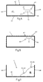
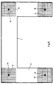
- the transmitter and receiver of the rangefinder (6) are on the end of the housing facing the ejection direction (6A) arranged. From the rangefinder (6) outgoing locating beams (OS) meet adjacent to emerging material flow (13) on the loading container (4) (see Figs. 5, 6 and 8, 9). In addition, the Location beams (OS1, OS2) slightly divergent from the Tangential ejection direction from the ejection flap (5) ejected material flow (13) away. The one from that Rangefinder (6) emitted location beams (OS) preferably hit in several around the impact area of the on the loading container (4) impinging material flow (13) around distributed relatively small scanning areas. In 5 and 6 are four rectangularly arranged Scanning areas (A1, A2, A3, A4) are shown. However, it is also provided that the location beams (OS) one on partly the material flow (13) hitting the loading container (4) or form a completely enclosing scanning surface (A) (cf. 8 and 9).
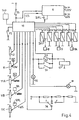
- the horizontal swivel of the discharge spout (3) is on the slewing ring (7) a motor (8), preferably a Hydraulic motor, arranged via two control valves (SV1, SV2), one for the right turn and one for the rotation to the left can be controlled.
- These control valves (SV1, SV2) are from the evaluation and control device (10) electrically depending on the distance signals (ES) and a control program (see FIG. 4).
- the hydraulic cylinder provided on the discharge flap (5) (9) for vertical pivoting of the same is over two Tilt control valves (SV3, SV4), one for the Panning up and one for panning to below, driven.
- the tilt control valves (SV3, SV4) are in turn from the evaluation and control device (10) corresponding to those received by the rangefinder (6) Distance signals (ES) can be controlled electrically (see Fig. 4).
- the valves (SV1, SV2; SV3, SV4) are preferably from Solenoid valves formed. Possibly. are two more valves (SV5, SV6) to control another hydraulic cylinder (9A) provided that the discharge spout (3) opposite the Swivel head (7) swiveled.
- the associated one Ejection flap angle (WAK) is controlled by a potentiometer (11A) signals the control device (10).
- a position indicator which is preferably designed as a potentiometer, is also located on the discharge chute (3) (11) for reporting the respective slewing ring swivel angle signal (DW) to the evaluation and control device (10).
- This position indicator (11) is preferably one Potentiometer formed with the horizontal swivel the discharge spout (3) is adjusted.
- On the harvester (1) is one in each of the two swivel angle end positions Limit switch (S2, S3) provided, its respective Switching states (open, closed) of the evaluation and control device (10) are supplied (see FIG. 1 and FIG. 4). This is a standardization of the slewing ring swivel angle signal (DW) and an immediate focus on the preferred positions easy to control.
- the device has a manually operated one Position selection switch (S4) with three switch positions on, preferably in the driver's cab of the harvester (1) is arranged.
- the switch positions are for Override of the automatic setting of the evaluation and Control device (10) supplied depending on Switch position the control valves (SV1, SV2) for the Horizontal pivoting of the discharge spout (3) actuated.
- the chute (3) is pivoted into the park position, in the left position (l) of the switch (S4) Chute (3) in a position to the left of the direction of travel pivoted and in the right switch position (r) in a right position to the direction of travel (see. Fig. 4).
- FIG. 10 is a height scale with an empty loading wagon (4) shown in longitudinal section. Above the loading wagon (4) the downwardly inclined range finder (6).
- the horizontal swivel of the spout (3) above the loading wagon (4) or when moving the loading wagon (4) opposite the spout (3) with the Distance meter (6) measured signal curve is in the Figure 10A shown.
- There are those marked with Location beams (OS1, OS2) determine height differences in Dependence on the time (t), e.g. B. the pivoting time, shown.
- This waveform is in the evaluation and Control device (10) can be stored.
- the signal (ES1) corresponds to the locating beam (OS1) and the signal (ES2) to the locating beam (OS2). In this way it is Height difference between the top edges (4F) of the Loader walls (4A, 4B, 4C, 4D) and the loader floor (4E).
- the Evaluation and control device (10) the length of the Determine the loading container (4).
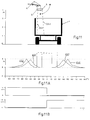
- Fig. 11 is a height scale with an empty loading wagon (4) shown in cross section. Above the loading wagon (4) is the discharge flap (5) with the Rangefinder (6) in the vertically downward inclined Position.
- Eject flap (5) with the rangefinder (6) from this position up to the horizontal position and back vertically to the starting position shown panned.
- the one with the locating rays (OS1, OS2) determined distance signals (ES1, ES2) versus the tilt swivel angle shown in Fig. 11A.
- These distance signals (ES1, ES2) can be used in Connection with the respective tilt swivel angles (lower Scale) by a coordinate transformation the width and determine the height of the loading container (4).
- the spout is preferred for cross-section measurement set transversely so that starting from simple Polar coordinates can be calculated.
- 11B are the predetermined control voltages on the tilt control valves (SV3, SV4) shown during pivoting.
- the loading volume of the loading container (4) from the evaluation and control device (10) can be determined.
- the cross-sectional and height dimensions via the evaluation and Control device (10) a maximum level, the leaves a sufficient loading area, determinable.
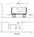
- Fig. 12 is a height scale with a partially filled Loader wagons (4) shown in longitudinal section. About that Loader wagon (4) is the rangefinder inclined downwards (6) arranged. The one with the locating rays (OS1, OS2) determined distance signals (ES1, ES2) are in 12A compared to the pivoting time (t). Of the The distance signal curve is a mirror image of the curve of the locally measured fill levels (h1, h2).
- Fig. 13 is a height scale with a partially filled Load container (4) shown in cross section.
- the down inclined discharge flap (5) with the rangefinder (6) is located above a side of the loading container wall.
- the with the location beams drawn in (OS1, OS2) determined distance signals (ES1, ES2) are compared to the Tilt pivot angle shown in Fig. 13A. This too Distance and angle signals are useful from the polar to Cartesian form.
- Fig. 13B are the respectively specified control voltages on the Tilt control valves (SV3, SV4) during pivoting shown. The crossing of the side by one The location beam is marked by an abruptly large one Distance measurement signals.
- the front view of the housing (6A) is one Embodiment of the range finder (6) shown.
- the end face is along three sides of the crop flow outlet several entrance and exit lenses (6E) arranged distributed, through which the locating rays (OS) emerge and those of Load container (4), the filling material (13) or the field floor reflected rays (RS) in the range finder (6) reach the recipient (s).
- OS locating rays
- RS field floor reflected rays
- Rangefinder (6) are located on the face of the Housing (6A) four rectangular transmitters (6B), here in the form of transmission lasers, each from an array of individual receivers (6C), here are surrounded in the form of photo receivers.
- a suitable one Phase control of the individual photo receivers is an optimal one Setting the reception directivity for receiving the reflected steel (RS) accessible.
- the four Location beams surround the good flow exit at all Pages.
- 16 is an embodiment of the range finder (6) with over the end face of the U-shaped housing (6A) evenly distributed piezo elements (6D) as Ultrasound transmitters and receivers shown.
- the embodiment of the Rangefinder (6) has arrays of individual Piezo elements (6D) that act as ultrasonic transmitters and recipients act.
- the distribution of the arrays is in each case all four sides of the flow of material.
- Fig. 18 is a partially loaded with filling (14) Loader wagons (4) shown. On the filling material (14) falls Location beam (OS) and forms a small scanning area there (A1). A bundle extends from this scanning area (A1) reflected rays pointing in different directions (RS) off. Part of the rays always become Rangefinder (6) reflects and reaches there the recipient (s) and becomes a Distance measurement used.
- OS Location beam
- a bundle extends from this scanning area (A1) reflected rays pointing in different directions (RS) off.
- RS reflected rays pointing in different directions
- a filling material (14) e.g. Silage is the surface not ideally smooth, but due to different Orientations of individual fibers or the like relatively uneven. This has the consequence that parallel locating beams (OS) be diffused. This is illustrated in Fig. 19, where the area of the scanning surface (A1) compared to FIG. 18 is shown enlarged. Even the minor ones Surface roughness of the container walls and the Soil are sufficient for always being a part of the at different angles onto the loading container (4) incident locating rays (OS) are reflected to the receiver becomes.
- a filling material (14) e.g. Silage is the surface not ideally smooth, but due to different Orientations of individual fibers or the like relatively uneven. This has the consequence that parallel locating beams (OS) be diffused. This is illustrated in Fig. 19, where the area of the scanning surface (A1) compared to FIG. 18 is shown enlarged. Even the minor ones Surface roughness of the container walls and the Soil are sufficient for always being a part of the at different angles onto
- the evaluation and control device (10) is actuated an optical or acoustic indicator (15) when the Loading container (4) is filled so far that nowhere the local fill level (h) more than the predeterminable maximum fill level.
- Via a control lamp (16) is displayed to the driver when the automatic Swivel control is switched on.
- Another one optical or acoustic display (17) is the driver communicated that the spout (3) in a Swivel angle end position or in the park position located. Whether the scanning area surrounding the crop flow (A) or at least one of the small scanning areas (A1 to A4) is located outside of the loading container (4)
- Control device (10) constantly monitored and possibly via a visual or acoustic warning device displayed.
- a potentiometer position indicator 11, 11A to 11B
- the given discharge flap angles (WAK) the discharge flap (5), the manifold height angle (WKH) and that Turntable swivel angle signal (DW) in electrical voltages converted, evaluated by the control device (10) become.
- WAK discharge flap angles
- WKH manifold height angle
- DW Turntable swivel angle signal
- FIG. 21A to 21C show views of the manifold (3) with the controllable flap (5) and the rangefinder (6) in scanner version.
- the respective scanner swivel angle (WS) is determined by the Scanner potentiometer (11C) of the control device (10) signals; Fig. 4.
- the manifold height which is generally unique Is adapted to the circumstances, with the Hydraulic actuator (9A), Fig. 20, by electromagnetic Control valves (SV5, SV6), Fig. 4, where the Manifold height angle (WKH) to the control device (10) from preferably as Potentiometer trained position indicator (11B) is reported back.
- the Laser scanning device SML, LS
- a Rangefinder (6) enables the laser sorters (LS, LS ') within a certain scanner angle (WS) to move.
- the location of the scanner device can be both on the movable flap part (5) of the manifold (3) and also be on the manifold (3) itself, as shown.
- this device works with the laser scanner so that the impact area of the crop beam (13, 13 ') always approximately in the longitudinal axis in the Load container cross-section center, as Fig. 22 shows.
- At the loading containers (4) can be of a standard width of Go out 2.50 m, or it is determined as described above. If the sensor beam (LOS) locates the upper edge (OK) of the Chopper (1) facing away from the side wall (BW), is from the in At this moment there are three angles (WS, DW, WKH) Distance (D) from the discharge flap (5) to the remote one Side wall (BW) calculated.
- the device works with the laser scanner so that a continuous adjustment of the Ejection flap (5) depending on the top edge scanner angle (WSO ', WSO '') when determining the upper edge (OK) of the remote Side dropside (BW) is done. Clarify this procedure 23 and 23A.
- the upper edge scanner angle (WSO ', WSO' ') when detecting the upper edge (OK) the side wall (BW) determined.
- the size of the respective top edge scanner angle (WSO ', WSO' ') becomes the Ejection flap (5) withdrawn more or less; at a small upper edge scanner angle (WSO '') around the flap (5) withdrawn a larger flap retraction angle (KWS ''); at a large upper edge scanner angle (WSO '), i.e.
- Range finder (6) here in an embodiment with a Scanners are used for the first procedure per scan pan each the side drop side (D) to the discharge flap (5) and the fill level (h) is determined.
- the second method is only the top edge scanner angle (WSO ', WSO' ') at all times Detection of the side wall edge (OK) determined. Need for this only marginal changes in the swivel angle of the Swivel device (SML) to be specified so that the Laser location beams (LOS) oscillate around the top edge (OK) and only full from time to time for level measurement swing through.
- the control of the associated Flap retraction angle (KWS ', KWS' ') is generated directly from the each at the top edge (OK) of the top edge scanner angle (WSO ', WSO' ').
- WSO ', WSO' ' The control of the associated Flap retraction angle (KWS ', KWS' ') is generated directly from the each at the top edge (OK) of the top edge scanner angle (WSO ', WSO' ').
- Container sizes such as width, side wall height, appropriate Include if different types of containers are used come.
- the scanner location beams (LOS, LOS ') the front and Brush the rear side of the ejector across the surface, sufficient only two laser emitters, whereas a fixed one Arrangement of the distance sensors on the discharge flap at least three pieces are necessary to exceed to prevent the side walls (BW) with the cargo flow; However, four distance sensors are expediently provided.
- a fixed locating beam is also sufficient one side of the crop jet and a pivoting one on the other side.
- the fixed locating beam only has the task of bringing the crop beam closer to one of the Report end walls of the loading container.
- a single scanner beam in two Directions for example in a narrow ellipse or Lissajo figure, preferably approximately U-shaped, distracted the area in the direction of travel in front of and behind the Good jet and the side wall edge to the side of the loading point goes through.
- the deflection amplitude in the Direction of travel much smaller than the lateral amplitude chosen and the frequency of the longitudinal deflection is half as large the transverse deflection frequency selected.
Landscapes
- Life Sciences & Earth Sciences (AREA)
- Environmental Sciences (AREA)
- Engineering & Computer Science (AREA)
- Mechanical Engineering (AREA)
- Filling Or Emptying Of Bunkers, Hoppers, And Tanks (AREA)
- Measurement Of Levels Of Liquids Or Fluent Solid Materials (AREA)
Description
- Fig. 1
- eine Draufsicht auf eine Erntemaschine mit einem Auswurfkrümmer und daran an einer Auswurfklappe angeordnetem Entfernungsmesser, welcher über einem Ladewagen positioniert ist,
- Fig. 2
- eine Seitenansicht des auf einem Drehkranz gelagerten Auswurfkrümmers in waagerechter Stellung der Auswurfklappe,
- Fig. 3
- eine Seitenansicht des Auswurfkrümmers in einer um fast 90° vertikal nach unten geneigten Stellung der Auswurfklappe,
- Fig. 4
- ein Blockschaltbild mit einer elektronischen Auswerte- und Steuereinrichtung, Steuerventilen, Schaltern und Kontrollampen,
- Fig. 5
- eine Draufsicht auf den Ladebehälter eines Ladewagens mit auftreffendem Gutstrom und vier um diesen angeordneten Abtastpunkten des Entfernungsmessers,
- Fig. 6
- eine Draufsicht auf den Ladebehälter mit teilweise neben dem Ladebehälter liegenden Abtastpunkten des Entfernungsmesser,
- Fig. 7
- einen senkrechten Schnitt durch einen teilweise gefüllten Ladebehälter mit zwei, unterschiedliche Füllhöhen signalisierenden, Abtastpunkten des Entfernungsmessers,
- Fig. 8
- eine Draufsicht auf den Ladebehälter mit einer den auftreffenden Gutstrom umschließenden Abtastfläche des Entfernungsmesser,
- Fig. 9
- eine Draufsicht auf den Ladebehälter wie in Fig. 8, jedoch mit einer teilweise außerhalb des Ladebehälters liegenden Abtastfläche,
- Fig. 10
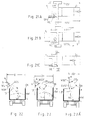
- eine Höhenskala und einen Längsschnitt durch einen Ladewagen mit darüber angeordnetem Entfernungsmesser,
- Fig. 10A
- die Signalverläufe der mit den Ortungsstrahlen über den Entfernungsmesser gemessenen Entfernungen längs eines leeren Ladewagens,
- Fig. 11
- eine Höhenskala und einen Querschnitt durch einen leeren Ladewagen mit darüber angeordneter Auswurfklappe mit dem Entfernungsmesser in der vertikal um 90° nach unten geneigten Stellung,
- Fig. 11A
- Signalverläufe am Entfernungsmesser bei der Vertikalverschwenkung der Auswurfklappe mit dem Entfernungsmesser,
- Fig. 11B
- den Steuerspannungsverlauf an den Neigungssteuerventilen für die Vertikalverschwenkung der Auswurfklappe,
- Fig. 12
- eine Höhenskala und einen Längsschnitt durch einen teilweise gefüllten Ladewagen mit darüber angeordnetem Entfernungsmesser,
- Fig. 12A
- Signalverläufe am Entfernungsmesser bei der Verschwenkung längs des teilweise gefüllten Ladebehälters,
- Fig. 13
- eine Höhenskala und einen Querschnitt durch einen teilweise gefüllten Ladewagen mit darüber angeordneter Auswurfklappe mit dem Entfernungsmesser in der vertikal um 90° nach unten geneigten Stellung,
- Fig. 13A
- Signalverläufe am Entfernungsmesser bei der Vertikalverschwenkung der Auswurfklappe über dem teilweise gefüllten Ladewagen,
- Fig. 13B
- den Steuerspannungsverlauf an den Neigungs-Steuerventilen während der Verschwenkung,
- Fig. 14 bis 17
- Stirnansichten verschiedener Ausführungsformen des Entfernungsmessers,
- Fig. 18
- einen Querschnitt durch einen teilweise gefüllten Ladewagen mit einem auf das Füllgut auftreffenden Ortungsstrahl und den davon ausgehendem Bündel reflektierter Strahlen,
- Fig. 19
- einen vergrößerten Ausschnitt des Abtastbereiches des Ortungsstrahles (vgl. Fig. 18) mit einfallenden Ortungsstrahlen und den reflektierten Strahlen,
- Fig. 20
- eine Laserscanneranordnung an einem Auswurfkrümmer in Seitenansicht,
- Fig. 21A bis 21C
- Aufsichten auf die Laserscanneranordnung in verschiedenen Scanner-Schwenkzuständen,
- Fig. 22
- einen Ladebehälter im Querschnitt bei einem ersten Ladesteuerverfahren mit Lasercanner,
- Fig. 23 und 23A
- einen Ladebehälterquerschnitt bei einem zweiten Ladesteuerverfahren in zwei Zuordnungen zum Auswurfort mit Laserscanner.
- Auswurfklappenwinkel (WAK) der Auswurfklappe (5), (Fig. 20),
- der Krümmerhöhe, die durch Krümmerhöhenwinkel (WKH) bestimmt ist,
- der Auswurfrichtung, d.h. dem Drehkranzschwenkwinkelsignal (DW), Fig. 1.
Claims (17)
- Vorrichtung zur automatischen Befüllung von einem fahrbaren Ladebehälter (4) mit einem Gutstrom (13), welche einen/ein um eine vertikale und horizontale Achse oder eine vertikale Achse von einer Auswerk- und Steuereinrichtung (10) gesteuert verschwenkbaren/verschwenkbares Auswurfkrümmer/Auswurfrohr (3, 5), gegebenenfalls mit einer endseitigen, schwenkbaren Auswurfklappe (5), aufweist, wobei der Auswurfkrümmer bzw. das Auswurfrohr (3, 5) mit mindestens einem vertikal und/oder horizontal verschwenkbaren Entfernungmesser (6) ausgestattet ist, der die Füllstandshöhe h des Gutes im fahrbaren Ladebehälter (4) relativ zur maximal möglichen Füllstandshöhe im fahrbaren Ladebehälter (4) erfaßt, und der verschwenkbare Entfernungsmesser (6) im auswurfseitigen Endbereich des Auswurfkrümmers/Auswurfrohrs (3, 5) angeordnet ist,
dadurch gekennzeichnet,
daß der Entfernungsmesser (6) aus einem optischen und/oder akustischen Entfernungsmesser (6) besteht, der Entfernungssignale (ES) erzeugt, die von diesem Entfernungsmesser (6) erzeugten Entfernungssignale (ES) einer elektronischen Auswerte- und Steuereinrichtung (10) zugeführt sind, welche aus den Entfernungssignalen (ES) mittels eines Steuerprogramms die jeweilige Füllstandshöhe (h) und die Lage der Kanten der Seitenwände des Ladebehälters (4) erfaßt und die Entfernungssignale (ES) laufend zu elektrischen Stellsignalen auswertet, die an Steuerventile (SV1-SV6) zu deren Betätigung übermittelt sind, und wobei das Steuerprogramm die Stellsignale unter Auswertung der zugeführten Entfernungssignale (ES) so bestimmt, daß die Auswurfrichtung des Gutstromes (13) innerhalb der Lage der Kanten des Ladebehälters (4) liegt. - Vorrichtung nach Anspruch 1, dadurch gekennzeichnet, daß der Entfernungsmesser (6) von einer LASER-Interferometer-Meßvorrichtung mit einem oder mehreren Sendern (6B) in Form von Sendelasern und Empfängern (6C) in Form von Photoempfängern gebildet ist, wobei die von dem Sendelaser ausgehenden Ortungsstrahlen (OS, LOS, LOS') vom Ladebehälter (4), dem Füllgut (14) und/oder dem Feldboden zumindest teilweise zu den Photoempfängern reflektiert werden, oder daß der Entfernungsmesser (6) von einer Ultraschall-Meßvorrichtung mit einem oder mehreren Ultraschall-Sendern und -Empfängern (6D), wie Piezoelementen, gebildet ist, wobei die von den Ultraschall-Sendern ausgehenden Ortungsstrahlen (OS) vom Ladebehälter (4), dem Füllgut (14) und/oder dem Feldboden zumindest teilweise zu den Empfängern reflektiert werden.
- Vorrichtung nach einem der vorstehenden Ansprüche, dadurch gekennzeichnet, daß von dem Entfernungsmesser (6) ausgehende Ortungsstrahlen (OS) benachbart zum austretenden Gutstrom (13) auf den Ladebehältern (4) auftreffen.
- Vorrichtung nach einem der Ansprüche 2 oder 3, dadurch gekennzeichnet, daß die von dem Entfernungsmesser (6) ausgehenden Ortungsstrahlen (OS) eine den auf den Ladebehälter (4) auftreffenden Gutstrom (13) teilweise oder vollständig umschließende Abtastfläche (A) beaufschlagen oder daß die von dem Entfernungsmesser (6) ausgehenden Ortungsstrahlen (OS) mehrere um die Fläche des auf dem Ladebehälter (4) auftreffenden Gutstromes (13) herum verteilt angeordnete eng begrenzte Abtastflächen (A1, A2, A3, A4) beaufschlagen oder der Entfernungsmesser (6) je einen Ortungsstrahl (LOS, LOS') zu beiden Seiten parallel zum Gutstrom (13), gesteuert verschwenkbar abgibt und aufnimmt.
- Vorrichtung nach einem der vorstehenden Ansprüche, dadurch gekennzeichnet, daß der an einer Erntemaschine (1) angeordnete Auswurfkrümmer/Auswurfrohr (3) auf einem Drehkranz (7) in einem Schwenkwinkelbereich von etwa 240° zwischen zwei jeweils quer zur Erntemaschinen-Längsrichtung angeordneten Schwenkwinkel-Endlagen horizontal schwenkbar gelagert ist, und der Drehkranz (7) von einem über die Auswerte- und Steuereinrichtung (10) ansteuerbaren Motor (8) zur Horizontalverschwenkung des Auswurfkrümmers/Auswurfrohres (3) angetrieben wird.
- Vorrichtung nach Anspruch 5, dadurch gekennzeichnet, daß an dem Auswurfkrümmer/Auswurfrohr (3) ein erster Positionsmelder (11) angeordnet ist, der eine jeweilige Horizontal-Schwenkstellung an die Auswerte- und Steuereinrichtung (10) meldet und daß an der Erntemaschine (1) in den Schwenkwinkel-Endlagen des Auswurfkrümmers/Auswurfrohres (3) je ein Endschalter (S2, S3) vorgesehen ist, deren jeweiliger Schaltzustand (Auf, Zu) der Auswerte- und Steuereinrichtung (10) zugeführt ist.
- Vorrichtung nach Anspruch 5, dadurch gekennzeichnet, daß der Motor (8) zum Verschwenken des Auswurfkrümmers/Auswurfrohres (3) von einem über zwei Steuerventile (SV1, SV2), eines für eine Drehung nach links und eines für eine Drehung nach rechts, ansteuerbaren Hydraulikmotor gebildet ist, wobei die Steuerventile (SV1, SV2) jeweils von der Auswerte- und Steuereinrichtung (10) elektrisch angesteuert werden.
- Vorrichtung nach einem der vorstehenden Ansprüche, dadurch gekennzeichnet, daß der Entfernungsmesser (6) an der endseitig am Auswurfkrümmer/Auswurfrohr (3) vertikal schwenkbar gelagerten Auswurfklappe (5) angeordnet ist, und die Auswurfklappe (5) mittels eines am Auswurfkrümmer/Auswurfrohr (3) angelenkten Hydraulikzylinders (9) in einem Schwenkwinkelbereich von etwa 90° verschwenkbar ist, wobei der Hydraulikzylinder (9) von zwei Neigungssteuerventilen (SV3, SV4), eines für die Verschwenkung nach oben und eines für die Verschwenkung nach unten, angesteuert wird, welche ihrerseits von der Auswerte- und Steuereinrichtung (10) elektrisch angesteuert sind.
- Vorrichtung nach Anspruch 8, dadurch gekennzeichnet, daß an der vertikal schwenkbaren Auswurfklappe (5) ein zweiter Positionsmelder (11A) angeordnet ist, der deren Neigestellung an die Auswerte- und Steuereinheit (10) signalisiert.
- Vorrichtung nach Anspruch 8, dadurch gekennzeichnet, daß die Auswurfklappe (5) zwischen einer etwa waagerechten und einer etwa vertikal nach unten gerichteten Stellung verschwenkbar ist.
- Vorrichtung nach einem der vorstehenden Ansprüche, dadurch gekennzeichnet, daß der Entfernungsmesser (6) in einem an der nach unten offenen Auswurfklappe (5) und diese von oben übergreifenden U-förmigen Gehäuse (6A) angeordnet ist, wobei die Sender (6B, 6D) und die Empfänger (6C, 6D) des Entfernungsmessers (6) an der der Auswurfrichtung zugewandten Stirnseite des Gehäuses (6A) angeordnet sind.
- Vorrichtung nach einem der vorstehenden Ansprüche, dadurch gekennzeichnet, daß die Auswerte- und Steuereinrichtung (10) jeweils in einem leeren Ladebehälter (4) den Abstand zwischen einer vorderen und einer hinteren Ladebehälter-Wand (4A, 4B), den Abstand zwischen den seitlichen Ladebehälterwänden (4C, 4D) und den Abstand von den oberen Rändern (4F) der Ladebehälter-Wände (4A, 4B, 4C, 4D) zum Boden (4E) des Ladebehälters (4) durch Horizontal- und Vertikalverschwenkungen des Entfernungsmessers (6) sowie Koordinatentransformation vermißt und daraus ein Ladevolumen und/oder eine maximale Füllstandshöhe ermittelt und speichert.
- Vorrichtung nach einem der vorstehenden Ansprüche, dadurch gekennzeichnet, daß die Auswerte- und Steuereinrichtung (10) in einem Ladebetrieb laufend die Entfernungssignale (ES) bezüglich des Erreichens einer vorgegebenen oder vorher bestimmten maximalen Füllstandshöhe in einem jeweiligen Abtastbereich überwacht und dann, wenn diese erreicht ist, eine solche Verschwenkung des Auswurfkrümmers/Auswurfrohres (3) und/oder der Auswurfklappe (5) systematisch fortschreitend steuert, bis die Entfernungssignale (ES) signalisieren, daß der Gutstrom (13) an einer Stelle des Ladebehälters (4) mit einer geringeren Füllstandshöhe (h) auftrifft.
- Vorrichtung nach Anspruch 13, dadurch gekennzeichnet, daß die Auswerte- und Steuereinrichtung (10) eine akustische oder optische Warnvorrichtung betätigt, wenn die Auswertung der Entfernungssignale (ES) ergibt, daß die Abtastfläche (A) oder mindestens eine der Abtastflächen (A1, A2, A3, A4) des Entfernungsmessers (6) außerhalb des Ladebehälters (4) liegt.
- Vorrichtung nach einem der Ansprüche 1 bis 12, dadurch gekennzeichnet, daß die Auswerte- und Steuervorrichtung (10) durch eine Verschwenkvorrichtung (SML) des Entfernungsmessers (6) dessen Ortungsstrahl(en) (LOS, LOS') unabhängig von der Schwenkstellung der Auswurfklappe (5) laufend scannend in Flächen, die in Fahrtrichtung nahe vor und hinter dem Gutstrom (13) liegen, verschwenkt und einen Seitenabstand (D) einer Oberkante (OK) einer entferntliegenden Behälterseitenwand (BW) und eine Füllstandshöhe (h) aus den Entfernungssignalen (ES) und einen Scannerschwenkwinkel (WS) und dem Drehkranz-Schwenkwinkelsignal (DW) sowie der Position des Entfernungsmessers (6) an der Erntemaschine (1) durch eine Koordinatentransformation einen Auswurfklappenwinkel (WAK) derart berechnet und ausgebend ansteuert, daß der zentrale Auftreffort des Gutstromes (13) jeweils in der Querschnittsmitte des Ladebehälters (4) bei der jeweiligen Füllstandshöhe (h) liegt, und die Steuervorrichtung (10) jeweils das Erreichen einer maximalen Füllstandshöhe überprüft und ggf. eine fortschreitende Verschwenkung des Drehkanzes (7) ansteuert.
- Vorrichtung nach einem der Ansprüche 1 bis 12, dadurch gekennzeichnet, daß die Auswerte- und Steuervorrichtung (10) durch eine Verschwenkvorrichtung (SML) des Entfernungsmessers (6) dessen Ortungsstrahl(en) (LOS, LOS') unabhängig von der Schwenkstellung der Auswurfklappe (5) scannend in Flächen, die in der Fahrtrichtung nahe vor und hinter dem Gutstrom (13) verlaufen, verschwenkt und laufend eine Oberkante (OK) einer entferntliegenden Behälterseitenwand (BW) aus den Entfernungssignalen (ES) ertastet und den dazugehörigen Oberkanten-Scannerwinkel (WSO', WSO'') gegen die Senkrechte ermittelt und daraus einen Klappenrückzugswinkel (KWS', KWS'') gegenläufiger Größe bestimmt, um den sie die Auswurfklappe (5) gegenüber dem Ortungsstrahl (LOS, LOS') nach unten gerichtet steuernd einstellt, so daß bei einem relativ großen gemessenen Scannerschwenkwinkel (WSO') der Gutstrahl (13') etwa auf den unteren Bereich der entfernten Behälterseitenwand (BW) gerichtet ist und bei einem relativ kleinen gemessenen Scannerschwenkwinkel (WSO'') der Gutstrahl (13'') etwa auf die Querschnittsmitte des Behälterbodens gerichtet ist, und mit dem periodisch verschwenkten Ortungsstrahl (LOS, LOS') die Füllstandshöhe (h) jeweils auf das Erreichen einer maximalen Füllstandshöhe überprüft und ggf. eine fortschreitende Verschwenkung des Drehkranzes (7) ansteuert.
- Vorrichtung nach einem der vorstehenden Ansprüche, dadurch gekennzeichnet, daß die Auswerte- und Steuereinrichtung (10) eine akustische und/oder optische Anzeige (15) betätigt, wenn der Ladebehälter (4) bereits so weit mit dem Füllgut (14) beladen ist, daß an keiner Stelle des Ladebehälters (4) die lokale Füllstandshöhe (h) unter der maximalen Füllstandshöhe liegt.
Applications Claiming Priority (2)
| Application Number | Priority Date | Filing Date | Title |
|---|---|---|---|
| DE4403893A DE4403893A1 (de) | 1994-02-08 | 1994-02-08 | Vorrichtung zur automatischen Befüllung von Ladebehältern mit einem Gutstrom |
| DE4403893 | 1994-02-08 |
Publications (2)
| Publication Number | Publication Date |
|---|---|
| EP0666018A1 EP0666018A1 (de) | 1995-08-09 |
| EP0666018B1 true EP0666018B1 (de) | 1999-08-11 |
Family
ID=6509757
Family Applications (1)
| Application Number | Title | Priority Date | Filing Date |
|---|---|---|---|
| EP95100930A Expired - Lifetime EP0666018B1 (de) | 1994-02-08 | 1995-01-25 | Vorrichtung zur automatischen Befüllung von Ladebehältern |
Country Status (3)
| Country | Link |
|---|---|
| US (1) | US5575316A (de) |
| EP (1) | EP0666018B1 (de) |
| DE (2) | DE4403893A1 (de) |
Families Citing this family (128)
| Publication number | Priority date | Publication date | Assignee | Title |
|---|---|---|---|---|
| DE19531662A1 (de) * | 1995-08-29 | 1997-03-06 | Claas Ohg | Vorrichtung zum automatischen Befüllen von Ladebehältern |
| DE19647522A1 (de) * | 1996-11-16 | 1998-05-20 | Claas Ohg | Vorrichtung zur Überwachung der Überladung von Gütern von einer Arbeitsmaschine auf ein Transportfahrzeug |
| DE29700426U1 (de) * | 1997-01-11 | 1997-05-15 | Claas KGaA, 33428 Harsewinkel | Selbstfahrender Feldhäcksler mit am Ende seines Auswurfrohres angeordneter verschwenkbarer Klappe |
| DE19703074B4 (de) * | 1997-01-29 | 2005-04-14 | Reinhard Ebert | Erntemaschinen mit Überwachungseinrichtung des Erntegutentladevorganges |
| DE19717661A1 (de) * | 1997-04-25 | 1998-10-29 | Krupp Foerdertechnik Gmbh | Verfahren und Einrichtung zur kontinuierlichen Erkennung wesentlicher Merkmale eines Schienenfahrzeugs |
| DE19717662A1 (de) * | 1997-04-25 | 1998-10-29 | Krupp Foerdertechnik Gmbh | Verfahren und Einrichtung zur kontinuierlichen Ermittlung der Position eines Schienenfahrzeugs |
| DE19756875A1 (de) | 1997-12-19 | 1999-07-01 | Siemens Ag | Verladeanlage zum Beladen eines Transportmittels mit Schüttgut |
| US6186730B1 (en) | 1998-01-12 | 2001-02-13 | Justin Place | Apparatus and method for loading agricultural material |
| US6012272A (en) * | 1998-03-18 | 2000-01-11 | Dillon; Ben N. | Articulated combine |
| DE19848127A1 (de) | 1998-10-19 | 2000-04-20 | Claas Selbstfahr Erntemasch | Vorrichtung zur Steuerung einer Überladeeinrichtung |
| US6216071B1 (en) | 1998-12-16 | 2001-04-10 | Caterpillar Inc. | Apparatus and method for monitoring and coordinating the harvesting and transporting operations of an agricultural crop by multiple agricultural machines on a field |
| US6454496B1 (en) | 1999-09-30 | 2002-09-24 | Berry Plastics Design Corporation | System for loading and unloading polystyrene pellets into and from a trailer |
| DE19947739A1 (de) * | 1999-10-05 | 2001-04-12 | Froelich Karin | Verfahren und Vorrichtung zum Verladen von Schüttgütern in verfahrbare Behälter |
| DE19949325C1 (de) * | 1999-10-13 | 2001-04-19 | Case Harvesting Sys Gmbh | Schwenkeinrichtung für den Auswurfbogen von Feldhäckslern |
| US6296435B1 (en) * | 2000-02-09 | 2001-10-02 | J. & M. Manufacturing Co., Inc. | Grain wagon having an unloading conveyor with a moveable discharge spout controlled from a tow vehicle |
| US6497546B2 (en) | 2000-02-09 | 2002-12-24 | J. & M. Manufacturing Co., Inc. | Grain wagon having an unloading conveyor with a moveable discharge spout controlled from a tow vehicle |
| DE10021664B4 (de) † | 2000-05-04 | 2004-05-06 | Maschinenfabrik Bernard Krone Gmbh | Erntemaschine, insbesondere selbstfahrender Feldhäcksler |
| DE10064861A1 (de) * | 2000-12-23 | 2002-06-27 | Claas Selbstfahr Erntemasch | Vorrichtung und Verfahren zur automatischen Steuerung einer Überladeeinrichtung an landwirtschaftlichen Erntemaschinen |
| US6682416B2 (en) * | 2000-12-23 | 2004-01-27 | Claas Selbstfahrende Erntemaschinen Gmbh | Automatic adjustment of a transfer device on an agricultural harvesting machine |
| US20020084174A1 (en) * | 2000-12-29 | 2002-07-04 | Maurice Minardi | Soft drop preform conveyor system |
| US6754584B2 (en) * | 2001-02-28 | 2004-06-22 | Enpoint, Llc | Attitude measurement using a single GPS receiver with two closely-spaced antennas |
| FI111836B (fi) * | 2001-04-17 | 2003-09-30 | Sandvik Tamrock Oy | Menetelmä ja laitteisto dumpperin automaattiseksi kuormaamiseksi |
| DE10119279A1 (de) * | 2001-04-20 | 2002-10-24 | Deere & Co | Einrichtung zur Steuerung der Position einer Austrageinrichtung einer landwirtschaftlichen Erntemaschine |
| DE20110378U1 (de) | 2001-06-22 | 2002-01-24 | Listenow GmbH & Co., 71277 Rutesheim | Einrichtung zum Positionieren eines Silobehälters |
| DE10134137B4 (de) * | 2001-07-13 | 2006-02-23 | Maschinenfabrik Bernard Krone Gmbh | Selbstfahrende landwirtschaftliche Erntemaschine |
| DE10141702A1 (de) * | 2001-08-25 | 2003-03-06 | Deere & Co | Einrichtung zum Antrieb einer Austrageinrichtung einer landwirtschaftlichen Erntemaschine |
| US6943824B2 (en) † | 2002-03-13 | 2005-09-13 | Deere & Company | Image processing spout control system |
| DE10240219A1 (de) * | 2002-08-28 | 2004-03-11 | Claas Selbstfahrende Erntemaschinen Gmbh | Vorrichtung zur Steuerung einer Überladeeinrichtung |
| DE10242164A1 (de) * | 2002-09-10 | 2004-04-01 | Claas Selbstfahrende Erntemaschinen Gmbh | Verfahren zur Steuerung einer Überladeeinrichtung |
| US20050028508A1 (en) * | 2002-11-26 | 2005-02-10 | Roderick Komar | Picking accessory for berry harvester |
| DE10309700B4 (de) | 2003-03-06 | 2012-07-12 | Deere & Company | Austrageinrichtung einer landwirtschaftlichen Erntemaschine |
| US6805232B1 (en) | 2003-06-12 | 2004-10-19 | Ralph Isom | Apparatus and method for directing and cushioning items during piling |
| US7454290B2 (en) * | 2003-09-18 | 2008-11-18 | The Board Of Trustees Of The Leland Stanford Junior University | GPS/INS vehicle attitude system |
| DE10348090A1 (de) † | 2003-10-16 | 2005-05-19 | Deere & Company, Moline | Landwirtschaftliche Arbeitsmaschine |
| DE102004020127A1 (de) | 2004-04-24 | 2005-11-24 | Deere & Company, Moline | Erntemaschine mit einer Austrageinrichtung |
| DE102004031894A1 (de) * | 2004-06-30 | 2006-01-19 | Hauni Primary Gmbh | Befüllung eines Zwischenspeichers mit Tabakgut |
| DE102004052298A1 (de) * | 2004-10-06 | 2006-06-08 | Claas Selbstfahrende Erntemaschinen Gmbh | Überladeassistenzsystem |
| US20060245863A1 (en) * | 2005-04-19 | 2006-11-02 | Paul Wilcott | Solid state detection system for measuring high levels in grain bins |
| DE102005059003A1 (de) * | 2005-12-08 | 2008-03-27 | Claas Selbstfahrende Erntemaschinen Gmbh | Routenplanungssystem für landwirtschaftliche Arbeitsmaschinen |
| US7430845B2 (en) * | 2005-12-14 | 2008-10-07 | Deere & Company | Harvesting machine with a measuring device for capturing the throughput of collected crop material |
| US7994796B2 (en) * | 2006-03-01 | 2011-08-09 | Vega Grieshaber Kg | Circuit arrangement and method for monitoring the function of a vibration level switch and/or a fill level measuring apparautus |
| DE102007009666A1 (de) * | 2007-02-22 | 2008-08-28 | Carl Zeiss Microimaging Gmbh | Anordnung zum Befüllen eines Behälters mit Schüttgut |
| DE102007016670A1 (de) * | 2007-04-04 | 2008-10-09 | Claas Selbstfahrende Erntemaschinen Gmbh | Selbstfahrende landwirtschaftliche Erntemaschine mit steuerbarer Überladeeinrichtung |
| US8260499B2 (en) * | 2007-05-01 | 2012-09-04 | Deere & Company | Automatic steering system and method for a work vehicle with feedback gain dependent on a sensed payload |
| EP2020174B1 (de) * | 2007-08-03 | 2012-02-29 | AGROCOM GmbH & Co. Agrarsystem KG | Landwirtschaftliche Arbeitsmaschine |
| US8286984B2 (en) * | 2007-12-18 | 2012-10-16 | Dillon Ben N | Articulated combine with unloading and rear bogey steering architecture |
| DE102008008260B4 (de) | 2008-02-08 | 2010-09-09 | Wirtgen Gmbh | Steuerung einer Gewinnungsmaschine und Gewinnungsmaschine |
| DE102008002006A1 (de) | 2008-05-27 | 2009-12-03 | Deere & Company, Moline | Steueranordnung zur Kontrolle des Überladens landwirtschaftlichen Ernteguts von einer Erntemaschine auf ein Transportfahrzeug |
| US7671794B2 (en) * | 2008-06-02 | 2010-03-02 | Enpoint, Llc | Attitude estimation using intentional translation of a global navigation satellite system (GNSS) antenna |
| US7806757B2 (en) * | 2008-07-16 | 2010-10-05 | Deere & Company | Dual sided belted unloader |
| US8280595B2 (en) * | 2008-08-12 | 2012-10-02 | Cnh America Llc | System and method employing short range communications for communicating and exchanging operational and logistical status information among a plurality of agricultural machines |
| US8145393B2 (en) * | 2008-09-17 | 2012-03-27 | Cnh America Llc | System and method employing short range communications for interactively coordinating unloading operations between a harvester and a grain transport |
| US20100071333A1 (en) * | 2008-09-22 | 2010-03-25 | Temple Douglas G | Loading auger deflector |
| DE102008052437A1 (de) * | 2008-10-21 | 2010-04-29 | Siemens Aktiengesellschaft | Vorrichtung und Verfahren zur Detektion einer Substanz mit Hilfe eines Dünnfilmresonators mit Isolationsschicht |
| US7762290B2 (en) | 2008-11-06 | 2010-07-27 | Poet Research, Inc. | System for loading particulate matter into a transport container |
| US8126620B2 (en) * | 2009-04-28 | 2012-02-28 | Cnh America Llc | Grain transfer control system and method |
| US8077023B2 (en) * | 2009-05-08 | 2011-12-13 | Hal's Construction, Inc. | Operational signal system and signal light arrangement |
| US7877181B2 (en) * | 2009-05-11 | 2011-01-25 | Deere & Company | Scalable grain tank fill level display |
| US7874899B2 (en) * | 2009-05-18 | 2011-01-25 | Deere & Company | Unload rate control for an unloading system in an agricultural harvester |
| DE102009027245A1 (de) | 2009-06-26 | 2010-12-30 | Deere & Company, Moline | Steueranordnung zur Kontrolle des Überladens landwirtschaftlichen Ernteguts von einer Erntemaschine auf ein Transportfahrzeug |
| US8464508B2 (en) * | 2009-07-31 | 2013-06-18 | Agco Corporation | Biomass baler |
| US20110023440A1 (en) * | 2009-07-31 | 2011-02-03 | Agco Corporation | Method For Projecting Biomass From A Combine Harvester |
| US20110024538A1 (en) * | 2009-07-31 | 2011-02-03 | Agco Corporation | Combine Chopper For Feeding A Baler |
| US8443580B2 (en) * | 2009-07-31 | 2013-05-21 | Agco Corporation | Baler pickup for collecting biomass from a combine harvester |
| US20110023439A1 (en) * | 2009-07-31 | 2011-02-03 | Agco Corporation | Biomass Deflector |
| US8490375B2 (en) * | 2009-07-31 | 2013-07-23 | Agco Corporation | Baler collector for collecting biomass from a combine harvester |
| US20110029909A1 (en) * | 2009-07-31 | 2011-02-03 | Agco Corporation | User Interface With Biomass Deflection Information |
| PL2311307T3 (pl) * | 2009-09-07 | 2012-09-28 | Claas E Systems Gmbh | Wskaźnik stopnia napełnienia, pojazd rolniczy zawierający taki wskaźnik oraz sposób kontroli napełniania obszaru docelowego |
| US8197312B2 (en) * | 2009-12-04 | 2012-06-12 | Cnh America Llc | Extension for an agricultural combine unloader tube |
| US20110164952A1 (en) * | 2010-01-06 | 2011-07-07 | Hollenberg David H | Grain cart with directional discharge |
| BE1019192A3 (nl) | 2010-02-21 | 2012-04-03 | Cnh Belgium Nv | Werkwijze voor het richten van een ontlaadtoestel van een oogstmachine naar een container. |
| US8380401B2 (en) | 2010-06-09 | 2013-02-19 | Cnh America Llc | Automatic grain transfer control system based on real time modeling of a fill level profile for regions of the receiving container |
| DE102010038661B4 (de) | 2010-07-29 | 2020-07-02 | Deere & Company | Erntemaschine mit einem an einem Fluggerät befestigten Sensor |
| US8789563B2 (en) * | 2010-10-12 | 2014-07-29 | Deere & Company | Intelligent grain bag loader |
| DE102010043854B4 (de) | 2010-11-12 | 2016-01-14 | Deere & Company | Steueranordnung zur Kontrolle des Überladens landwirtschaftlichen Ernteguts von einer Erntemaschine auf ein Transportfahrzeug |
| US9002591B2 (en) | 2011-02-18 | 2015-04-07 | Cnh Industrial America Llc | Harvester spout control system and method |
| DE102011005400B4 (de) * | 2011-03-11 | 2015-05-28 | Deere & Company | Anordnung und Verfahren zur Abschätzung des Füllgrades beim Überladen landwirtschaftlichen Ernteguts von einer Erntemaschine auf ein Transportfahrzeug |
| DE102011002071A1 (de) * | 2011-04-15 | 2012-10-18 | Claas Selbstfahrende Erntemaschinen Gmbh | System und Verfahren zur Steuerung der Erntegutüberladung |
| DE102011050629A1 (de) * | 2011-05-25 | 2012-11-29 | Claas Selbstfahrende Erntemaschinen Gmbh | Erntevorrichtung |
| US20130019580A1 (en) * | 2011-07-20 | 2013-01-24 | Anderson Noel W | Bidirectional harvesting system |
| US9545048B2 (en) | 2011-08-15 | 2017-01-17 | Deere & Company | System for automated unloading of an agricultural material |
| DE102011114185A1 (de) | 2011-09-22 | 2013-03-28 | Bomag Gmbh | Arbeitszug mit einer Fräsvorrichtung und einer Transporteinrichtung mit einer Sensoreinrichtung zur Abstandsüberwachung, Fräsvorrichtung mit einer Sensoreinrichtung und Verfahren zur Abstandsüberwachung bei einem Arbeitszug |
| DE102011114183A1 (de) * | 2011-09-22 | 2013-03-28 | Bomag Gmbh | Verfahren zur Steuerung eines Beladungsvorgangs eines Transportfahrzeugs mit Fräsgut, Vorrichtung zur Durchführung eines solchen Verfahrens und Fräsvorrichtung |
| US8868304B2 (en) | 2012-02-10 | 2014-10-21 | Deere & Company | Method and stereo vision system for facilitating the unloading of agricultural material from a vehicle |
| US9392746B2 (en) | 2012-02-10 | 2016-07-19 | Deere & Company | Artificial intelligence for detecting and filling void areas of agricultural commodity containers |
| US9861040B2 (en) | 2012-02-10 | 2018-01-09 | Deere & Company | Method and stereo vision system for facilitating the unloading of agricultural material from a vehicle |
| US9113598B2 (en) * | 2012-03-20 | 2015-08-25 | J. & M. Manufacturing Co., Inc. | Grain cart having an inclined folding unloading auger conveyor with an askewed flow control spout |
| DE102012215005A1 (de) | 2012-08-23 | 2014-02-27 | Wirtgen Gmbh | Selbstfahrende Fräsmaschine, sowie Verfahren zum Lenken einer selbstfahrenden Fräsmaschine |
| DE102012215013A1 (de) | 2012-08-23 | 2014-02-27 | Wirtgen Gmbh | Selbstfahrende Fräsmaschine, sowie Verfahren zum Abladen von Fräsgut |
| US9061834B2 (en) | 2012-10-01 | 2015-06-23 | Dethmers Manufacturing Company | Manipulative auger system |
| US9326444B2 (en) | 2013-02-08 | 2016-05-03 | Deere & Company | Method and stereo vision system for facilitating the unloading of agricultural material from a vehicle |
| US9481281B2 (en) * | 2013-04-11 | 2016-11-01 | Dp Techlink, Llc | Transport assembly locking system |
| DE102014105643B4 (de) | 2013-04-22 | 2026-01-22 | Carnegie Mellon University | System und Verfahren zur Verbesserung der Robustheit eines automatisierten Entladesystems |
| CA2821182A1 (en) * | 2013-07-17 | 2015-01-17 | Sheldon Affleck | Method and apparatus for loading railcars with crop material |
| GB2517049B (en) | 2013-07-28 | 2019-09-11 | Deere & Co | Artificial intelligence for detecting and filling void areas of agricultural commodity containers |
| BE1021164B1 (nl) | 2013-10-28 | 2016-01-18 | Cnh Industrial Belgium Nv | Ontlaadsystemen |
| DE102013018724B4 (de) * | 2013-11-08 | 2015-09-03 | LASE Industrielle Lasertechnik GmbH | Landwirtschaftliche Erntemaschine |
| BE1021167B1 (nl) * | 2013-12-10 | 2016-01-14 | Cnh Industrial Belgium Nv | Sensoropstelling |
| BR102015013229B8 (pt) | 2014-06-13 | 2021-12-14 | Cnh Ind America Llc | Sistema de controle para um veículo agrícola e método para calibrar o alinhamento de uma saída do transportador de um veículo agrícola com um compartimento de armazenamento |
| BR102015013228B1 (pt) | 2014-06-13 | 2020-11-24 | Cnh Industrial America Llc | SISTEMA E METODO DE CONTROLE PARA UM VEfCULO AGRiCOLA |
| DE102014216603B4 (de) | 2014-08-21 | 2018-02-22 | Wirtgen Gmbh | Selbstfahrende Fräsmaschine, sowie Verfahren zum Abladen von Fräsgut |
| DE102014216763B4 (de) | 2014-08-22 | 2018-07-26 | Wirtgen Gmbh | Selbstfahrende Fräsmaschine, sowie Verfahren zum Abladen von Fräsgut |
| DE102014216713B4 (de) | 2014-08-22 | 2018-09-06 | Wirtgen Gmbh | Selbstfahrende Fräsmaschine, sowie Verfahren zum Abladen von Fräsgut |
| BE1022649B1 (nl) * | 2015-04-02 | 2016-06-24 | Cnh Industrial Belgium Nv | Verbeteringen in of m.b.t. gewasuitlopen. |
| DE102015108055A1 (de) * | 2015-05-21 | 2016-11-24 | Claas Saulgau Gmbh | Verfahren und Steuerungseinrichtung zum Betreiben eines landwirtschaftlichen Ladewagens |
| DE102016108902A1 (de) * | 2016-05-13 | 2017-11-16 | Claas Saulgau Gmbh | Verfahren und Steuerungseinrichtung zum Betreiben eines landwirtschaftlichen Transportwagens sowie Transportwagen |
| US10159191B2 (en) * | 2016-09-23 | 2018-12-25 | Deere & Company | Harvester grain unloader |
| DE102016222589B4 (de) | 2016-11-16 | 2020-01-16 | Wirtgen Gmbh | Selbstfahrende Fräsmaschine, sowie Verfahren zum Steuern einer selbstfahrenden Fräsmaschine |
| DE102017220148A1 (de) * | 2017-11-13 | 2019-05-16 | Deere & Company | Austrageinrichtung für einen Feldhäcksler |
| DE102017220869A1 (de) | 2017-11-22 | 2019-05-23 | Wirtgen Gmbh | Selbstfahrende Fräsmaschine, Verfahren zum automatischen Beladen eines Transportmittels mit Fräsgut, sowie Straßen- oder Bodenbearbeitungseinheit |
| DE102019104218A1 (de) | 2019-02-19 | 2020-08-20 | Wirtgen Gmbh | Arbeitszug, umfassend eine Bodenbearbeitungsmaschine und ein weiteres Fahrzeug sowie eine automatisierte Abstandsüberwachung |
| EP3735815B1 (de) * | 2019-05-09 | 2023-07-12 | CNH Industrial Belgium N.V. | Vorrichtung zum leiten einer erntegutausgabe aus einer landwirtschaftlichen erntemaschine |
| US11457563B2 (en) | 2019-06-27 | 2022-10-04 | Deere & Company | Harvester stability monitoring and control |
| AU2021203000A1 (en) | 2020-08-04 | 2022-02-24 | Deere & Company | Control arrangement and corresponding method for controlling the transfer of agricultural crop from a harvesting machine having a crop discharging device to a transport vehicle |
| WO2022036114A1 (en) * | 2020-08-13 | 2022-02-17 | J. & M. Manufacturing Co., Inc. | Automated grain filling system and related methods |
| US11968927B2 (en) * | 2021-02-18 | 2024-04-30 | Deere & Company | Harvester with feed forward control of filling mechanisms |
| US11980134B2 (en) | 2021-03-09 | 2024-05-14 | Deere & Company | Operator commanded placement for control of filling mechanisms |
| US12004449B2 (en) | 2021-03-24 | 2024-06-11 | Deere & Company | Control system for controlling filling mechanisms in communication with a mobile device |
| US11765993B2 (en) * | 2021-05-17 | 2023-09-26 | Deere & Company | Control system detecting fill level on receiving vehicle(s) |
| US11930738B2 (en) | 2021-06-28 | 2024-03-19 | Deere & Company | Closed loop control of filling mechanisms |
| GB202114576D0 (en) * | 2021-10-12 | 2021-11-24 | Agco Int Gmbh | Harvester systems and methods for automated and semi-automated filling of groups of receiving vehicles |
| GB202114575D0 (en) | 2021-10-12 | 2021-11-24 | Agco Int Gmbh | Harvester systems and methods for automated and semi-automated filling of bins of receiving vehicles |
| DE102021130011A1 (de) * | 2021-11-17 | 2023-05-17 | Deere & Company | Selbstfahrende landwirtschaftliche Arbeitsmaschine |
| US12490678B2 (en) | 2022-10-27 | 2025-12-09 | Deere & Company | Vehicle location with dynamic model and unloading control system |
| US12550826B2 (en) | 2022-10-27 | 2026-02-17 | Deere & Company | Vehicle parameter offset value management and control system |
| US12402563B2 (en) * | 2022-10-27 | 2025-09-02 | Deere & Company | Cross member location and avoidance during an unloading operation |
| US12495734B2 (en) | 2022-10-27 | 2025-12-16 | Deere & Company | Three dimensional grid map for cross member location and avoidance during an unloading operation |
| CN119972210B (zh) * | 2025-02-18 | 2025-10-24 | 天府绛溪实验室 | 一种激光驱动液体环流并探测声信号的设备及方法 |
Family Cites Families (27)
| Publication number | Priority date | Publication date | Assignee | Title |
|---|---|---|---|---|
| DE122626C (de) * | ||||
| US2864517A (en) * | 1957-02-08 | 1958-12-16 | Jr Charles F Dickenshied | Silage harvester discharge spout locator |
| US2930657A (en) * | 1959-08-24 | 1960-03-29 | Delzer Reinhold | Silage loader |
| US3246313A (en) * | 1962-09-27 | 1966-04-12 | Walter L Weaklend | Grain tank extension and signal device |
| DE1988578U (de) * | 1968-02-05 | 1968-06-27 | Byron Bulk Transporters Ltd By | Einrichtung zur fuellung oder zur entleerung auf kippfahrzeugen angeordneter behaelter. |
| DE1945020B1 (de) * | 1969-09-05 | 1971-05-27 | Deere & Co | Schuettgutbehaelter mit flachem Boden,insbesondere Korntank von Maehdreschern |
| US3889796A (en) * | 1974-01-24 | 1975-06-17 | Idaho Res Found | Harvester boom control |
| US3964620A (en) * | 1975-01-13 | 1976-06-22 | Parsons Ward H | Vehicle loading apparatus and method |
| DD122626A1 (de) * | 1975-07-24 | 1976-10-20 | ||
| DD127219B1 (de) * | 1976-09-03 | 1989-07-26 | Ulrich Droeschler | Verfahren und vorrichtung zum kontinuierlichen regeln der abwurfhoehe eines verladefoerderers |
| US4360308A (en) * | 1978-10-30 | 1982-11-23 | Gifford John F | Positional control device |
| DE2914995A1 (de) * | 1979-04-12 | 1980-10-16 | Stoll Maschf Gmbh Wilhelm | Wurzelfruchterntemaschine, insbesondere ruebenerntemaschine |
| DE2945251A1 (de) * | 1979-11-09 | 1981-05-14 | Betriebsforschungsinstitut VDEh - Institut für angewandte Forschung GmbH, 4000 Düsseldorf | Verfahren und vorrichtung zur bestimmung der lage einer oberflaeche |
| US4376609A (en) * | 1980-03-31 | 1983-03-15 | Sperry Corporation | Automatic spout control for agricultural machines |
| US4476460A (en) * | 1981-03-27 | 1984-10-09 | Ramsey Engineering Company | Self-test circuit for multi-point level indicator |
| US4437497A (en) * | 1981-09-23 | 1984-03-20 | Enander Frederick A | Ultrasonic control of filling a container |
| US4529348A (en) * | 1983-04-06 | 1985-07-16 | Deere & Company | Spout aimer |
| DE3411540A1 (de) * | 1984-03-29 | 1985-10-10 | Fried. Krupp Gmbh, 4300 Essen | Verfahren und vorrichtung zur ermittlung des foerdergutmengenstromes von bandfoerderern |
| DE3533073A1 (de) * | 1984-09-15 | 1986-04-17 | Hanns 4750 Unna-Massen Rump | Apparat und verfahren, insbesondere geometrische anordnung der sensoren, bei der beruehrungslosen fuellstandmessung in silos und bunkern nach dem ultraschall-echo-verfahren |
| US4785664A (en) * | 1986-04-28 | 1988-11-22 | Kay-Ray, Inc. | Ultrasonic sensor |
| NL8700238A (nl) * | 1987-01-30 | 1988-08-16 | Miedema Landbouwwerktuigen | Inrichting voor het met kneusbare landbouwprodukten, zoals aardappelen, uien en dergelijke, vullen van een ruimte. |
| US4823366A (en) * | 1987-02-17 | 1989-04-18 | White Consolidated Industries, Inc. | Material conveying equipment with control for paving materials using ultrasonic waves |
| DE3726930A1 (de) * | 1987-08-13 | 1989-02-23 | Deere & Co | Vorrichtung zum ermitteln der masse eines guts |
| US5004400A (en) * | 1989-04-13 | 1991-04-02 | Halliburton Company | Automatic rate matching system |
| FR2658800B1 (fr) * | 1990-02-27 | 1992-04-30 | Delery Creations | Dispositif permettant de detecter le remplissage d'un receptacle lors d'une operation de transfert de matiere depuis une zone de stockage jusqu'audit receptacle. |
| US5194747A (en) * | 1991-10-21 | 1993-03-16 | Midland Manufacturing Corp. | Liquid level gauge comparing moldulations of incident and reflected loser beams |
| JPH06160529A (ja) * | 1992-04-27 | 1994-06-07 | Fuji Electric Co Ltd | 計数率計 |
-
1994
- 1994-02-08 DE DE4403893A patent/DE4403893A1/de not_active Withdrawn
-
1995
- 1995-01-25 DE DE59506555T patent/DE59506555D1/de not_active Expired - Lifetime
- 1995-01-25 EP EP95100930A patent/EP0666018B1/de not_active Expired - Lifetime
- 1995-02-07 US US08/386,058 patent/US5575316A/en not_active Expired - Lifetime
Also Published As
| Publication number | Publication date |
|---|---|
| US5575316A (en) | 1996-11-19 |
| DE4403893A1 (de) | 1995-08-10 |
| EP0666018A1 (de) | 1995-08-09 |
| DE59506555D1 (de) | 1999-09-16 |
Similar Documents
| Publication | Publication Date | Title |
|---|---|---|
| EP0666018B1 (de) | Vorrichtung zur automatischen Befüllung von Ladebehältern | |
| EP1393613B1 (de) | Vorrichtung zur Steuerung einer Überladeeinrichtung | |
| EP2120527B1 (de) | Anordnung zum befüllen eines behälters mit schüttgut | |
| EP1574122B1 (de) | Vorrichtung zum Erfassen eines Ladewagens | |
| EP1219159B1 (de) | Vorrichtung und Verfahren zur automatischen Steuerung einer Überladeeinrichtung an landwirtschaftlichen Erntemaschinen | |
| EP1269823B1 (de) | System zur Verstellung eines Erntevorsatzes einer Erntemaschine | |
| EP2266383B1 (de) | Steueranordnung zur Kontrolle des Überladens landwirtschaftlichen Ernteguts von einer Erntemaschine auf ein einen Ladebehälter umfassendes Transportfahrzeug | |
| EP1271139B1 (de) | Vorrichtung zur Messung der Menge von auf einem Feld stehenden Pflanzen | |
| DE102010043854B4 (de) | Steueranordnung zur Kontrolle des Überladens landwirtschaftlichen Ernteguts von einer Erntemaschine auf ein Transportfahrzeug | |
| EP3165062B1 (de) | Landwirtschaftliche arbeitsmaschine mit einer umfelddetektionseinrichtung | |
| EP2873315B1 (de) | Landwirtschaftliche erntemaschine | |
| EP1714542B1 (de) | Korntank mit einem Entfernungsmesser zur Erfassung des Füllstands | |
| DE10106176B4 (de) | Ausrichtbarer Messkopf und diesen verwendende Füllstandsmessvorrichtung und -verfahren | |
| WO2009144138A1 (de) | Steueranordnung zur kontrolle des überladens landwirtschaftlichen ernteguts von einer erntemaschine auf ein transportfahrzeug | |
| DE19531662A1 (de) | Vorrichtung zum automatischen Befüllen von Ladebehältern | |
| DE102004052298A1 (de) | Überladeassistenzsystem | |
| EP1813142B1 (de) | Landmaschine | |
| EP1609349A1 (de) | Selbstfahrende Erntemaschine | |
| DE19845666A1 (de) | Lenkautomatik mit Ultraschall-Ortungsvorrichtung | |
| DE102008005191A1 (de) | Sensoranordnung | |
| EP3837959A1 (de) | Landwirtschaftliches arbeitsgerät | |
| DE19601420C2 (de) | Vorrichtung zum Führen eines Gerätes, insbesondere eines Erntebergungsvorsatzes, relativ zu einer von dem Gerät überfahrenen Oberfläche | |
| DE20122754U1 (de) | Füllstandsmessvorrichtung | |
| EP3987908A1 (de) | Erntemaschine zur gleichzeitigen ausbringung von zwei prüfschalen für die kornverlustmessung | |
| EP4066613B1 (de) | Streufahrzeug mit verschiebbaren streutellern |
Legal Events
| Date | Code | Title | Description |
|---|---|---|---|
| PUAI | Public reference made under article 153(3) epc to a published international application that has entered the european phase |
Free format text: ORIGINAL CODE: 0009012 |
|
| AK | Designated contracting states |
Kind code of ref document: A1 Designated state(s): BE DE FR GB IT |
|
| 17P | Request for examination filed |
Effective date: 19950825 |
|
| RAP1 | Party data changed (applicant data changed or rights of an application transferred) |
Owner name: CLAAS KOMMANDITGESELLSCHAFT AUF AKTIEN |
|
| 17Q | First examination report despatched |
Effective date: 19970801 |
|
| GRAG | Despatch of communication of intention to grant |
Free format text: ORIGINAL CODE: EPIDOS AGRA |
|
| GRAG | Despatch of communication of intention to grant |
Free format text: ORIGINAL CODE: EPIDOS AGRA |
|
| GRAH | Despatch of communication of intention to grant a patent |
Free format text: ORIGINAL CODE: EPIDOS IGRA |
|
| GRAH | Despatch of communication of intention to grant a patent |
Free format text: ORIGINAL CODE: EPIDOS IGRA |
|
| ITF | It: translation for a ep patent filed | ||
| GRAA | (expected) grant |
Free format text: ORIGINAL CODE: 0009210 |
|
| AK | Designated contracting states |
Kind code of ref document: B1 Designated state(s): BE DE FR GB IT |
|
| ET | Fr: translation filed | ||
| REF | Corresponds to: |
Ref document number: 59506555 Country of ref document: DE Date of ref document: 19990916 |
|
| GBT | Gb: translation of ep patent filed (gb section 77(6)(a)/1977) |
Effective date: 19990903 |
|
| PLBE | No opposition filed within time limit |
Free format text: ORIGINAL CODE: 0009261 |
|
| STAA | Information on the status of an ep patent application or granted ep patent |
Free format text: STATUS: NO OPPOSITION FILED WITHIN TIME LIMIT |
|
| 26N | No opposition filed | ||
| REG | Reference to a national code |
Ref country code: GB Ref legal event code: IF02 |
|
| PGFP | Annual fee paid to national office [announced via postgrant information from national office to epo] |
Ref country code: BE Payment date: 20140122 Year of fee payment: 20 Ref country code: DE Payment date: 20131204 Year of fee payment: 20 |
|
| PGFP | Annual fee paid to national office [announced via postgrant information from national office to epo] |
Ref country code: FR Payment date: 20140124 Year of fee payment: 20 Ref country code: IT Payment date: 20140128 Year of fee payment: 20 |
|
| PGFP | Annual fee paid to national office [announced via postgrant information from national office to epo] |
Ref country code: GB Payment date: 20140123 Year of fee payment: 20 |
|
| REG | Reference to a national code |
Ref country code: DE Ref legal event code: R071 Ref document number: 59506555 Country of ref document: DE |
|
| REG | Reference to a national code |
Ref country code: DE Ref legal event code: R071 Ref document number: 59506555 Country of ref document: DE |
|
| REG | Reference to a national code |
Ref country code: GB Ref legal event code: PE20 Expiry date: 20150124 |
|
| PG25 | Lapsed in a contracting state [announced via postgrant information from national office to epo] |
Ref country code: GB Free format text: LAPSE BECAUSE OF EXPIRATION OF PROTECTION Effective date: 20150124 |