EP0666152A1 - Dispositif pour la déformation de flans ou de bandes - Google Patents
Dispositif pour la déformation de flans ou de bandes Download PDFInfo
- Publication number
- EP0666152A1 EP0666152A1 EP95101286A EP95101286A EP0666152A1 EP 0666152 A1 EP0666152 A1 EP 0666152A1 EP 95101286 A EP95101286 A EP 95101286A EP 95101286 A EP95101286 A EP 95101286A EP 0666152 A1 EP0666152 A1 EP 0666152A1
- Authority
- EP
- European Patent Office
- Prior art keywords
- pressure roller
- processing
- transport
- drive
- gear
- Prior art date
- Legal status (The legal status is an assumption and is not a legal conclusion. Google has not performed a legal analysis and makes no representation as to the accuracy of the status listed.)
- Withdrawn
Links
- 238000012545 processing Methods 0.000 claims abstract description 58
- 238000004049 embossing Methods 0.000 claims description 19
- 238000004080 punching Methods 0.000 claims description 16
- 230000002093 peripheral effect Effects 0.000 claims description 12
- 230000007246 mechanism Effects 0.000 claims description 10
- 238000003754 machining Methods 0.000 claims description 6
- 230000007423 decrease Effects 0.000 claims description 3
- 238000003825 pressing Methods 0.000 claims description 2
- 238000011144 upstream manufacturing Methods 0.000 claims description 2
- 230000005540 biological transmission Effects 0.000 claims 1
- BSYNRYMUTXBXSQ-UHFFFAOYSA-N Aspirin Chemical compound CC(=O)OC1=CC=CC=C1C(O)=O BSYNRYMUTXBXSQ-UHFFFAOYSA-N 0.000 description 3
- 230000001133 acceleration Effects 0.000 description 3
- 238000010276 construction Methods 0.000 description 2
- 238000013461 design Methods 0.000 description 2
- 238000000034 method Methods 0.000 description 2
- 230000007704 transition Effects 0.000 description 2
- 238000013519 translation Methods 0.000 description 2
- 238000012549 training Methods 0.000 description 1
Images


Classifications
-
- B—PERFORMING OPERATIONS; TRANSPORTING
- B44—DECORATIVE ARTS
- B44B—MACHINES, APPARATUS OR TOOLS FOR ARTISTIC WORK, e.g. FOR SCULPTURING, GUILLOCHING, CARVING, BRANDING, INLAYING
- B44B5/00—Machines or apparatus for embossing decorations or marks, e.g. embossing coins
-
- B—PERFORMING OPERATIONS; TRANSPORTING
- B26—HAND CUTTING TOOLS; CUTTING; SEVERING
- B26D—CUTTING; DETAILS COMMON TO MACHINES FOR PERFORATING, PUNCHING, CUTTING-OUT, STAMPING-OUT OR SEVERING
- B26D11/00—Combinations of several similar cutting apparatus
-
- B—PERFORMING OPERATIONS; TRANSPORTING
- B26—HAND CUTTING TOOLS; CUTTING; SEVERING
- B26D—CUTTING; DETAILS COMMON TO MACHINES FOR PERFORATING, PUNCHING, CUTTING-OUT, STAMPING-OUT OR SEVERING
- B26D5/00—Arrangements for operating and controlling machines or devices for cutting, cutting-out, stamping-out, punching, perforating, or severing by means other than cutting
- B26D5/08—Means for actuating the cutting member to effect the cut
- B26D5/14—Crank and pin means
-
- B—PERFORMING OPERATIONS; TRANSPORTING
- B26—HAND CUTTING TOOLS; CUTTING; SEVERING
- B26D—CUTTING; DETAILS COMMON TO MACHINES FOR PERFORATING, PUNCHING, CUTTING-OUT, STAMPING-OUT OR SEVERING
- B26D9/00—Cutting apparatus combined with punching or perforating apparatus or with dissimilar cutting apparatus
-
- B—PERFORMING OPERATIONS; TRANSPORTING
- B26—HAND CUTTING TOOLS; CUTTING; SEVERING
- B26F—PERFORATING; PUNCHING; CUTTING-OUT; STAMPING-OUT; SEVERING BY MEANS OTHER THAN CUTTING
- B26F1/00—Perforating; Punching; Cutting-out; Stamping-out; Apparatus therefor
- B26F1/38—Cutting-out; Stamping-out
- B26F1/40—Cutting-out; Stamping-out using a press, e.g. of the ram type
- B26F1/42—Cutting-out; Stamping-out using a press, e.g. of the ram type having a pressure roller
-
- B—PERFORMING OPERATIONS; TRANSPORTING
- B31—MAKING ARTICLES OF PAPER, CARDBOARD OR MATERIAL WORKED IN A MANNER ANALOGOUS TO PAPER; WORKING PAPER, CARDBOARD OR MATERIAL WORKED IN A MANNER ANALOGOUS TO PAPER
- B31F—MECHANICAL WORKING OR DEFORMATION OF PAPER, CARDBOARD OR MATERIAL WORKED IN A MANNER ANALOGOUS TO PAPER
- B31F1/00—Mechanical deformation without removing material, e.g. in combination with laminating
- B31F1/07—Embossing, i.e. producing impressions formed by locally deep-drawing, e.g. using rolls provided with complementary profiles
-
- B—PERFORMING OPERATIONS; TRANSPORTING
- B31—MAKING ARTICLES OF PAPER, CARDBOARD OR MATERIAL WORKED IN A MANNER ANALOGOUS TO PAPER; WORKING PAPER, CARDBOARD OR MATERIAL WORKED IN A MANNER ANALOGOUS TO PAPER
- B31F—MECHANICAL WORKING OR DEFORMATION OF PAPER, CARDBOARD OR MATERIAL WORKED IN A MANNER ANALOGOUS TO PAPER
- B31F2201/00—Mechanical deformation of paper or cardboard without removing material
- B31F2201/07—Embossing
- B31F2201/0707—Embossing by tools working continuously
- B31F2201/0715—The tools being rollers
-
- B—PERFORMING OPERATIONS; TRANSPORTING
- B31—MAKING ARTICLES OF PAPER, CARDBOARD OR MATERIAL WORKED IN A MANNER ANALOGOUS TO PAPER; WORKING PAPER, CARDBOARD OR MATERIAL WORKED IN A MANNER ANALOGOUS TO PAPER
- B31F—MECHANICAL WORKING OR DEFORMATION OF PAPER, CARDBOARD OR MATERIAL WORKED IN A MANNER ANALOGOUS TO PAPER
- B31F2201/00—Mechanical deformation of paper or cardboard without removing material
- B31F2201/07—Embossing
- B31F2201/0707—Embossing by tools working continuously
- B31F2201/0715—The tools being rollers
- B31F2201/0753—Roller supporting, positioning, driving means
-
- B—PERFORMING OPERATIONS; TRANSPORTING
- B31—MAKING ARTICLES OF PAPER, CARDBOARD OR MATERIAL WORKED IN A MANNER ANALOGOUS TO PAPER; WORKING PAPER, CARDBOARD OR MATERIAL WORKED IN A MANNER ANALOGOUS TO PAPER
- B31F—MECHANICAL WORKING OR DEFORMATION OF PAPER, CARDBOARD OR MATERIAL WORKED IN A MANNER ANALOGOUS TO PAPER
- B31F2201/00—Mechanical deformation of paper or cardboard without removing material
- B31F2201/07—Embossing
- B31F2201/0707—Embossing by tools working continuously
- B31F2201/0754—The tools being other than rollers, e.g. belts or plates
Definitions
- the invention relates to a device for deformation, in particular for punching and / or embossing blanks or tapes, in particular made of cardboard, with a table device which bears protruding deformation elements on the processing side, and with a roller device for pressing the blank or strip against the deformation elements, table - And roller arrangement can be moved relative to one another parallel to the processing side by means of a drive.
- Various devices are known for punching and embossing blanks or strips. Basically, they have a processing table, which is usually provided with deformation elements on the top. These are essentially vertical punching knives or embossing bars.
- the devices In order to press the material web to be processed against these deformation elements, the devices have pressure elements in the form of press rams or cylindrical or conical pressure rollers. The latter have the advantage that a high local stamping or embossing pressure can be generated due to the line contact of the jacket with low forces.
- DE-GM 78 31 892 a pair of pressure rollers arranged one above the other simultaneously over the top and bottom of a flexible, however, to move the stationary work table. Similar arrangements can be found in DE-OS 36 14 575 and DE-OS 21 56 829 with the difference that pressure rollers are only moved over the top, which is also the processing side.
- DE-PS 36 0 ⁇ 8 113 shows a kinematically reversed solution, in which fixedly mounted pressure rollers are provided on the top and bottom of a flexible processing table and the processing table with the blank to be processed is moved through the press nips formed by the pressure rollers.
- the known devices can sometimes only be operated discontinuously. Their flexibility in terms of the type and extent of the deformations is also insufficient compared to today's requirements.
- the invention is therefore based on the object of designing the simplest possible device of the type mentioned at the outset in such a way that blanks or strips can be processed as quickly and flexibly as possible.
- the table arrangement has two processing tables with deformation elements and that the roller device has two pressure roller units, each processing table being assigned its own pressure roller unit and the processing tables and / or the pressure roller units being driven in opposite directions.
- the alternative with oppositely moving pressure roller units and stationary processing tables is particularly advantageous because it can be designed in a structurally simple manner and enables the blanks or strips to be pulled through quickly and easily.
- the processing of the blanks or strips is distributed over two processing tables within one device. This leaves it for example to only provide punching knives on the first processing table in the processing direction and only embossing strips on the second processing table, i.e. to distribute punching and embossing over two work steps.
- the moving parts of the device are driven in opposite directions, so that no free inertia forces occur during their acceleration and deceleration, so that short cycle times can be achieved with a simple and therefore inexpensive device construction.
- the basic idea of the invention can be realized in any configuration of the pressure roller units, that is to say also in those which have one or more pressure rollers on both sides of the processing tables, the processing tables being able to be rigid or flexible. For most purposes, however, it is sufficient if the pressure roller units are arranged only adjacent to the machining sides of the machining tables, which presupposes the rigidity of the machining tables, and if the pressure roller units each have only one pressure roller.
- a transport device for transporting the blanks through the device which has transport elements for gripping the blanks on an edge lying transversely to the transport direction, and that the pressure rollers have recesses on the circumference which are designed in this way and are arranged so that they are opposite the transport device in the region of the dead center of the roller movements so that a collision with the transport elements is avoided.
- This can be designed in such a way that the pressure rollers have a smaller diameter over a first circumferential section than over a second circumferential section, the second circumferential sections interacting with the deformation elements during the movement over the processing tables. This training enables it to arrange the usual transport devices in these areas without collisions between the pressure rollers and the transport elements.
- At least one guide device is provided for the precise rotation of the pressure rollers.
- This guide device can be designed as one or more roller tracks on which guide wheels seated on the axis of rotation of the pressure rollers roll. This can also be done in such a way that at least one of the roller tracks is designed as a toothed rack and the guide wheels are designed as toothed wheels. Due to the positive engagement, it is ensured that the rotational position is always such that a collision between the transport element and the pressure rollers is excluded.
- the processing tables are expediently arranged next to one another in a plane and preferably so that the processing sides of the processing tables lie horizontally on the top.
- This conventional arrangement has proven itself in single table devices. However, this does not conflict with arranging the processing tables vertically and with their backs facing each other.
- the drive is designed such that the speed of the movement of the pressure roller units and / or the processing tables has a maximum in the middle of the path and does not decrease linearly to the end points of the path. This should preferably be a sinusoidal movement, as is caused by crank drives.
- the pressure roller units are held on both sides on drive belts, for example drive belts designed as toothed belts, which can be moved back and forth via the drive.
- the drive should at least have a meshing gear pair that cooperates with the drive belts, the gear pair being driven by a crank mechanism.
- the angle of rotation of the gear pair (s) should be adjustable.
- the drive has a motor and a gear unit which causes the opposite movement.
- the gear unit should be designed in such a way that the dead centers of the roller movements of the pressure roller units lie outside the processing tables. This design is particularly advantageous if the pressure rollers have recesses in the sense mentioned above in order to avoid a collision with the transport elements.
- At least one crank drive is particularly suitable as a gear here, expediently with a common crankshaft which has two crank pins offset by 180 °, which are connected to the pressure rollers and / or the processing tables.
- a step gear can be connected upstream of the gear.
- Such a stepping gear converts the continuous rotary movement coming from the motor into a stepping movement of the output shaft, with the aid of a globoid roller on the input side and an output disk provided on the circumference with roller bolts.
- the advantage of such a step mechanism is that the Globo ⁇ d roller enables a particularly smooth and low acceleration movement sequence of the opposing elements. Operation and motor should preferably be arranged between the processing tables in order to use this space.
- roller axes of the pressure roller units are inclined to the deformation elements. In this way, there is at most point contact with elongated deformation elements and not line contact. This allows punching and Emboss the blanks or strips with much less force.
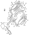
- the device (1) has two stationary processing tables (2, 3), which are arranged horizontally next to one another and rest on a device frame (not shown here). There is a frame on the top of each of the processing tables (2, 3) (4, 5) fixed. In the frame (4) lying first in the machining direction, vertically upright punching knives - designated by way of example (6) - are arranged. In the other frame (5) there are also vertically upstanding embossing strips - designated by way of example with (7) - the embossing stamp.
- two cylindrical pressure rollers (8, 9) are arranged in such a way that their roller shells (10 ⁇ , 11) have horizontal surface lines. They can be moved horizontally in the directions of the double arrows (A, B), these directions being inclined at a small angle to the sides of the frames (4, 5).
- the stub axles (12, 13) and (14, 15) of the pressure rollers (8, 9) are guided in slot guides (not shown here) in such a way that they carry out a horizontal translation movement over the processing tables (2, 3). In Figure (1) they are located near the outer end points.
- crank rods (16, 17) or (18, 19) are connected to crank rods (16, 17) or (18, 19).
- crank rods (16, 17) or (18, 19) on one side each lead to a common crank mechanism (20 ⁇ , 21). Both crank drives (20 ⁇ , 21) are connected by a common drive shaft (22).
- crank mechanism (20 ⁇ ) seated at the free end of the drive shaft (22) has two crank disks (23, 24) which are connected via a crank pin (25) to which the crank rod (16) is articulated.
- crank pin (25) On the free outside of the outer crank disk (24) there is another crank pin (26) which is offset by 180 ° from the crank pin (25) and on which the crank rod (17) is articulated.
- crank mechanism (21) located on the other side has three crank disks (27, 28, 29), which are each connected via crank pins (30 ⁇ , 31) offset by 180 °. On one crank pin (30 ⁇ ) are the crank rod (19) and on the other crank pin (31) the crank rod (18) articulated.
- Another section of the drive shaft (22) adjoins the crank disk (29). It leads into the driven side of a stepping gear (32) and is connected on the inside to a driven pulley which carries on its jacket a plurality of roller bolts which are freely rotatable about axes extending in the radial direction.
- the roller bolts engage in a Globo ⁇ d roller, which carries cams on its jacket, on which the roller bolts are supported.
- the globoid roller is connected to an electric drive motor (34) via an input shaft (33).
- the drive motor (34) performs a constant rotary movement. This is converted into a stepping movement in the stepping gear (32).
- the drive shaft (22) carries out a rotary movement of 180 ° with each step. As this also causes the crank pins (25, 26, 30 ⁇ , 31) to be pivoted through 180 ⁇ °, the result is that the pressure rollers (8, 9) are moved from one dead center position to the other dead center position.
- the cams on the Globoid roller within the stepping gear (32) are shaped so that a gentle, i.e. smooth movement with low accelerations is guaranteed.
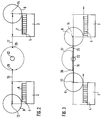
- FIGS. (2) and (3) The sequence of movements of the pressure rollers (8, 9) is illustrated in more detail in FIGS. (2) and (3).
- the crank rods (16, 17) are only shown as lines and the crank pins (25, 26) only as points.
- Figure (2) shows the position of the pressure rollers (8, 9) in the outermost dead center position, in which the roller shells (10 ⁇ , 11) of the pressure rollers (8, 9) no longer come into contact with the punching knives (6) or embossing strips (7) to have.
- the crankpin (25, 26) are accordingly located on the side of the crank rods (16, 17) articulated on them. In this position, a sheet blank can be placed on the punch knives (6) or embossing strips (7) with the aid of a conventional transport device, not shown here, in a precisely defined position.
- the transport device can be a transport device that moves over both processing tables (2, 3) in the plane of the drawing and that successively cuts into the device (1).
- the drive shaft (22) is turned by 180 °. Accordingly, the crank pins (25, 26) pivot by the same amount and then assume the position shown in Figure (3).
- the pressure rollers (8, 9) are moved over the punching knives (6) or embossing strips (7), whereby they exert such pressure on the blanks that the punching knives (6) cut through the blank and the embossing strips (7 ) Cause embossing, for example in the form of folds or embossing patterns.
- crank pins (26, 27) and the center point of the drive shaft is dimensioned such that when the drive shaft (22) rotates 180 °, both pressure rollers (8, 9) are moved over the entire surface, which the frame (4 , 5) is narrowed down. The pressure rollers (8, 9) then assume the inner dead center position, as can be seen in FIG. (3).
- the punched blank is moved horizontally with the transport device from the first frame (4) to the second frame (5) and deposited there.
- the embossed blank located in the frame (5) is removed and, if necessary, fed to a further station for breaking out the punched sections.
- a new blank is placed on the punching knives (6) in the frame (4).
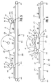
- the basic structure of the device (41) shown in FIG. 4 corresponds to the device (1) according to FIG. 1.
- the same reference numerals are therefore used for the same or functionally identical parts, reference being made in this respect to the description of the device (1) according to FIG. (1). Therefore, only the deviations from the device (1) according to FIG. (1) are described below.
- the device (41) no longer has a stepping gear. Rather, the drive motor (34) sits directly on the drive shaft (22) and drives the crank mechanisms (20 ⁇ ) and (21) directly.
- the stub axles (12, 13) or (14, 15) of the pressure rollers (8, 9) continue outwards beyond the crank rods (16, 17) or (18, 19).
- the stub axles (13, 15) on the side of the crank mechanism (21) end in rollers (42, 43) that roll on a support rail (44) over the entire range of motion of the pressure rollers (8, 9).
- the same is also provided at the ends of the opposite stub axles (12, 14). They also carry rollers (45, 46) that roll on a mounting rail (47).
- gear wheels (48, 49) are attached, which are non-rotatably connected to the stub axles (12, 14) and fit into a rack (50 ⁇ ) which runs parallel to the mounting rail (47). In this way it is ensured that the respective rotational positions of the pressure rollers (8, 9) are reproducible at the respective location.
- the pressure rollers (8, 9) are in contrast to the embodiment in the device (1) according to Figure (1) is not cylindrical. They each have cylindrical circumferential sections (51, 52) with a large diameter that extend over the entire width and cylindrical circumferential sections (53, 54) with a diameter that is smaller in comparison, the circumferential sections (51, 52, 53, 54) being transverse to the directions of movement A , B extending paragraphs (55, 56) or (57, 58) are connected.
- the meaning of this design of the pressure rollers (8, 9) is clear from the following description of the figures (5) and (6).
- the device (41) is shown schematically similar to the device (1) in Figures (2) and (3).
- the processing tables (2, 3) are also omitted here.
- the inclination of the pressure rollers (8, 9) has been omitted for reasons of clarity.
- the device (41) includes a transport device (59). It results from the figures (4) and (5).
- the transport device (59) has deflection rollers (60 ⁇ , 61) at its end points, one of which is driven and run over the endless chains (62).
- the endless chains (62) have transport brackets at regular intervals - designated by way of example (63) - which each protrude outwards. Perpendicular to the drawing level, i.e. transverse to the direction of movement of the endless chains (62) there are several - usually four - transport clamps.
- the transport clamps (63) serve to transport blanks introduced into the device (41) - designated by way of example with (64) - in the transport direction (arrow D) through the device (41) by the transport clamps (63) each comprise the front edge of a blank (64).
- the pressure rollers (8, 9) are in the outermost dead center position.
- the blanks in positions II and IV each lie on one of the processing tables (2, 3).
- the blank in position III (64) is held between the two processing tables (2, 3) while the blank (64) in position I is in a waiting position.
- the pressure rollers (8, 9) assume such a position that the peripheral sections (53, 54) with a small diameter are directed essentially downwards.
- the diameter of these peripheral sections (53, 54) is such that the transport clamps (63) and thus also the blanks (64) can pass under the pressure rollers (8, 9) without colliding with them.
- the pressure rollers (8, 9) have moved outwards beyond positions II and IV and thus over the processing tables (2, 3).
- the transport device (59) is actuated in such a way that a transport operation for displacing the blanks (64) takes place by an amount which moves them up by one position in the direction of arrow D, so that then the blanks (64) assume the positions shown in FIG.
- the pressure rollers (8, 9) are moved over the blanks (64) in positions (II and IV) and thus over the processing tables (2, 3).
- the circumferential sections (51, 52) with a large diameter then roll over the blanks (64), the transition from the circumferential sections (53, 54) with a small diameter to the circumferential sections (51, 52) with a large diameter being coordinated exactly in this way that the peripheral portions (51, 52) Roll up with a large diameter at the intended location while avoiding a collision with the transport clamps (63) on the blanks (64) and then roll on them.
- the deformations already described for the figures (2) and (3) are brought about.
- the basic structure of the device (71) shown in FIG. 7 corresponds to the device (41) according to FIG. 4 and - insofar as this is the same as the device (1) according to FIG. 1 - corresponds to it.
- the same reference numerals are therefore used for the same or functionally identical parts, reference being made to the description of the device (1) according to FIG. 1 or device (41) according to FIG. 4 for the explanation of the reference numbers. For this reason, only the deviations from the device (41) according to FIG. (4) are described below.
- the stub axles (12, 13) and (14, 15) now do not have - how in the embodiments according to the figures (1) and (4) - connection with crank rods, but are rotatably supported at the ends in carriages (72, 73, 74, 75). These slides (72, 73, 74, 75) run on guide rails (76, 77, 78, 79) which extend parallel to the rack (50 ⁇ ), which is divided here into rack sections (50 ⁇ a, 50 ⁇ b).
- Each carriage (72, 73, 74, 75) is permanently provided with a circumferential toothed belt (80 ⁇ , 81, 82, 83), each with its upper run above and with its lower run below the associated guide rail (76, 77, 78, 79) run.
- the toothed belts (80 ⁇ , 81, 82, 83) each loop around a toothed deflection roller (84, 85) or (86, 87) or (88, 89) or (90 ⁇ , 91). These are rotatably mounted, which is not shown here for the sake of clarity.
- the mutually facing deflection rollers (85, 88) and (87, 90 ⁇ ) carry spur gears (92, 93) and (94, 95).
- a pair of opposing spur gears (92, 93) or (94, 95) meshes with a pair of gears, each consisting of two intermeshing gears (96, 97) or (98, 99) of equal size.
- the left-hand gear (96) or (98) in this view meshes with another gear (10 ⁇ 0 ⁇ ) or (10 ⁇ 1) of larger diameter. Both other gears (10 ⁇ 0 ⁇ , 10 ⁇ 1) are rotatably connected to each other via a shaft (10 ⁇ 2).
- the other gear (10 ⁇ 1) in the foreground carries a pinion (10 ⁇ 3) which meshes with a drive gear (10 ⁇ 4) which has a much larger diameter than the pinion (10 ⁇ 3).
- This drive gear (10 ⁇ 4) is eccentrically connected to a crank rod (10 ⁇ 5), the other end of which is also eccentrically seated on a crank disk (10 ⁇ 6).
- the crank disc (10 ⁇ 6) is driven by an electric motor (34).
- the sequence of movements is basically similar to that in the device (41) according to the figures (4) to (6).
- the rotation of the crank disc (10 ⁇ 6) in the direction of arrow D periodically produces an up and down movement of the crank rod (10 ⁇ 5) (arrows E) and thus a back and forth rotation of the drive gear (10 ⁇ 4) by the angle indicated by the double arrow (F). It is possible to set this angle by radial adjustment of the pivot point of the crank rod (10 ⁇ 5) on the drive gear (10 ⁇ 4).
- the movement of this drive gear (10 ⁇ 4) is transmitted to the pinion (10 ⁇ 3) and from there to the further gear (10 ⁇ 1).
- the additional gear (10 (1) on the top side in this view also executes the same movement via the shaft (10 ⁇ 2).
- the other gears (10 ⁇ 0 ⁇ ) or (10 ⁇ 1) transmit the back and forth movement to the gears (96) or (98), which the movement on the one hand the spur gears (92, 94) and on the other hand to the adjacent gear (97, 99) pass on. The latter then mesh with the spur gears (93) and (95).
- the spur gears (92, 93) and (94, 95) perform opposite movements and transmit them to the toothed belts (80 ⁇ , 81, 82, 83) via the deflection rollers (85, 88; 87, 90 ⁇ ).
- the movement is such that a maximum speed is reached in the middle of the path, which does not decrease linearly towards the end points, however, because of the drive gear (10 ⁇ 4), crank rod (10 ⁇ 5) and crank disc (10 ⁇ 6) Crank drive.
- the pressure rollers (8, 9) are also not cylindrical, but correspond to those of the device (41) according to FIG. (4). This also applies to their movement over the processing tables (2, 3).
- the illustration of the transport device 59 is also missing in FIG. 7 for reasons of clarity. In this respect, there are also no deviations from the device (41) according to the figures (4) to (6).
Landscapes
- Engineering & Computer Science (AREA)
- Mechanical Engineering (AREA)
- Life Sciences & Earth Sciences (AREA)
- Forests & Forestry (AREA)
- Delivering By Means Of Belts And Rollers (AREA)
Applications Claiming Priority (4)
| Application Number | Priority Date | Filing Date | Title |
|---|---|---|---|
| DE9401787U | 1994-02-03 | ||
| DE9401787U DE9401787U1 (de) | 1994-02-03 | 1994-02-03 | Vorrichtung zur Verformung von Zuschnitten oder Bändern |
| DE9409555U | 1994-06-14 | ||
| DE9409555U DE9409555U1 (de) | 1994-02-03 | 1994-06-14 | Vorrichtung zur Verformung von Zuschnitten oder Bändern |
Publications (1)
| Publication Number | Publication Date |
|---|---|
| EP0666152A1 true EP0666152A1 (fr) | 1995-08-09 |
Family
ID=25961707
Family Applications (1)
| Application Number | Title | Priority Date | Filing Date |
|---|---|---|---|
| EP95101286A Withdrawn EP0666152A1 (fr) | 1994-02-03 | 1995-01-31 | Dispositif pour la déformation de flans ou de bandes |
Country Status (1)
| Country | Link |
|---|---|
| EP (1) | EP0666152A1 (fr) |
Cited By (1)
| Publication number | Priority date | Publication date | Assignee | Title |
|---|---|---|---|---|
| CN116100630A (zh) * | 2023-02-07 | 2023-05-12 | 山东春雨节水灌溉设备有限公司 | 一种外镶管件输水带的加工设备及加工工艺 |
Citations (6)
| Publication number | Priority date | Publication date | Assignee | Title |
|---|---|---|---|---|
| GB693507A (en) * | 1950-11-02 | 1953-07-01 | Collinson S Patents Ltd | Improvements in or relating to machines for cutting shapes from sheet material |
| CH593129A5 (en) * | 1974-03-21 | 1977-11-30 | Schroeter Friedrich | Cardboard box blank stamping machine - has resilient stamping tools advanced and released for return stroke by differentially shaped rolls |
| DE3216269A1 (de) * | 1982-04-30 | 1983-11-10 | Maschinen und Werkzeugbau Michael Brümmer GmbH, 8804 Dinkelsbühl | Vorrichtung zum ausschneiden von teilstuecken aus einer folie |
| EP0263545A1 (fr) * | 1986-10-07 | 1988-04-13 | INTERDIBIPACK S.p.A. | Machine pour couper des feuilles à l'aide d'un poinçon creuse |
| GB2224967A (en) * | 1988-09-07 | 1990-05-23 | Team Tool Company Limited | "Die-cutting presses" |
| JPH05131400A (ja) * | 1991-09-17 | 1993-05-28 | Jimuken:Kk | 切り込み付シート作成装置 |
-
1995
- 1995-01-31 EP EP95101286A patent/EP0666152A1/fr not_active Withdrawn
Patent Citations (6)
| Publication number | Priority date | Publication date | Assignee | Title |
|---|---|---|---|---|
| GB693507A (en) * | 1950-11-02 | 1953-07-01 | Collinson S Patents Ltd | Improvements in or relating to machines for cutting shapes from sheet material |
| CH593129A5 (en) * | 1974-03-21 | 1977-11-30 | Schroeter Friedrich | Cardboard box blank stamping machine - has resilient stamping tools advanced and released for return stroke by differentially shaped rolls |
| DE3216269A1 (de) * | 1982-04-30 | 1983-11-10 | Maschinen und Werkzeugbau Michael Brümmer GmbH, 8804 Dinkelsbühl | Vorrichtung zum ausschneiden von teilstuecken aus einer folie |
| EP0263545A1 (fr) * | 1986-10-07 | 1988-04-13 | INTERDIBIPACK S.p.A. | Machine pour couper des feuilles à l'aide d'un poinçon creuse |
| GB2224967A (en) * | 1988-09-07 | 1990-05-23 | Team Tool Company Limited | "Die-cutting presses" |
| JPH05131400A (ja) * | 1991-09-17 | 1993-05-28 | Jimuken:Kk | 切り込み付シート作成装置 |
Non-Patent Citations (1)
| Title |
|---|
| PATENT ABSTRACTS OF JAPAN vol. 17, no. 503 (M - 1478) 10 September 1993 (1993-09-10) * |
Cited By (3)
| Publication number | Priority date | Publication date | Assignee | Title |
|---|---|---|---|---|
| CN116100630A (zh) * | 2023-02-07 | 2023-05-12 | 山东春雨节水灌溉设备有限公司 | 一种外镶管件输水带的加工设备及加工工艺 |
| CN116100630B (zh) * | 2023-02-07 | 2023-09-12 | 山东春雨节水灌溉设备有限公司 | 一种外镶管件输水带的加工设备及加工工艺 |
| WO2024164805A1 (fr) * | 2023-02-07 | 2024-08-15 | 山东春雨节水灌溉设备有限公司 | Appareil et procédé d'usinage pour tuyau d'eau sur lequel est intégré par l'extérieur un raccord de tuyau |
Similar Documents
| Publication | Publication Date | Title |
|---|---|---|
| DE69203508T2 (de) | Maschine zum Schneiden von Materialbahnrollen. | |
| DE69204636T2 (de) | Tranferpresse mit quertrager. | |
| DE69012825T2 (de) | Vorrichtung zur herstellung seitlicher ausschnitte aus laufenden bahnen. | |
| EP0475202A1 (fr) | Dispositif pour plier des produits hygiéniques | |
| DE2627242A1 (de) | Vorrichtung zum kontinuierlichen oder halbkontinuierlichen schweissen von folienmaterialien | |
| CH700204A2 (de) | Trenn- und Abisoliereinrichtung für eine Kabelverarbeitungsmaschine. | |
| DE60029760T2 (de) | Verfahren und Vorrichtung zum Biegen von Laminatmaterial | |
| DE3016956C2 (de) | Flachschneidpresse | |
| DE2951427C2 (fr) | ||
| EP0053705A1 (fr) | Appareils de pliage pour machines rotatives d'impression de bandes | |
| DE2604729A1 (de) | Verfahren und maschine zur schrumpf- folien-verpackung | |
| AT393639B (de) | Blechbiegevorrichtung | |
| DE69101457T2 (de) | Vorrichtung zum Eindrücken und Schneiden in Längsrichtung eines laufenden Materialbandes. | |
| DE4335505C1 (de) | Vorrichtung zur Herstellung eines außen verzahnten Getriebeteiles | |
| DE3201836C2 (de) | Dreimesserschneidemaschine | |
| DE69108161T2 (de) | Verfahren und Vorrichtung zum Ausstrecken von Teig. | |
| DE3344797C2 (fr) | ||
| EP0666152A1 (fr) | Dispositif pour la déformation de flans ou de bandes | |
| DE9409555U1 (de) | Vorrichtung zur Verformung von Zuschnitten oder Bändern | |
| DE2649554A1 (de) | Vorrichtung zur herstellung von gegenstaenden aus einem plattenmaterial, insbesondere von gegenstaenden, welche ueber ihre gesamtlaenge hin ein konstantes profil aufweisen | |
| DE2258647A1 (de) | Presse mit zwei um die eine bzw. andere von zwei parallelen drehachsen synchron rotierenden werkzeugtraegern | |
| DE2062982A1 (de) | Papierlochmaschine | |
| CH680056A5 (fr) | ||
| DE3614575A1 (de) | Stanzvorrichtung | |
| DE2127788B2 (de) | Vorrichtung zum stirnseitigen Einfalten schlauchartig gefalteter Einwickelzuschnitte |
Legal Events
| Date | Code | Title | Description |
|---|---|---|---|
| PUAI | Public reference made under article 153(3) epc to a published international application that has entered the european phase |
Free format text: ORIGINAL CODE: 0009012 |
|
| 17P | Request for examination filed |
Effective date: 19950607 |
|
| AK | Designated contracting states |
Kind code of ref document: A1 Designated state(s): BE CH DE ES FR IT LI NL |
|
| STAA | Information on the status of an ep patent application or granted ep patent |
Free format text: STATUS: THE APPLICATION HAS BEEN WITHDRAWN |
|
| 18W | Application withdrawn |
Withdrawal date: 19980124 |