EP0666171A1 - Dispositif de serrage et de tension dans un cylindre porte-plaque d'une machine à imprimer rotative - Google Patents
Dispositif de serrage et de tension dans un cylindre porte-plaque d'une machine à imprimer rotative Download PDFInfo
- Publication number
- EP0666171A1 EP0666171A1 EP95100585A EP95100585A EP0666171A1 EP 0666171 A1 EP0666171 A1 EP 0666171A1 EP 95100585 A EP95100585 A EP 95100585A EP 95100585 A EP95100585 A EP 95100585A EP 0666171 A1 EP0666171 A1 EP 0666171A1
- Authority
- EP
- European Patent Office
- Prior art keywords
- rail
- clamping
- spring
- tensioning
- camshaft
- Prior art date
- Legal status (The legal status is an assumption and is not a legal conclusion. Google has not performed a legal analysis and makes no representation as to the accuracy of the status listed.)
- Granted
Links
- 230000004308 accommodation Effects 0.000 abstract 1
- 101150054854 POU1F1 gene Proteins 0.000 description 3
- 210000003746 feather Anatomy 0.000 description 1
- 238000000034 method Methods 0.000 description 1
Images
Classifications
-
- B—PERFORMING OPERATIONS; TRANSPORTING
- B41—PRINTING; LINING MACHINES; TYPEWRITERS; STAMPS
- B41F—PRINTING MACHINES OR PRESSES
- B41F27/00—Devices for attaching printing elements or formes to supports
- B41F27/12—Devices for attaching printing elements or formes to supports for attaching flexible printing formes
- B41F27/1218—Devices for attaching printing elements or formes to supports for attaching flexible printing formes comprising printing plate tensioning devices
- B41F27/1225—Devices for attaching printing elements or formes to supports for attaching flexible printing formes comprising printing plate tensioning devices moving in the printing plate end substantially rectilinearly
- B41F27/1231—Devices for attaching printing elements or formes to supports for attaching flexible printing formes comprising printing plate tensioning devices moving in the printing plate end substantially rectilinearly by translatory motion substantially tangential to support surface
Definitions
- the invention relates to a device for fastening flexible printing plates on a plate cylinder of rotary printing machines.
- a known embodiment of this type (DE 37 31 039 A1) discloses a clamping device for flexible pressure plates, in which lever elements clamp and tension the pressure plate via pneumatic or hydraulic elements.
- the object of the present invention is to simplify the clamping and tensioning of the pressure plate and to provide a device which ensures that the pressure plate is clamped and tensioned during operation of the machine without the supply of energy.
- the object is achieved by a device with the following solution features.
- the spring elements are arranged between the tensioning rail and camshaft and the spring-lever units are arranged between bearing arms on the tensioning rail and levers on the clamping rail.
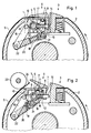
- a clamping device 3 for the leading plate end and a device 4 for attaching a flexible pressure plate 5 to the plate cylinder 2 are provided.
- the device 4 consists, inter alia, of an axially parallel clamping rail 6 arranged in the pit 1 and a clamping rail 7 fastened to the clamping rail 6.
- the clamping rail 6 is slidably mounted in the pit 1 of the plate cylinder 2 and carries bolts 8 at both ends which the clamping rail 7 is pivotally mounted.
- a camshaft 9 is provided, which is rotatably mounted in the end faces of the plate cylinder 2.
- the camshaft 9 carries two pairs of cams 10, 11, the pair of cams 10 displacing the tensioning rail 6 against the force of spring elements 12 via cam rollers 13.
- the spring elements 12 are provided on bolts 14, which are mounted in a longitudinally displaceable manner in the tensioning rail 6 and are supported with their opposite head 15 on the camshaft 9.
- the cam rollers 13 are attached to lever arms 16, which are also connected to the tensioning rail.
- the second pair of cams 11 presses when the camshaft is rotated counterclockwise, pins 17 which are fastened to the clamping rail 7, so that the clamping rail 7 opens and assumes the position shown in FIG. 2.
- the opening of the clamping rail 7 also takes place against the force of springs 18, which are actuated by levers 19, which in turn are attached to the clamping rail 7.
- the springs 18 can be actuated via plungers 20, which are fastened on one side via pins 21 to the levers 19 and on the other side via pins 22 on the bearing arms 16.
- Fig. 1 the pressure plate 5 is clamped between the clamping rail 6 and the clamping rail 7 and the clamping rail with the clamping rail is displaced to the right by the force of the spring elements 12, so that the pressure plate 5 is clamped on the outer surface of the plate cylinder 2.
- the camshaft 9 is rotated clockwise in its starting position (as shown). If the camshaft 9 is now rotated counterclockwise, the tensioning rail 6 with the clamping rail 7 is first moved to the left via the cam roller 13 and the pressure plate is thus relaxed. The clamping rail 7 is then opened via the second pair of cams 11 and the pins 17, as shown in FIG. 2. Here, the tensioning rail 6 is in its left starting position.
- a new printing plate 5 is now placed on the plate cylinder 2, it is first clamped by the clamping device 3 at its front end and pressed onto the outer surface of the plate cylinder 2 by rotating the plate cylinder 2 counterclockwise by means of rollers 23 fixedly mounted on the side frames.
- the rollers 23 press the trailing plate end 24 into the position shown, so that the wide-opening clamping rail 7 can be closed and the plate end 24 clamped, as shown in FIG 1 is shown.
- the pressure plate is tensioned by moving the tensioning rail 6 with the clamping rail 7 to the right.
Landscapes
- Supply, Installation And Extraction Of Printed Sheets Or Plates (AREA)
- Inking, Control Or Cleaning Of Printing Machines (AREA)
- Manufacture Or Reproduction Of Printing Formes (AREA)
Applications Claiming Priority (2)
| Application Number | Priority Date | Filing Date | Title |
|---|---|---|---|
| DE9401760U DE9401760U1 (de) | 1994-02-03 | 1994-02-03 | Plattenzylinder von Rotationsdruckmaschinen |
| DE9401760U | 1994-02-03 |
Publications (2)
| Publication Number | Publication Date |
|---|---|
| EP0666171A1 true EP0666171A1 (fr) | 1995-08-09 |
| EP0666171B1 EP0666171B1 (fr) | 1997-09-03 |
Family
ID=6904069
Family Applications (1)
| Application Number | Title | Priority Date | Filing Date |
|---|---|---|---|
| EP95100585A Expired - Lifetime EP0666171B1 (fr) | 1994-02-03 | 1995-01-18 | Dispositif de serrage et de tension dans un cylindre porte-plaque d'une machine à imprimer rotative |
Country Status (5)
| Country | Link |
|---|---|
| US (1) | US5495804A (fr) |
| EP (1) | EP0666171B1 (fr) |
| JP (1) | JP3014242U (fr) |
| AT (1) | ATE157597T1 (fr) |
| DE (2) | DE9401760U1 (fr) |
Families Citing this family (6)
| Publication number | Priority date | Publication date | Assignee | Title |
|---|---|---|---|---|
| DE29601400U1 (de) * | 1996-01-27 | 1996-03-07 | MAN Roland Druckmaschinen AG, 63075 Offenbach | Vorrichtung zum Lagefixieren und Lösen von drehbar gelagerten Teilen in Druckmaschinen |
| JPH1120131A (ja) * | 1997-07-03 | 1999-01-26 | Ryobi Ltd | 印刷機の刷版咥え装置 |
| JP2001260320A (ja) * | 2000-03-14 | 2001-09-25 | Fuji Photo Film Co Ltd | 可撓性刷版の装着方法および装着装置 |
| DE102008047191A1 (de) * | 2007-10-01 | 2009-04-02 | Heidelberger Druckmaschinen Ag | Vorrichtung zum Befestigen einer Druckplatte auf einem Plattenzylinder einer Druckmaschine |
| DE202018001624U1 (de) | 2018-03-28 | 2019-07-03 | Herold Maschinenbau Gmbh | Klemmvorrichtung zur Befestigung von Druckplatten auf einem Plattenzylinder |
| CN118810228B (zh) * | 2024-09-18 | 2025-01-10 | 德化县万顺印刷有限责任公司 | 印刷机的半自动装版系统 |
Citations (4)
| Publication number | Priority date | Publication date | Assignee | Title |
|---|---|---|---|---|
| US3156184A (en) * | 1962-02-20 | 1964-11-10 | Harris Intertype Corp | Plate clamp |
| DE2031711A1 (de) * | 1969-07-01 | 1971-01-07 | Baker Perkins Ltd , Peterborough, Northamptonshire (Großbritannien) | Druckplatten Festspannvornchtung |
| EP0444219A1 (fr) * | 1990-02-24 | 1991-09-04 | Komori Corporation | Dispositif pour l'enclenchement des plaques dans une presse |
| EP0544382A1 (fr) * | 1991-11-13 | 1993-06-02 | Komori Corporation | Dispositif de serrage d'une plaque d'impression pour machine à imprimer |
Family Cites Families (10)
| Publication number | Priority date | Publication date | Assignee | Title |
|---|---|---|---|---|
| CA563729A (fr) * | 1958-09-23 | Addressograph-Multigraph Corporation | Agrafe pour feuilles maitresses de machines rotatives a imprimer | |
| US2822754A (en) * | 1950-05-29 | 1958-02-11 | William F Huck | Plate lock-up mechanisms for printing machines |
| DE1248062B (de) * | 1963-06-22 | 1967-08-24 | Adamovske Strojirny Np | Klemmgreifereinrichtung am Druckzylinder von Druckmaschinen |
| FR2147392A5 (fr) * | 1971-07-26 | 1973-03-09 | Hugonnier Charles | |
| DE3731039A1 (de) * | 1987-09-16 | 1989-03-30 | Koenig & Bauer Ag | Einrichtung zum klemmen biegsamer druckplatten auf dem plattenzylinder einer rotationsdruckmaschine |
| EP0492138B1 (fr) * | 1990-12-21 | 1995-11-15 | Heidelberger Druckmaschinen Aktiengesellschaft | Dispositif de fixation rapide |
| DE59103503D1 (de) * | 1990-12-31 | 1994-12-15 | Heidelberger Druckmasch Ag | Klemm- und Spanneinrichtung. |
| US5142305A (en) * | 1991-03-04 | 1992-08-25 | Eastman Kodak Company | Apparatus for clamping and ejecting a receiver in a printing operation |
| DE4214168C2 (de) * | 1992-04-30 | 1994-10-06 | Roland Man Druckmasch | Vorrichtung zum Aufspannen von Druckplatten auf dem Plattenzylinder von Druckmaschinen, insbesondere Bogenoffsetdruckmaschinen |
| DE4244279C2 (de) * | 1992-12-28 | 1995-05-18 | Heidelberger Druckmasch Ag | Druckformkorrektureinrichtung zum Ausgleich von Druckträgerdehnungen |
-
1994
- 1994-02-03 DE DE9401760U patent/DE9401760U1/de not_active Expired - Lifetime
-
1995
- 1995-01-18 EP EP95100585A patent/EP0666171B1/fr not_active Expired - Lifetime
- 1995-01-18 AT AT95100585T patent/ATE157597T1/de active
- 1995-01-18 DE DE59500576T patent/DE59500576D1/de not_active Expired - Fee Related
- 1995-02-02 JP JP1995000318U patent/JP3014242U/ja not_active Expired - Lifetime
- 1995-02-03 US US08/383,077 patent/US5495804A/en not_active Expired - Fee Related
Patent Citations (4)
| Publication number | Priority date | Publication date | Assignee | Title |
|---|---|---|---|---|
| US3156184A (en) * | 1962-02-20 | 1964-11-10 | Harris Intertype Corp | Plate clamp |
| DE2031711A1 (de) * | 1969-07-01 | 1971-01-07 | Baker Perkins Ltd , Peterborough, Northamptonshire (Großbritannien) | Druckplatten Festspannvornchtung |
| EP0444219A1 (fr) * | 1990-02-24 | 1991-09-04 | Komori Corporation | Dispositif pour l'enclenchement des plaques dans une presse |
| EP0544382A1 (fr) * | 1991-11-13 | 1993-06-02 | Komori Corporation | Dispositif de serrage d'une plaque d'impression pour machine à imprimer |
Also Published As
| Publication number | Publication date |
|---|---|
| ATE157597T1 (de) | 1997-09-15 |
| EP0666171B1 (fr) | 1997-09-03 |
| US5495804A (en) | 1996-03-05 |
| JP3014242U (ja) | 1995-08-08 |
| DE9401760U1 (de) | 1994-03-17 |
| DE59500576D1 (de) | 1997-10-09 |
Similar Documents
| Publication | Publication Date | Title |
|---|---|---|
| DE3606351C2 (fr) | ||
| EP1029672B1 (fr) | Procédé et dispositif pour ajuster la force de pressage entre des rouleaux d'une machine à imprimer | |
| DE3936458C1 (fr) | ||
| EP0304646B1 (fr) | Dispositif pour fixer un cliché flexible sur le cylindre porte-plaque d'une machine à imprimer rotative | |
| WO2004028810A1 (fr) | Dispositifs et procédés de réglage de la pression d'appui d'un cylindre monté de manière réglable | |
| EP0666171B1 (fr) | Dispositif de serrage et de tension dans un cylindre porte-plaque d'une machine à imprimer rotative | |
| DE2932887C2 (de) | Rotationsdruckmaschine mit einer Einrichtung zur Verhinderung von Zylinderbewegungen | |
| DE2713994C2 (de) | Bogenhaltevorrichtung einer Bogen- Rotations-Druckmaschine, welche den Druckbogen geringfügig zu verformen vermag | |
| DE4321751C1 (de) | Vorrichtung zum paßgenauen Spannen von Druckplatten auf dem Plattenzylinder von Druckmaschinen | |
| DE4401684C2 (de) | Verstelleinrichtung für eine Druckmaschine | |
| DE4341431C2 (de) | Vorrichtung zum Klemmen und Spannen von biegsamen Druckplatten | |
| EP0741024A2 (fr) | Dispositif pour serrer et séparer des rouleaux | |
| EP0175237B1 (fr) | Dispositif d'enlèvement des rouleaux d'encrage dans les machines d'impression | |
| DE3812137A1 (de) | Vorrichtung zum befestigen einer biegsamen druckplatte | |
| DE2946597C2 (de) | Einspannvorrichtung für biegsame Druckplatten | |
| DE19753820A1 (de) | Vorrichtung zum gegenseitigen Anstellen von Druckwerkzylindern | |
| DE19829875A1 (de) | Vorrichtung zum Spannen einer Kante einer Platte für eine Druckmaschine | |
| DE69806105T2 (de) | Abhebevorrichtung für Farbauftragswalzen in einer Druckmaschine | |
| EP0005435B1 (fr) | Procédé pour obtenir une impression avec plusieurs couleurs avec recouvrement exact des couleurs | |
| DE10244046B4 (de) | Vorrichtung zum Einstellen des Anpressdrucks einer verstellbar gelagerten Walze | |
| DE19507368C1 (de) | Vorrichtung zum Spannen von Druckformen auf dem Formzylinder einer Rotationsdruckmaschine | |
| DE2944272C2 (de) | Vorrichtung zur An- und Abstellung des Gummituchzylinders einer Bogen-Rotations-Offsetdruckmaschine | |
| DE4324746A1 (de) | Einrichtung zum Sperren von Funktionsgruppen | |
| DE4134310C2 (de) | Einrichtung zum Schnellaufspannen von Druckplatten | |
| DE133969C (fr) |
Legal Events
| Date | Code | Title | Description |
|---|---|---|---|
| PUAI | Public reference made under article 153(3) epc to a published international application that has entered the european phase |
Free format text: ORIGINAL CODE: 0009012 |
|
| 17P | Request for examination filed |
Effective date: 19950118 |
|
| AK | Designated contracting states |
Kind code of ref document: A1 Designated state(s): AT CH DE FR GB LI |
|
| 17Q | First examination report despatched |
Effective date: 19950919 |
|
| GBC | Gb: translation of claims filed (gb section 78(7)/1977) | ||
| GRAG | Despatch of communication of intention to grant |
Free format text: ORIGINAL CODE: EPIDOS AGRA |
|
| GRAH | Despatch of communication of intention to grant a patent |
Free format text: ORIGINAL CODE: EPIDOS IGRA |
|
| GRAH | Despatch of communication of intention to grant a patent |
Free format text: ORIGINAL CODE: EPIDOS IGRA |
|
| GRAA | (expected) grant |
Free format text: ORIGINAL CODE: 0009210 |
|
| AK | Designated contracting states |
Kind code of ref document: B1 Designated state(s): AT CH DE FR GB LI |
|
| REF | Corresponds to: |
Ref document number: 157597 Country of ref document: AT Date of ref document: 19970915 Kind code of ref document: T |
|
| REG | Reference to a national code |
Ref country code: CH Ref legal event code: EP |
|
| REF | Corresponds to: |
Ref document number: 59500576 Country of ref document: DE Date of ref document: 19971009 |
|
| GBT | Gb: translation of ep patent filed (gb section 77(6)(a)/1977) |
Effective date: 19971106 |
|
| ET | Fr: translation filed | ||
| PLBE | No opposition filed within time limit |
Free format text: ORIGINAL CODE: 0009261 |
|
| STAA | Information on the status of an ep patent application or granted ep patent |
Free format text: STATUS: NO OPPOSITION FILED WITHIN TIME LIMIT |
|
| 26N | No opposition filed | ||
| PGFP | Annual fee paid to national office [announced via postgrant information from national office to epo] |
Ref country code: AT Payment date: 19990127 Year of fee payment: 5 |
|
| PGFP | Annual fee paid to national office [announced via postgrant information from national office to epo] |
Ref country code: CH Payment date: 19990210 Year of fee payment: 5 |
|
| PG25 | Lapsed in a contracting state [announced via postgrant information from national office to epo] |
Ref country code: AT Free format text: LAPSE BECAUSE OF NON-PAYMENT OF DUE FEES Effective date: 20000118 |
|
| PG25 | Lapsed in a contracting state [announced via postgrant information from national office to epo] |
Ref country code: LI Free format text: LAPSE BECAUSE OF NON-PAYMENT OF DUE FEES Effective date: 20000131 Ref country code: CH Free format text: LAPSE BECAUSE OF NON-PAYMENT OF DUE FEES Effective date: 20000131 |
|
| REG | Reference to a national code |
Ref country code: CH Ref legal event code: PL |
|
| REG | Reference to a national code |
Ref country code: GB Ref legal event code: IF02 |
|
| PGFP | Annual fee paid to national office [announced via postgrant information from national office to epo] |
Ref country code: GB Payment date: 20021224 Year of fee payment: 9 |
|
| PGFP | Annual fee paid to national office [announced via postgrant information from national office to epo] |
Ref country code: FR Payment date: 20030116 Year of fee payment: 9 |
|
| PG25 | Lapsed in a contracting state [announced via postgrant information from national office to epo] |
Ref country code: GB Free format text: LAPSE BECAUSE OF NON-PAYMENT OF DUE FEES Effective date: 20040118 |
|
| GBPC | Gb: european patent ceased through non-payment of renewal fee |
Effective date: 20040118 |
|
| PG25 | Lapsed in a contracting state [announced via postgrant information from national office to epo] |
Ref country code: FR Free format text: LAPSE BECAUSE OF NON-PAYMENT OF DUE FEES Effective date: 20040930 |
|
| REG | Reference to a national code |
Ref country code: FR Ref legal event code: ST |
|
| PGFP | Annual fee paid to national office [announced via postgrant information from national office to epo] |
Ref country code: DE Payment date: 20070102 Year of fee payment: 13 |
|
| PG25 | Lapsed in a contracting state [announced via postgrant information from national office to epo] |
Ref country code: DE Free format text: LAPSE BECAUSE OF NON-PAYMENT OF DUE FEES Effective date: 20080801 |