EP0666204B1 - Enrouleur pour une ceinture de sécurité - Google Patents
Enrouleur pour une ceinture de sécurité Download PDFInfo
- Publication number
- EP0666204B1 EP0666204B1 EP95100317A EP95100317A EP0666204B1 EP 0666204 B1 EP0666204 B1 EP 0666204B1 EP 95100317 A EP95100317 A EP 95100317A EP 95100317 A EP95100317 A EP 95100317A EP 0666204 B1 EP0666204 B1 EP 0666204B1
- Authority
- EP
- European Patent Office
- Prior art keywords
- bearing
- retractor according
- winding shaft
- automatic retractor
- frame
- Prior art date
- Legal status (The legal status is an assumption and is not a legal conclusion. Google has not performed a legal analysis and makes no representation as to the accuracy of the status listed.)
- Expired - Lifetime
Links
- 238000004804 winding Methods 0.000 claims abstract description 65
- 230000000903 blocking effect Effects 0.000 claims description 28
- 238000003466 welding Methods 0.000 claims description 4
- 238000000926 separation method Methods 0.000 claims description 2
- 230000037431 insertion Effects 0.000 claims 2
- 238000003780 insertion Methods 0.000 claims 2
- 238000006073 displacement reaction Methods 0.000 description 2
- 238000004519 manufacturing process Methods 0.000 description 2
- 230000036316 preload Effects 0.000 description 2
- 238000005096 rolling process Methods 0.000 description 2
- 238000003860 storage Methods 0.000 description 2
- 238000009434 installation Methods 0.000 description 1
- 238000005304 joining Methods 0.000 description 1
Images


Classifications
-
- B—PERFORMING OPERATIONS; TRANSPORTING
- B60—VEHICLES IN GENERAL
- B60R—VEHICLES, VEHICLE FITTINGS, OR VEHICLE PARTS, NOT OTHERWISE PROVIDED FOR
- B60R22/00—Safety belts or body harnesses in vehicles
- B60R22/34—Belt retractors, e.g. reels
- B60R22/36—Belt retractors, e.g. reels self-locking in an emergency
Definitions
- the invention relates to an automatic retractor for a seat belt according to the preamble of claim 1.
- Such an automatic reel-up is known from DE 39 40 374 A1.
- This automatic reel-up has a bearing device which is formed from two bearing shells which are connected to one another by plug connections and are arranged on the two winding shaft sides.
- the bearing shell on one side of the winding shaft receives a mainspring, under the influence of which the winding shaft can be rotated for the seat belt to be unwound and unwound.
- the bearing shell on the other side of the winding accommodates a sensor device which, in a known manner, is vehicle-sensitive and belt-strap-sensitive.
- the winding shaft is supported on both sides in smooth-running bearings, for example tip bearings, in the bearing shells.
- the winding shaft has locking teeth on both sides of the winding shaft which, in the event of locking, engage in corresponding locking teeth on the frame, the bearing device with the winding shaft arranged therein being pre-blocked against further rotation Frame is pivoted.
- the object of the invention is to provide an automatic reel-up of the type mentioned at the beginning, in which a problem-free swivel mounting of the bearing device is achieved.
- bearing edges and the plug connection, on which the bearing device rests in the bearing edges can advantageously be covered by a cover which is fastened to the frame and protected against falling out of the bearing edges.
- the bearing edges can advantageously be formed as fillets in which the plug connection of the bearing device can slide in the region of its bearing surfaces, which have a round contour.
- the bearing edges preferably have an elliptical hollow profile.
- the contact surfaces of the plug connection which come into contact with the bearing edges, can also have an elliptical shape with a somewhat greater curvature, so that the slidability on the bearing edges is achieved. In this way one achieves avoiding a clash a perfect locking engagement from the tip and tip of the locking teeth on the winding shaft and the frame legs.
- This separation of the blocking teeth can be prevented by another measure.
- This consists in that a train connection is provided between the free ends of the two frame legs and a frame part, which is connected, for example, by screwing to the vehicle body, which can also be designed as a cover for the winding shaft in the form of a cover plate.
- This train connection absorbs tensile forces which occur between the frame legs projecting approximately at right angles from the frame part fastened to the vehicle body and the frame part fastened to the vehicle body. If these tensile forces during the locking engagement of the winding shaft are so high that they deform the covering connecting plate, this connecting plate additionally presses the winding shaft into the blocking teeth on the two frame legs. This ensures that even at extremely high, a correct blocking of the winding shaft is maintained on the tensile forces acting on the tension band.
- the nested connecting parts of the plug connection can have conical contact surfaces.
- the conical contact surfaces have a preferably flat slope. Furthermore, they can be plastically deformable. In this way, regardless of tolerances, a reliable joining of the plug connection to form the bearing device for the winding shaft, the sensor device and the drive spring is achieved. In this way, easy assembly of the lifting roller machine is achieved.
- the preload with which the two bearing shells, Via which preferably three plug connections are connected to one another, is preferably maintained by a stop welded onto one of the two plug parts.
- the conicity of the abutting surfaces of the plug parts of the plug connection is approximately 0.5 to 1.0 °.
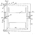
- the lifting roller machine shown has a winding shaft 1 for a seat belt.
- the winding shaft 1 is supported on both sides in smooth-running bearings, which can be designed, for example, as a tip bearing or a fine bearing and are formed by bearing elements 21, 22 on the winding shaft and on bearing shells 23, 24.
- the bearing shells are joined to form a structural unit or bearing device 8 by means of plug connections 9, which in the exemplary embodiment shown are designed as pins.
- the bearing shell 23 receives a sensor device, of which the vehicle-sensitive sensor 16 is shown.
- An inner ring gear 25 on the bearing shell 23 can interact with a belt-sensitive sensor device 29 mounted on the winding shaft 1.
- the winding shaft 1 is rotatably coupled to the bearing shell 23 or the bearing device 8 by the vehicle-sensitive sensor 16 and / or the belt-strap-sensitive sensor 29.
- the bearing shell 24 on the other winding shaft side receives a mainspring 2, which is supported at its outer end on the bearing shell 24 and engages at the bearing element 21 of the winding shaft 1 with its inner end. Under the influence of the mainspring 2, the seat belt, not shown, is wound up and unwound onto the winding shaft 1, the winding shaft 1 rotating about the shaft axis 3.
- the connecting parts 14, 15, which in the exemplary embodiment shown are designed as a continuous bore (in FIG. 2) with a conical inner wall and a correspondingly conically shaped insert part, are pushed into one another.
- the inner wall of the bore and the outer conical surface of the insert come into contact with each other. This contact occurs when the two bearing shells 23 and 24 are at a slightly greater distance from one another than the nominal distance X (FIG. 2).
- the two connecting parts 14, 15 (through hole and tapered insert) can come into contact with each other if the distance between the two Bearing cups 23 and 24 is approximately X + 2 mm.
- the bearing device 8 assembled from the two bearing shells 23, 24 via the plug connections 9 is pivotably mounted on a frame 6.
- the pivotable mounting takes place on bearing edges 10, which are provided on frame legs 7 of the frame 6.
- the bearing edges 10 are located on the outside of the two frame legs 7 with respect to the shaft axis 3.
- the bearing edges 10, which are preferably formed with an elliptical profile, are located in the immediate vicinity of free ends 26, 27 of frame leg parts which protrude from the frame approximately at right angles in the form of two cantilever arms.
- the remaining part of the frame 6 is formed by a frame part 28, in the area of which the frame 6 is fastened to the vehicle body with the aid of a screw connection and frame leg parts running approximately in the tape running direction, which merge into the two cantilever arms of the frame legs projecting at right angles.
- the winding shaft has blocking teeth 4 on its two sides.
- Corresponding blocking teeth 5 are arranged on the inside of the two frame legs 7 with respect to the shaft axis.
- the winding shaft pre-blocked by the sensor device on the bearing device 8 is brought into blocking engagement with the blocking toothing 5 on the frame legs 7 due to the pivoting bearing of the bearing device 8 on the bearing edges 10 with its blocking teeth 4.
- the forces exerted by the webbing are in the stable frame 6, which is on the vehicle chassis for example in the area of the B-pillar, attached to the frame part 28.
- the trough-shaped bearing edges 10, in particular trough-shaped or hollow grooves, ensure that the pin-shaped plug connections 9 are easily stored.
- the plug-in connection 9 embedded in the bearing edges 10 is overlapped by a cover 11 fastened to the frame, so that the plug-in connection 9 and the bearing device 8 located thereon are pivotably mounted on the bearing edges 10 in the manner of a swing.
- In their support areas 19 are from e.g. pin-shaped plug-in parts 12 and 13 plug connection 9 formed round to achieve a friction-free pivot bearing.
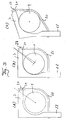
- the bearing edges 10 preferably have an elliptical profile (FIG. 4).
- the support areas 19 of the plug-in parts 12 and 13 can also have an elliptical contour, the curvature of the support areas 19 being greater than that of the bearing edges 10 in order to ensure that they are in perfect condition To ensure displacement of the connector 9 on the bearing edges 10.
- these parts can also have an outer contour adapted to one another, the elliptical shape being able to extend over the entire plug connection.
- a twist-free pushing of the plug parts 12 and 13 is hereby achieved.
- the mechanical stability, in particular the freedom from torsion of the plug connections 9 between the two bearing shells 23 and 24 is thereby increased.
- the plug-in parts 12 and 13 of the plug connection can also have the configuration of the conically matched surfaces which can be seen from the detailed drawing in FIG. 1.
- the pin-shaped plug part 13 has at its front end a tapered insert part 15 which can be inserted into a closed bore with a correspondingly shaped conical inner wall of the plug part 12.
- the tapered insert part 15 and the internally conically shaped bore 14 form connecting parts of the plug connection. Due to the conicity of the two plug-in parts 14 and 15, which runs in particular with a flat slope, the two pins 12 and 13 of the plug-in connection 9 are reliably joined together regardless of manufacturing tolerances. This can result in plastic deformations in the area of the interconnected connecting parts. After assembly, the nested parts are welded. Here ultrasonic welding is used in particular.
- additional plug connections (for example a total of 3 plug connections) can be provided in order to connect the two bearing shells 23 and 24 and the parts of the sensor device of the winding shaft and the drive spring arranged therebetween to form a structural unit.
- this structural unit or bearing device 8 is pivotably mounted on the frame 6.
- the winding shaft 1 is coupled in a known manner to the bearing device in a known manner, for example by means of a pawl engagement.
- a webbing pull acting on the pre-blocked winding shaft 1 pivots the bearing device. This swivel angle from the normal position, in which the winding shaft is freely rotatable and the webbing can be wound up and unwound under the influence of the mainspring 2, up to the blocking position, in which the blocking teeth 4 and 5 come into engagement with one another, can be approximately 3 ° .
- the blocking teeth 4 on the winding shaft can each have 36 teeth. This results in a control angle of 10 ° for the movement of the locking teeth 4 on the winding shaft into the frame-fixed locking teeth 5 on the frame 6 stand 36 Teeth on the winding shaft available. This can be the locking teeth on the sensor side of the winding shaft. However, an additional ring gear can also be provided on the winding shaft 1 for the sensor pin engagement.
- the arrangement of the bearing edges 10 and the locking teeth 5 on the frame legs 7 with respect to the control angle is dimensioned such that at least four locking teeth of the winding shaft with corresponding locking teeth on the frame come into blocking engagement while avoiding rolling out.
- a secure locking engagement of the locking teeth of the locking teeth 4 and 5 on the winding shaft 1 and the frame legs 7 is achieved.
- the meeting of the tip - tip of the teeth 4 and 5 is minimized.
- the displaceability of the bearing device 8 in the bearing edges 10 and the distance (angular distance) of the teeth of the blocking teeth 4 and 5 can be set so that when the winding shaft 1 is blocked, the teeth of the blocking teeth 4 and 5 always mesh when pivoting the bearing device 8, due to the displaceability of the storage is also ensured that these teeth are brought into an optimal locking engagement with each other by the band tension acting on the pre-blocked winding shaft 1.
- the cover 11 for covering the bearing on the bearing edges 10 can be formed in one piece with a cover plate, which forms a tension-absorbing connection 20 between the front ends 26 and 27 of the two frame legs 7 and the frame part 28.
- the connection 20, which is designed as a cover plate, is fastened on the one hand to the frame part 28 in a tensile manner and on the other hand in a tensile manner to fastening points 30, 31 in the region of the front ends of the frame legs 7 on the frame 6 (FIG. 3A). If, during the blocking engagement of the blocking teeth 4 and 5 (FIG.
- the webbing exerts high tensile forces on the winding shaft, which may lead to a deformation of the connection 20, the deformation is directed in the direction of the shaft axis 3 (FIG. 3C), so that the winding shaft 1 is displaced so that the locking teeth 4 and 5 remain in engagement with each other.
Landscapes
- Engineering & Computer Science (AREA)
- Mechanical Engineering (AREA)
- Automotive Seat Belt Assembly (AREA)
- Emergency Lowering Means (AREA)
Claims (17)
- Rétracteur pour une ceinture de sécurité, avec un enrouleur pour la ceinture de sécurité enroulable et déroulable, qui peut tourner autour d'un axe et est soumis à l'effet d'un ressort-moteur, avec des dentures de blocage sur les deux côtés de l'enrouleur qui s'engagent en cas de blocage, contre la force d'un ressort de rappel, dans des dentures de blocage correspondantes prévues sur des zones internes, par rapport à l'axe de l'enrouleur, des branches d'un cadre, et avec un système de palier formé de deux coussinets, reliés au moins par un assemblage à emboîtement, et qui reçoivent le ressort-moteur sur un côté de l'enrouleur et un dispositif de détection sensible sur l'autre côté, l'enrouleur étant logé sur ses deux côtés dans les coussinets, dans des paliers libres, et le système de palier étant monté avec une possibilité de pivotement sur le cadre, au moyen de l'assemblage à emboîtement, caractérisé en ce que le système de palier (8) est supporté sur des rebords d'appui (10) externes des extrémités libres des deux branches (7) du cadre.
- Rétracteur suivant la revendication 1, caractérisé en ce que les rebords d'appui (10) et l'assemblage à emboîtement (9), supporté sur ces derniers, du système de palier (8), sont fermés par un couvercle (11) fixé sur le cadre (6).
- Rétracteur suivant l'une des revendications 1 et 2, caractérisé en ce que chaque assemblage à emboîtement (9) se compose d'éléments enfichables (12, 13) emmanchés l'un dans l'autre, les éléments de jonction (14, 15) au moins, s'appliquant l'un sur l'autre, et des éléments enfichables (12, 13) présentant des surfaces de contact coniques.
- Rétracteur suivant l'une des revendications 1 à 3, caractérisé en ce que les éléments de jonction (14, 15), emmanchés l'un dans l'autre, sont formés par un trou muni d'une paroi interne conique et par un élément d'insertion se terminant en cône.
- Rétracteur suivant l'une des revendications 1 à 4, caractérisé en ce que les éléments de jonction (14, 15) sont assemblés entre eux par soudage.
- Rétracteur suivant l'une des revendications 1 à 5, caractérisé en ce que les éléments de jonction (14, 15) sont poussés l'un sur l'autre avec une précontrainte provoquée par leur conicité, et en ce qu'une butée (17) protège les deux éléments de jonction du risque de séparation, dans le sens de la précontrainte.
- Rétracteur suivant l'une des revendications 1 à 6, caractérisé en ce que l'un des éléments de jonction (14) est réalisé sous forme de trou continu, l'autre élément de jonction (15) étant réalisé sous forme d'élément d'insertion qui pénètre au travers de la totalité du trou, et sur une extrémité libre (18) duquel est prévue la butée (17).
- Rétracteur suivant l'une des revendications 1 à 7, caractérisé en ce que, par les éléments de jonction (14, 15) poussés l'un sur l'autre sous précontrainte, la distance axiale des deux coussinets de palier (23, 24) est réglée sur un jeu axial de palier optimal pour la souplesse de l'enrouleur (1).
- Rétracteur suivant l'une des revendications 1 à 8, caractérisé en ce que les éléments enfichables (12, 13) présentent, dans la zone de leurs éléments de jonction (14, 15) au moins, une section transversale qui diffère de la forme circulaire.
- Rétracteur suivant l'une des revendications 1 à 9, caractérisé en ce que les rebords d'appui (10) ont un profil creux, et en ce que l'assemblage à emboîtement (9) s'applique et peut glisser dans ses zones d'appui (19) sur les rebords d'appui (10).
- Rétracteur suivant l'une des revendications 1 à 10, caractérisé en ce que les rebords d'appui (10) ont un profil creux elliptique.
- Rétracteur suivant l'une des revendications 1 à 11, caractérisé en ce que l'assemblage à emboîtement (9) présente une section transversale elliptique, au moins dans ses zones d'appui (19) sur les rebords d'appui (10).
- Rétracteur suivant l'une des revendications 1 à 12, caractérisé en ce qu'un assemblage (20), soumis à une force de traction, est prévu entre les extrémités libres (26, 27) des deux branches (7) du cadre et une partie de cadre (28), assemblée avec la carrosserie.
- Rétracteur suivant la revendication 13, caractérisé en ce que, avec une déformation de l'assemblage (20) provoquée par une force de traction, l'enrouleur (1) est pressé dans les dentures de blocage (5) des branches (7) du cadre.
- Rétracteur suivant l'une des revendications 13 et 14, caractérisé en ce que l'assemblage (20), soumis à la force de traction, est réalisé sous forme de tôle de couverture et se compose d'une seule pièce avec le couvercle (11) des rebords d'appui (10).
- Rétracteur suivant l'une des revendications 1 à 15, caractérisé en ce que l'enrouleur peut être couplé sans possibilité de rotation au système de palier (8), au moyen du dispositif de détection sensible (16), et peut pivoter d'un angle de 3° environ, sous l'effet de la traction de la ceinture, pour l'entrée en prise des dentures de blocage (4, 5).
- Rétracteur suivant l'une des revendications 1 à 16, caractérisé en ce que chaque denture de blocage (4), prévue sur l'enrouleur (1), présente 36 dents.
Applications Claiming Priority (2)
| Application Number | Priority Date | Filing Date | Title |
|---|---|---|---|
| DE4403764A DE4403764C2 (de) | 1994-02-07 | 1994-02-07 | Aufrollautomat für einen Sicherheitsgurt |
| DE4403764 | 1994-02-07 |
Publications (3)
| Publication Number | Publication Date |
|---|---|
| EP0666204A2 EP0666204A2 (fr) | 1995-08-09 |
| EP0666204A3 EP0666204A3 (fr) | 1996-04-03 |
| EP0666204B1 true EP0666204B1 (fr) | 1997-11-05 |
Family
ID=6509671
Family Applications (1)
| Application Number | Title | Priority Date | Filing Date |
|---|---|---|---|
| EP95100317A Expired - Lifetime EP0666204B1 (fr) | 1994-02-07 | 1995-01-11 | Enrouleur pour une ceinture de sécurité |
Country Status (4)
| Country | Link |
|---|---|
| EP (1) | EP0666204B1 (fr) |
| AT (1) | ATE159902T1 (fr) |
| DE (2) | DE4403764C2 (fr) |
| ES (1) | ES2111343T3 (fr) |
Families Citing this family (1)
| Publication number | Priority date | Publication date | Assignee | Title |
|---|---|---|---|---|
| CN119022455B (zh) * | 2024-10-29 | 2024-12-20 | 东方空间技术(山东)有限公司 | 一种空调连接器撤收系统及撤收方法 |
Family Cites Families (5)
| Publication number | Priority date | Publication date | Assignee | Title |
|---|---|---|---|---|
| US3343765A (en) * | 1965-11-19 | 1967-09-26 | Gen Motors Corp | Seat belt retractor |
| US3552677A (en) * | 1968-12-16 | 1971-01-05 | Plastics Inc | Knockdown spool |
| ZA838354B (en) * | 1982-11-20 | 1984-06-27 | Britax Kolb Gmbh & Co | Safety belt emergency locking retractor |
| DE3940374C2 (de) * | 1989-12-06 | 1994-06-30 | Hs Tech & Design | Aufrollautomat für einen Sicherheitsgurt |
| JP2951735B2 (ja) * | 1991-03-11 | 1999-09-20 | タカタ株式会社 | シートベルトリトラクタ |
-
1994
- 1994-02-07 DE DE4403764A patent/DE4403764C2/de not_active Expired - Fee Related
-
1995
- 1995-01-11 DE DE59500925T patent/DE59500925D1/de not_active Expired - Fee Related
- 1995-01-11 EP EP95100317A patent/EP0666204B1/fr not_active Expired - Lifetime
- 1995-01-11 ES ES95100317T patent/ES2111343T3/es not_active Expired - Lifetime
- 1995-01-11 AT AT95100317T patent/ATE159902T1/de not_active IP Right Cessation
Also Published As
| Publication number | Publication date |
|---|---|
| EP0666204A2 (fr) | 1995-08-09 |
| DE4403764C2 (de) | 1996-06-05 |
| DE4403764A1 (de) | 1995-08-10 |
| EP0666204A3 (fr) | 1996-04-03 |
| ATE159902T1 (de) | 1997-11-15 |
| DE59500925D1 (de) | 1997-12-11 |
| ES2111343T3 (es) | 1998-03-01 |
Similar Documents
| Publication | Publication Date | Title |
|---|---|---|
| EP2512899B1 (fr) | Colonne de direction pour un véhicule à moteur | |
| DE69901603T2 (de) | Riemenspanner für ein kraftfahrzeug | |
| DE69506189T2 (de) | Drehbare Neigung | |
| EP0432420B1 (fr) | Articulation pour sièges à dossier réglable, en particulier pour sièges de véhicules automobiles | |
| DE60125992T2 (de) | Zubehörhalter in kabine | |
| DE19820641B4 (de) | Gurtaufwickeleinrichtung | |
| DE4307012C3 (de) | Sicherheitsgurt-Retraktor | |
| EP2547547B1 (fr) | Dispositif de réglage, en particulier dispositif de réglage en hauteur et en longueur pour des sièges automobiles | |
| DE4302739C2 (de) | Sicherheitsgurt-Retraktor | |
| EP0099549B1 (fr) | Ferrure articulée pour sièges de véhicules avec dossier réglable | |
| DE3636847C2 (fr) | ||
| EP0752350A1 (fr) | Rétracteur de sangle pour une ceinture de sécurité | |
| DE3124188A1 (de) | Gurtband-klemmvorrichtung fuer sicherheitsgurte in kraftfahrzeugen | |
| DE3873468T2 (de) | Sicherheitsgurthaltevorrichtung mit manueller lageverstellung. | |
| EP2709878B1 (fr) | Enrouleur de ceinture à denture de commande | |
| DE3546227C2 (fr) | ||
| EP0666204B1 (fr) | Enrouleur pour une ceinture de sécurité | |
| DE29923786U1 (de) | Antriebsvorrichtung für einen verstellbaren Rückblickspiegel mit einem selbstkalibrierenden Potentiometer | |
| EP3856609B1 (fr) | Colonne de direction réglable | |
| DE10126317C1 (de) | Drehsperre für einen Gurtumlenkbeschlag | |
| DE102011101964B4 (de) | Gurtspule mit Spitzenlagerung | |
| DE20212591U1 (de) | Gurtspule für einen Gurtaufroller | |
| DE19514741C2 (de) | Schwenkbare Lenkvorrichtung | |
| DE1456115A1 (de) | Selbstsperrende Aufwickelvorrichtung fuer einen Anschnallgurt | |
| EP0140366A2 (fr) | Dispositif enrouleur pour ceintures de sécurité |
Legal Events
| Date | Code | Title | Description |
|---|---|---|---|
| PUAI | Public reference made under article 153(3) epc to a published international application that has entered the european phase |
Free format text: ORIGINAL CODE: 0009012 |
|
| AK | Designated contracting states |
Kind code of ref document: A2 Designated state(s): AT DE ES FR GB IT NL SE |
|
| PUAL | Search report despatched |
Free format text: ORIGINAL CODE: 0009013 |
|
| AK | Designated contracting states |
Kind code of ref document: A3 Designated state(s): AT DE ES FR GB IT NL SE |
|
| 17P | Request for examination filed |
Effective date: 19960906 |
|
| 17Q | First examination report despatched |
Effective date: 19961011 |
|
| GRAG | Despatch of communication of intention to grant |
Free format text: ORIGINAL CODE: EPIDOS AGRA |
|
| GRAH | Despatch of communication of intention to grant a patent |
Free format text: ORIGINAL CODE: EPIDOS IGRA |
|
| GRAH | Despatch of communication of intention to grant a patent |
Free format text: ORIGINAL CODE: EPIDOS IGRA |
|
| GRAA | (expected) grant |
Free format text: ORIGINAL CODE: 0009210 |
|
| AK | Designated contracting states |
Kind code of ref document: B1 Designated state(s): AT DE ES FR GB IT NL SE |
|
| PG25 | Lapsed in a contracting state [announced via postgrant information from national office to epo] |
Ref country code: NL Free format text: LAPSE BECAUSE OF FAILURE TO SUBMIT A TRANSLATION OF THE DESCRIPTION OR TO PAY THE FEE WITHIN THE PRESCRIBED TIME-LIMIT Effective date: 19971105 Ref country code: FR Free format text: LAPSE BECAUSE OF FAILURE TO SUBMIT A TRANSLATION OF THE DESCRIPTION OR TO PAY THE FEE WITHIN THE PRESCRIBED TIME-LIMIT Effective date: 19971105 |
|
| REF | Corresponds to: |
Ref document number: 159902 Country of ref document: AT Date of ref document: 19971115 Kind code of ref document: T |
|
| REF | Corresponds to: |
Ref document number: 59500925 Country of ref document: DE Date of ref document: 19971211 |
|
| ITF | It: translation for a ep patent filed | ||
| PG25 | Lapsed in a contracting state [announced via postgrant information from national office to epo] |
Ref country code: AT Free format text: LAPSE BECAUSE OF NON-PAYMENT OF DUE FEES Effective date: 19980111 |
|
| PG25 | Lapsed in a contracting state [announced via postgrant information from national office to epo] |
Ref country code: SE Free format text: LAPSE BECAUSE OF FAILURE TO SUBMIT A TRANSLATION OF THE DESCRIPTION OR TO PAY THE FEE WITHIN THE PRESCRIBED TIME-LIMIT Effective date: 19980205 |
|
| GBT | Gb: translation of ep patent filed (gb section 77(6)(a)/1977) |
Effective date: 19980119 |
|
| REG | Reference to a national code |
Ref country code: ES Ref legal event code: FG2A Ref document number: 2111343 Country of ref document: ES Kind code of ref document: T3 |
|
| NLV1 | Nl: lapsed or annulled due to failure to fulfill the requirements of art. 29p and 29m of the patents act | ||
| EN | Fr: translation not filed | ||
| PLBE | No opposition filed within time limit |
Free format text: ORIGINAL CODE: 0009261 |
|
| STAA | Information on the status of an ep patent application or granted ep patent |
Free format text: STATUS: NO OPPOSITION FILED WITHIN TIME LIMIT |
|
| 26N | No opposition filed | ||
| REG | Reference to a national code |
Ref country code: GB Ref legal event code: IF02 |
|
| PGFP | Annual fee paid to national office [announced via postgrant information from national office to epo] |
Ref country code: ES Payment date: 20030129 Year of fee payment: 9 |
|
| PGFP | Annual fee paid to national office [announced via postgrant information from national office to epo] |
Ref country code: GB Payment date: 20031211 Year of fee payment: 10 |
|
| PG25 | Lapsed in a contracting state [announced via postgrant information from national office to epo] |
Ref country code: ES Free format text: LAPSE BECAUSE OF NON-PAYMENT OF DUE FEES Effective date: 20040112 |
|
| PGFP | Annual fee paid to national office [announced via postgrant information from national office to epo] |
Ref country code: DE Payment date: 20040130 Year of fee payment: 10 |
|
| PG25 | Lapsed in a contracting state [announced via postgrant information from national office to epo] |
Ref country code: IT Free format text: LAPSE BECAUSE OF NON-PAYMENT OF DUE FEES;WARNING: LAPSES OF ITALIAN PATENTS WITH EFFECTIVE DATE BEFORE 2007 MAY HAVE OCCURRED AT ANY TIME BEFORE 2007. THE CORRECT EFFECTIVE DATE MAY BE DIFFERENT FROM THE ONE RECORDED. Effective date: 20050111 Ref country code: GB Free format text: LAPSE BECAUSE OF NON-PAYMENT OF DUE FEES Effective date: 20050111 |
|
| REG | Reference to a national code |
Ref country code: ES Ref legal event code: FD2A Effective date: 20040112 |
|
| PG25 | Lapsed in a contracting state [announced via postgrant information from national office to epo] |
Ref country code: DE Free format text: LAPSE BECAUSE OF NON-PAYMENT OF DUE FEES Effective date: 20050802 |
|
| GBPC | Gb: european patent ceased through non-payment of renewal fee |
Effective date: 20050111 |