EP0666351A1 - Procédé et dispositif pour broder sur une machine à broder à navettes - Google Patents
Procédé et dispositif pour broder sur une machine à broder à navettes Download PDFInfo
- Publication number
- EP0666351A1 EP0666351A1 EP94117733A EP94117733A EP0666351A1 EP 0666351 A1 EP0666351 A1 EP 0666351A1 EP 94117733 A EP94117733 A EP 94117733A EP 94117733 A EP94117733 A EP 94117733A EP 0666351 A1 EP0666351 A1 EP 0666351A1
- Authority
- EP
- European Patent Office
- Prior art keywords
- thread
- needle
- embroidery
- shuttle
- delivery unit
- Prior art date
- Legal status (The legal status is an assumption and is not a legal conclusion. Google has not performed a legal analysis and makes no representation as to the accuracy of the status listed.)
- Granted
Links
- 238000000034 method Methods 0.000 title claims description 17
- 238000009956 embroidering Methods 0.000 title description 3
- 230000015572 biosynthetic process Effects 0.000 claims abstract description 18
- 239000004744 fabric Substances 0.000 claims abstract description 12
- 239000000463 material Substances 0.000 claims description 6
- 239000004020 conductor Substances 0.000 description 4
- 230000001419 dependent effect Effects 0.000 description 2
- 238000006073 displacement reaction Methods 0.000 description 2
- 230000035515 penetration Effects 0.000 description 2
- 239000000969 carrier Substances 0.000 description 1
- 230000007812 deficiency Effects 0.000 description 1
- 230000006866 deterioration Effects 0.000 description 1
- 239000000126 substance Substances 0.000 description 1
Images

Classifications
-
- D—TEXTILES; PAPER
- D05—SEWING; EMBROIDERING; TUFTING
- D05C—EMBROIDERING; TUFTING
- D05C11/00—Devices for guiding, feeding, handling, or treating the threads in embroidering machines; Machine needles; Operating or control mechanisms therefor
- D05C11/08—Thread-tensioning arrangements
-
- D—TEXTILES; PAPER
- D05—SEWING; EMBROIDERING; TUFTING
- D05C—EMBROIDERING; TUFTING
- D05C11/00—Devices for guiding, feeding, handling, or treating the threads in embroidering machines; Machine needles; Operating or control mechanisms therefor
- D05C11/02—Machine needles
- D05C11/06—Needle-driving or control mechanisms
-
- D—TEXTILES; PAPER
- D05—SEWING; EMBROIDERING; TUFTING
- D05B—SEWING
- D05B55/00—Needle holders; Needle bars
- D05B55/04—Devices for inserting needles
Definitions
- the invention relates to a method for embroidering with a shuttle embroidery machine according to the preamble of claim 1 and an apparatus for carrying out this method according to the preamble of claim 3.
- each thread loops around a role assigned to it, which engages with a brake shaft common to all embroidery points and which are decoupled from this brake shaft when the embroidery point in question is switched off can.
- Such an arrangement is known for example from DE-PS 34 16 266.
- the thread guides are arranged, which supply the thread quantity for loop formation and pull it back again. Furthermore, the type of movement of the thread conductors after the formation of a stitch creates a deficiency in the needle thread, which must be deliberately brought about in order to build up tension in the needle threads, which leads to a rotational movement of the rollers and the brake shaft and thus to a specific one Lots of needle thread leads. At the same time, the stitch formed is tightened with this thread tension in the needle thread. Braking the shaft is necessary in order to prevent the rollers and the shaft from running out in an uncontrolled manner, and thus to prevent an excessive amount of thread from being dispensed.
- a major disadvantage of this design is that the amount of thread supplied is insufficiently accurate, because the tension built up in the needle threads and thus the roll rotation depends on the thread consumption due to the formation of the previous stitch. As a result, the tightening tension with which the stitch formed is tightened is not constant, which results in unevenness in the embroidery pattern.
- the tensions in the needle threads increase further, which in turn results in an increase in thread breaks and a deterioration in the embroidery pattern.
- the tension in the needle threads increases more and more with increasing machine speed because the thread roller has to be moved in ever shorter times.
- the mode of operation of the device specified in this publication is limited to emulating the embroidery process as is known from conventional shuttle embroidery machines according to DE-PS 34 16 266.
- the method is also based on building up a thread tension in the needle thread during the process.
- EP-PS 0 014 897 teaches that by turning the roller back after the stitch formation, the stitch formed is tightened by tensioning the needle thread (page 4, column 6, lines 25 to 28). This process in turn leads to tensions in the needle threads, which limit the working speed and result in the occurrence of thread breaks.
- a needle thread length of about 100 millimeters has to be supplied from the roller and pulled back again for each stitch, which requires the use of thread stores in front of the roller and additional means which prevent the threads from uncontrollably being wrapped around by the threads if they are included run onto the roller at high speed and are released again by the roller.
- the present invention is based on the object of specifying an embroidery method in which there are no longer any thread tensions which limit the working speed.
- the thread guide and the delivery unit provide as much thread for each working needle as is required for the penetration of the needle into the fabric to be embroidered, for the formation of a needle thread loop and for the passage of the boat through this loop, as well as the amount of thread that is required remains on the embroidery after the stitch is formed.
- This total amount of thread is supplied by the thread guide and thread delivery unit in such a way that thread tension never occurs in the needle thread.
- the needle thread remains stretched throughout the stitch formation, but always free of tension.
- An essential feature of the invention is that the stitch formed is then tightened by the pulling force of the shuttle thread. Through this type of tightening the stitch formed, the needle thread remains tension-free even in this phase of the embroidery process.
- the thread delivery unit and the thread guide in such a way that the thread conductor has that thread quantity supplies that is required for the penetration of the needle into the fabric to be embroidered, for the formation of a needle thread loop and for the passage of the boat through this loop, while the thread delivery unit supplies the amount of thread that remains on the fabric after stitch formation.
- the quantities of the thread portions to be delivered by the two elements thread guide and thread delivery unit are selected in such a way that thread tension can never occur in the needle thread.
- the needle thread remains stretched throughout the stitch formation, but always free of tension.
- the stitch formed is then tightened solely by the pulling force of the shuttle thread and the needle thread remains tension-free even during the phase of the embroidery process in which the stitch is tightened.
- the thread delivery unit as a long motor-driven shaft, over which the threads of several embroidery points run.
- a thread roll is assigned to each thread, which conveys the thread between itself and the shaft by friction.
- This arrangement enables the needle threads to be inserted very easily and quickly on the embroidery machine because the time-consuming looping of a brake roller with the threads is eliminated.
- a stationary deflection point as a thread monitor in the thread course from the thread delivery unit to the needle.
- the thread monitor checks for the presence of the needle thread and, if it is missing, initiates a shutdown of the embroidery machine.
- the risk of breakage is very low due to the lack of thread tension in the needle thread, the use of thread monitors is useful for detecting empty needle thread bobbins or shuttle thread bobbins.
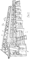
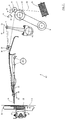
- the embroidery machine 1 has an embroidery frame 2, in which the fabric 3 to be embroidered is clamped.
- the embroidery material frame 2 can, as usual, be displaced in the directions 4 and 5 perpendicular to the plane of the material to produce the pattern.
- a control unit 6 controls the movements of the embroidery material frame 2 and of the motor 8, which drives the thread feed roller 7 in the direction 12.
- Each embroidery point 42 is assigned a thread roll 9 which is rotatably mounted on a lever 10.
- the lever 10 is mounted on the pivot point 11, so that the thread roll 9 is lifted off the roller 7 by pivoting the lever 10 in the direction 13 and by pivoting the Lever 10 in the direction 14 of the needle thread 35 between the thread roller 9 and the thread roller 7 is clamped by the action of the spring 15. In this position, the needle thread 35 is withdrawn from the bobbin 16 by rotation of the thread roller 7 and fed to the embroidery site.
- the control unit 6 also drives the thread guide 17, the needle carriers 22 and the shuttle 25 via drives (not shown).
- the thread guide is pivoted about the pivot point 18 in the directions 19 and 20.
- the needle carrier 22 carries the needle 21, which is guided in the direction 23 into the fabric 3 and in the direction 24 out of this.
- the shuttle 25 is slidably mounted on the shuttle carrier 26 in the directions 27 and 28. Between thread roller 7 and thread conductor 17, needle thread 35 loops around a stationary deflection point 29, which is designed as thread monitor 30.
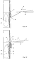
- 3a shows the start of stitch formation with the needle 21 which has penetrated into the fabric 3 and which enters the needle channel 33 through the stitch hole 31 in the embroidery plate 32.
- a brief movement of the needle 21 in the direction 24 creates a needle thread loop 43 between the needle eye 34 and the tap hole 31, through which the shuttle 25 with the shuttle thread 36 is pushed in the further course.
- the shuttle thread supply is located in the shuttle 25 and exits the shuttle 40 from the opening 40 when an adjustable tensile force is applied.
- the needle eye 34 of the needle 21 enters the substance 3 at the new puncture point 39.
- the shuttle 25 pulls through its further movement in direction 28 by pulling on the shuttle thread 36 in direction 41 the interlacing 37 of needle thread 35 and shuttle thread 36. Due to the multiple deflections of the needle thread at the new puncture point 39 and at the previous puncture point 38, the resulting tension cannot be transferred to that part of the needle thread 35 which lies in front of the needle eye 39 on the front of the fabric 3.
Landscapes
- Engineering & Computer Science (AREA)
- Textile Engineering (AREA)
- Sewing Machines And Sewing (AREA)
Applications Claiming Priority (2)
| Application Number | Priority Date | Filing Date | Title |
|---|---|---|---|
| DE4403365 | 1994-02-04 | ||
| DE4403365A DE4403365A1 (de) | 1994-02-04 | 1994-02-04 | Verfahren und Vorrichtung zum Sticken auf einer Schiffchen-Stickmaschine |
Publications (2)
| Publication Number | Publication Date |
|---|---|
| EP0666351A1 true EP0666351A1 (fr) | 1995-08-09 |
| EP0666351B1 EP0666351B1 (fr) | 1997-05-07 |
Family
ID=6509409
Family Applications (1)
| Application Number | Title | Priority Date | Filing Date |
|---|---|---|---|
| EP94117733A Expired - Lifetime EP0666351B1 (fr) | 1994-02-04 | 1994-11-10 | Procédé et dispositif pour broder sur une machine à broder à navettes |
Country Status (6)
| Country | Link |
|---|---|
| EP (1) | EP0666351B1 (fr) |
| JP (1) | JPH0835162A (fr) |
| KR (1) | KR950032807A (fr) |
| AT (1) | ATE152789T1 (fr) |
| DE (2) | DE4403365A1 (fr) |
| TR (1) | TR27803A (fr) |
Cited By (8)
| Publication number | Priority date | Publication date | Assignee | Title |
|---|---|---|---|---|
| EP0756031A3 (fr) * | 1995-07-26 | 1997-08-20 | Laesser Franz Ag | Dispositif guide fil pour machine à broder schiffli |
| EP0795638A1 (fr) * | 1996-03-15 | 1997-09-17 | Franz Lässer AG | Procédé et dispositif pour former le point dans une machine à broder Schiffli |
| EP0906982A3 (fr) * | 1997-10-03 | 2000-01-12 | Hiraoka Kogyo Co. Ltd. | Machine à broder |
| EP1160369A1 (fr) * | 2000-05-31 | 2001-12-05 | Franz Lässer AG | Machine à broder |
| EP1209273A3 (fr) * | 2000-11-21 | 2003-01-02 | Franz Lässer AG | Procédé de formation du point dans une machine à broder et machine à broder pour la mise en oeuvre dudit procédé |
| WO2003002801A1 (fr) * | 2001-06-27 | 2003-01-09 | Zsk Stickmaschinen Gmbh | Mecanisme d'entrainement du fil commande en fonction de la tension determinee du fil |
| EP1624100A1 (fr) | 2004-08-04 | 2006-02-08 | Lässer AG | Bâti pour machine à broder et son utilisation avec une fondation de bâti |
| CN114481481A (zh) * | 2021-06-11 | 2022-05-13 | 浙江信胜科技股份有限公司 | 缝制设备自动线量计算方法及输送系统 |
Families Citing this family (1)
| Publication number | Priority date | Publication date | Assignee | Title |
|---|---|---|---|---|
| JP2008214837A (ja) * | 2007-02-08 | 2008-09-18 | Miyagi Lace Co Ltd | エンブロイダリレースおよびエンブロイダリレース地、ならびにそれらの製造方法 |
Citations (5)
| Publication number | Priority date | Publication date | Assignee | Title |
|---|---|---|---|---|
| CH96452A (de) * | 1922-05-09 | 1922-10-16 | Rogg Bernhard | Schiffchenstickmaschine mit Steuerung für Steppstich und Plattstich. |
| DE401265C (de) * | 1924-08-30 | Vogtlaendische Maschinenfabrik | Einrichtung zur Erzielung eines gleichmaessigen Fadenanzuges bei Stickmaschinen | |
| US3460495A (en) * | 1967-05-29 | 1969-08-12 | Walter L Cobb | Method for embroidering tufts |
| DE3416266A1 (de) * | 1983-06-16 | 1984-12-20 | Aktiengesellschaft Adolph Saurer, Arbon | Schaltbare bremseinrichtung fuer die faeden einer stickmaschine |
| CH669414A5 (fr) * | 1985-03-02 | 1989-03-15 | Motema Textilmaschinen Ges Mbh |
Family Cites Families (4)
| Publication number | Priority date | Publication date | Assignee | Title |
|---|---|---|---|---|
| AT370144B (de) * | 1979-02-20 | 1983-03-10 | August Heinzle | Einrichtung zur zufuehrung und zum nachziehen des fadens an textilmaschinen |
| US4308812A (en) * | 1980-03-17 | 1982-01-05 | Harry Lenson | Embroidery machine having improved thread supply system |
| DD213705A1 (de) * | 1983-02-23 | 1984-09-19 | Plauener Spitze Veb | Fadenspann- und waechtervorrichtung fuer stickmaschinen |
| CH679050A5 (fr) * | 1987-10-31 | 1991-12-13 | Juki Kk |
-
1994
- 1994-02-04 DE DE4403365A patent/DE4403365A1/de not_active Withdrawn
- 1994-11-10 AT AT94117733T patent/ATE152789T1/de not_active IP Right Cessation
- 1994-11-10 DE DE59402665T patent/DE59402665D1/de not_active Ceased
- 1994-11-10 EP EP94117733A patent/EP0666351B1/fr not_active Expired - Lifetime
- 1994-12-13 TR TR01292/94A patent/TR27803A/xx unknown
-
1995
- 1995-02-01 JP JP7015378A patent/JPH0835162A/ja active Pending
- 1995-02-04 KR KR1019950002002A patent/KR950032807A/ko not_active Abandoned
Patent Citations (5)
| Publication number | Priority date | Publication date | Assignee | Title |
|---|---|---|---|---|
| DE401265C (de) * | 1924-08-30 | Vogtlaendische Maschinenfabrik | Einrichtung zur Erzielung eines gleichmaessigen Fadenanzuges bei Stickmaschinen | |
| CH96452A (de) * | 1922-05-09 | 1922-10-16 | Rogg Bernhard | Schiffchenstickmaschine mit Steuerung für Steppstich und Plattstich. |
| US3460495A (en) * | 1967-05-29 | 1969-08-12 | Walter L Cobb | Method for embroidering tufts |
| DE3416266A1 (de) * | 1983-06-16 | 1984-12-20 | Aktiengesellschaft Adolph Saurer, Arbon | Schaltbare bremseinrichtung fuer die faeden einer stickmaschine |
| CH669414A5 (fr) * | 1985-03-02 | 1989-03-15 | Motema Textilmaschinen Ges Mbh |
Cited By (10)
| Publication number | Priority date | Publication date | Assignee | Title |
|---|---|---|---|---|
| EP0756031A3 (fr) * | 1995-07-26 | 1997-08-20 | Laesser Franz Ag | Dispositif guide fil pour machine à broder schiffli |
| EP0795638A1 (fr) * | 1996-03-15 | 1997-09-17 | Franz Lässer AG | Procédé et dispositif pour former le point dans une machine à broder Schiffli |
| EP0906982A3 (fr) * | 1997-10-03 | 2000-01-12 | Hiraoka Kogyo Co. Ltd. | Machine à broder |
| EP1160369A1 (fr) * | 2000-05-31 | 2001-12-05 | Franz Lässer AG | Machine à broder |
| EP1209273A3 (fr) * | 2000-11-21 | 2003-01-02 | Franz Lässer AG | Procédé de formation du point dans une machine à broder et machine à broder pour la mise en oeuvre dudit procédé |
| WO2003002801A1 (fr) * | 2001-06-27 | 2003-01-09 | Zsk Stickmaschinen Gmbh | Mecanisme d'entrainement du fil commande en fonction de la tension determinee du fil |
| DE10130345A1 (de) * | 2001-06-27 | 2003-01-09 | Zsk Stickmasch Gmbh | In Abhängigkeit von der Fadenspannung angesteuerter Fadenantriebsmechanismus |
| EP1624100A1 (fr) | 2004-08-04 | 2006-02-08 | Lässer AG | Bâti pour machine à broder et son utilisation avec une fondation de bâti |
| CN114481481A (zh) * | 2021-06-11 | 2022-05-13 | 浙江信胜科技股份有限公司 | 缝制设备自动线量计算方法及输送系统 |
| CN114481481B (zh) * | 2021-06-11 | 2023-08-15 | 浙江信胜科技股份有限公司 | 缝制设备自动线量计算方法及输送系统 |
Also Published As
| Publication number | Publication date |
|---|---|
| EP0666351B1 (fr) | 1997-05-07 |
| ATE152789T1 (de) | 1997-05-15 |
| DE59402665D1 (de) | 1997-06-12 |
| DE4403365A1 (de) | 1995-08-10 |
| TR27803A (tr) | 1995-08-29 |
| KR950032807A (ko) | 1995-12-22 |
| JPH0835162A (ja) | 1996-02-06 |
Similar Documents
| Publication | Publication Date | Title |
|---|---|---|
| DE4324412C2 (de) | Vorrichtung zur Einstellung der Fadenspannung | |
| EP0945534B1 (fr) | Fournisseur positif à faible inertie pour des fils élastomères | |
| DE60004221T2 (de) | Verfahren und vorrichtung zur befestigung eines versierungsfadens oder -band auf einem gewebe in einer steppmaschine | |
| DE3416195A1 (de) | Fadenliefervorrichtung fuer fadenverarbeitende textilmaschinen, bspw. rundstrick- oder -wirkmaschinen | |
| DE4118130A1 (de) | Fadenverarbeitende maschine, insbesondere stickmaschine mit einer faden-wechseleinrichtung | |
| EP0666351B1 (fr) | Procédé et dispositif pour broder sur une machine à broder à navettes | |
| DE1685151B2 (de) | Fadenzufuehrvorrichtung fuer die nadeln einer tuftingmaschine | |
| DE69328153T2 (de) | Mehrfarben-Stickmaschine | |
| EP0936294B1 (fr) | Procédé pour la fabrication d'un tricot dans un métier à tricoter rectiligne | |
| DE2539226A1 (de) | Fadenzufuehrvorrichtung fuer naehmaschinen | |
| DE4116497B4 (de) | Fadenliefervorrichtung | |
| DE60006644T2 (de) | VERFAHREN UND VORRICHTUNG ZUM DOPPELN ODER KABLIEREN VON ZWEI ODER MEHREREN GARNEN BEIM ZUFüHREN AN TEXTILMASCHINEN ZUR HERSTELLUNG VON STRICKWAREN, MIEDERWAREN UND DERGLEICHEN | |
| DE2451354A1 (de) | Aufdrillverfahren und -vorrichtung | |
| EP3460113B1 (fr) | Procédé de fonctionnement d'un métier à mailles jetées et métier à mailles jetées | |
| EP0014897B1 (fr) | Dispositif pour machines textiles | |
| DE69210117T2 (de) | Vorrichtung und Methode zur Fadenzuführung einer Kettenstichnähmaschine | |
| EP2497852A1 (fr) | Machine à coudre et procédé destiné à coudre un début de couture à l'aide d'une telle machine à coudre | |
| DE19921516C2 (de) | Näh- oder Stickmaschine | |
| DE4438240A1 (de) | Fadenhandhabungsvorrichtung | |
| DE3147163C2 (de) | Vorrichtung zur Fadenzuführung zum Maschenbildungssystem einer Wirkmaschine | |
| DE1485463A1 (de) | Verfahren und Vorrichtung zur Herstellung von Tufted-Material auf einer Tufting-Maschine | |
| DE2135706A1 (de) | Verfahren und Vorrichtung zum Liefern von Garn mit einer geregelten Garnspannung | |
| EP2122024A1 (fr) | Dispositif de positionnement des fils à l'intérieur de la largeur de bande d'une section d'ourdissage et procédé d'ourdissage | |
| DE4404114B4 (de) | Verfahren und Vorrichtung zur Garnzuführung in einer Tufting-Maschine | |
| DE2624633A1 (de) | Tuftingmaschine mit fadenheber |
Legal Events
| Date | Code | Title | Description |
|---|---|---|---|
| PUAI | Public reference made under article 153(3) epc to a published international application that has entered the european phase |
Free format text: ORIGINAL CODE: 0009012 |
|
| AK | Designated contracting states |
Kind code of ref document: A1 Designated state(s): AT CH DE FR IT LI |
|
| 17P | Request for examination filed |
Effective date: 19950817 |
|
| GRAG | Despatch of communication of intention to grant |
Free format text: ORIGINAL CODE: EPIDOS AGRA |
|
| 17Q | First examination report despatched |
Effective date: 19961209 |
|
| GRAH | Despatch of communication of intention to grant a patent |
Free format text: ORIGINAL CODE: EPIDOS IGRA |
|
| GRAH | Despatch of communication of intention to grant a patent |
Free format text: ORIGINAL CODE: EPIDOS IGRA |
|
| GRAA | (expected) grant |
Free format text: ORIGINAL CODE: 0009210 |
|
| AK | Designated contracting states |
Kind code of ref document: B1 Designated state(s): AT CH DE FR IT LI |
|
| REF | Corresponds to: |
Ref document number: 152789 Country of ref document: AT Date of ref document: 19970515 Kind code of ref document: T |
|
| REG | Reference to a national code |
Ref country code: CH Ref legal event code: EP |
|
| REG | Reference to a national code |
Ref country code: CH Ref legal event code: NV Representative=s name: PATENTANWALTSBUERO JEAN HUNZIKER |
|
| REF | Corresponds to: |
Ref document number: 59402665 Country of ref document: DE Date of ref document: 19970612 |
|
| ET | Fr: translation filed | ||
| PLBE | No opposition filed within time limit |
Free format text: ORIGINAL CODE: 0009261 |
|
| STAA | Information on the status of an ep patent application or granted ep patent |
Free format text: STATUS: NO OPPOSITION FILED WITHIN TIME LIMIT |
|
| 26N | No opposition filed | ||
| PGFP | Annual fee paid to national office [announced via postgrant information from national office to epo] |
Ref country code: DE Payment date: 20031120 Year of fee payment: 10 |
|
| PG25 | Lapsed in a contracting state [announced via postgrant information from national office to epo] |
Ref country code: DE Free format text: THE PATENT HAS BEEN ANNULLED BY A DECISION OF A NATIONAL AUTHORITY Effective date: 20040629 |
|
| PGFP | Annual fee paid to national office [announced via postgrant information from national office to epo] |
Ref country code: FR Payment date: 20041109 Year of fee payment: 11 |
|
| PGFP | Annual fee paid to national office [announced via postgrant information from national office to epo] |
Ref country code: AT Payment date: 20041111 Year of fee payment: 11 |
|
| PGFP | Annual fee paid to national office [announced via postgrant information from national office to epo] |
Ref country code: CH Payment date: 20041227 Year of fee payment: 11 |
|
| PG25 | Lapsed in a contracting state [announced via postgrant information from national office to epo] |
Ref country code: IT Free format text: LAPSE BECAUSE OF NON-PAYMENT OF DUE FEES;WARNING: LAPSES OF ITALIAN PATENTS WITH EFFECTIVE DATE BEFORE 2007 MAY HAVE OCCURRED AT ANY TIME BEFORE 2007. THE CORRECT EFFECTIVE DATE MAY BE DIFFERENT FROM THE ONE RECORDED. Effective date: 20051110 Ref country code: AT Free format text: LAPSE BECAUSE OF NON-PAYMENT OF DUE FEES Effective date: 20051110 |
|
| PG25 | Lapsed in a contracting state [announced via postgrant information from national office to epo] |
Ref country code: LI Free format text: LAPSE BECAUSE OF NON-PAYMENT OF DUE FEES Effective date: 20051130 Ref country code: CH Free format text: LAPSE BECAUSE OF NON-PAYMENT OF DUE FEES Effective date: 20051130 |
|
| REG | Reference to a national code |
Ref country code: CH Ref legal event code: PL |
|
| PG25 | Lapsed in a contracting state [announced via postgrant information from national office to epo] |
Ref country code: FR Free format text: LAPSE BECAUSE OF NON-PAYMENT OF DUE FEES Effective date: 20060731 |
|
| REG | Reference to a national code |
Ref country code: FR Ref legal event code: ST Effective date: 20060731 |