EP0666375A2 - Vorgeformte, selbstklebende Hülsen für Verkehrsleiteinrichtungen - Google Patents
Vorgeformte, selbstklebende Hülsen für Verkehrsleiteinrichtungen Download PDFInfo
- Publication number
- EP0666375A2 EP0666375A2 EP95300610A EP95300610A EP0666375A2 EP 0666375 A2 EP0666375 A2 EP 0666375A2 EP 95300610 A EP95300610 A EP 95300610A EP 95300610 A EP95300610 A EP 95300610A EP 0666375 A2 EP0666375 A2 EP 0666375A2
- Authority
- EP
- European Patent Office
- Prior art keywords
- sleeve
- release paper
- adhesive
- extension
- preformed
- Prior art date
- Legal status (The legal status is an assumption and is not a legal conclusion. Google has not performed a legal analysis and makes no representation as to the accuracy of the status listed.)
- Withdrawn
Links
Images

Classifications
-
- E—FIXED CONSTRUCTIONS
- E01—CONSTRUCTION OF ROADS, RAILWAYS, OR BRIDGES
- E01F—ADDITIONAL WORK, SUCH AS EQUIPPING ROADS OR THE CONSTRUCTION OF PLATFORMS, HELICOPTER LANDING STAGES, SIGNS, SNOW FENCES, OR THE LIKE
- E01F13/00—Arrangements for obstructing or restricting traffic, e.g. gates, barricades ; Preventing passage of vehicles of selected category or dimensions
- E01F13/02—Arrangements for obstructing or restricting traffic, e.g. gates, barricades ; Preventing passage of vehicles of selected category or dimensions free-standing; portable, e.g. for guarding open manholes ; Portable signs or signals specially adapted for fitting to portable barriers
- E01F13/028—Flexible barrier members, e.g. cords; Means for rendering same conspicuous; Adapted supports, e.g. with storage reel
-
- E—FIXED CONSTRUCTIONS
- E01—CONSTRUCTION OF ROADS, RAILWAYS, OR BRIDGES
- E01F—ADDITIONAL WORK, SUCH AS EQUIPPING ROADS OR THE CONSTRUCTION OF PLATFORMS, HELICOPTER LANDING STAGES, SIGNS, SNOW FENCES, OR THE LIKE
- E01F9/00—Arrangement of road signs or traffic signals; Arrangements for enforcing caution
- E01F9/60—Upright bodies, e.g. marker posts or bollards; Supports for road signs
- E01F9/604—Upright bodies, e.g. marker posts or bollards; Supports for road signs specially adapted for particular signalling purposes, e.g. for indicating curves, road works or pedestrian crossings
- E01F9/619—Upright bodies, e.g. marker posts or bollards; Supports for road signs specially adapted for particular signalling purposes, e.g. for indicating curves, road works or pedestrian crossings with reflectors; with means for keeping reflectors clean
-
- E—FIXED CONSTRUCTIONS
- E01—CONSTRUCTION OF ROADS, RAILWAYS, OR BRIDGES
- E01F—ADDITIONAL WORK, SUCH AS EQUIPPING ROADS OR THE CONSTRUCTION OF PLATFORMS, HELICOPTER LANDING STAGES, SIGNS, SNOW FENCES, OR THE LIKE
- E01F9/00—Arrangement of road signs or traffic signals; Arrangements for enforcing caution
- E01F9/60—Upright bodies, e.g. marker posts or bollards; Supports for road signs
- E01F9/623—Upright bodies, e.g. marker posts or bollards; Supports for road signs characterised by form or by structural features, e.g. for enabling displacement or deflection
- E01F9/654—Upright bodies, e.g. marker posts or bollards; Supports for road signs characterised by form or by structural features, e.g. for enabling displacement or deflection in the form of three-dimensional [3D] bodies, e.g. cones; capable of assuming 3D form, e.g. by inflation or erection to form a geometric body
-
- E—FIXED CONSTRUCTIONS
- E01—CONSTRUCTION OF ROADS, RAILWAYS, OR BRIDGES
- E01F—ADDITIONAL WORK, SUCH AS EQUIPPING ROADS OR THE CONSTRUCTION OF PLATFORMS, HELICOPTER LANDING STAGES, SIGNS, SNOW FENCES, OR THE LIKE
- E01F9/00—Arrangement of road signs or traffic signals; Arrangements for enforcing caution
- E01F9/60—Upright bodies, e.g. marker posts or bollards; Supports for road signs
- E01F9/688—Free-standing bodies
Definitions
- This invention relates to a method of manufacture and application of preformed self adhesive retro-reflective sleeves to fit three dimensional products such as, for example, road cones, traffic guidance delineators and the like.
- European Patent Application No.0405880 B1 refers to complex mechanical solutions whereby a non preformed die cut sheet is applied to a cone by wrap around method
- U.K. Patent Application No. UK 2096214 A utilises a similarly complex means of applying a retro-reflective tape by means of winding it around the cone or body in a spiral fashion.
- the solutions offered in these teachings do not allow for a means of application of a fully preformed self adhesive shape.
- a cone sleeve may be made up as one piece, the inside surface of which is provided with a pressure sensitive adhesive. The sleeve may then be introduced and positioned on the cone satisfactorily in production.
- the pressure sensitive adhesive surface may need to be protected for example by means of a suitable release paper so that prior to introduction to a cone or other device the sleeve may be stored or transported without the adhesive surfaces becoming adhered together. This is especially beneficial where pre-used devices require renewal of the retro-reflective surfaces.
- a preformed conical, cylindrical or other sleeve that may be fitted onto a three dimensional shaped body, said preformed sleeve having its internal surface area at least partially coated with an adhesive, wherein said adhesive coating is covered by one or more pieces of release paper sufficient to prevent part of the adhesive surface contacting any other part during storage or transport, said release paper being provided with an extension beyond the adhesive coating said extension facilitating the removal of the said release paper by enabling an operator to grasp the extension or the like and pull the release paper through the internal opening of the sleeve.
- the adhesive is preferably a pressure sensitive adhesive, but other adhesives which need protective covering can be used.
- the extension may be of the same material as the release paper or of different material. In the latter case the extension may be joined to the release paper by adhesive or other suitable means.
- the release paper can be provided with more than one extension if desired. In one embodiment of the invention the release paper pieces are applied to the adhesive coating prior to the sleeve being formed from a flat sheet of material. Alternatively the release paper can be applied to the adhesive coating after the sleeve is formed.
- This invention finds particular use in combination with a method of applying sleeves onto a support body, said method comprising the provision of a liquid layer between the adhesive on the sleeve and the surface of the body and/or sleeve so as to permit the sleeve to be moved relative to the support body and thereafter securing said sleeve to the body with the adhesive.
- the preformed sleeve In order to obtain a really good close fit between the preformed sleeve and the support body, the preformed sleeve should be no larger than the body on which it is to be fitted and preferably somewhat smaller than the body, for example by as much as 10%, but typically such that the internal dimension of the sleeve is from 1/16 to 1 ⁇ 8 inch smaller than the corresponding dimension of the support body.
- the preformed sleeve may need to be stretched in order to get it into position on the body.
- the preformed sleeve may also be warmed to assist fitting onto the support body. Generally the temperature to which the sleeve is heated will be above ambient working levels. The degree of flexibility, stretch and suppleness will depend on the polymers selected for the construction of the sleeves, but temperatures exceeding 40°C and even 60°C or 80°C have been found beneficial for polyvinyl chloride based sleeves.
- the liquid layer primarily has only a temporary role that is to permit the movement of the sleeve relative to the body.
- the liquid can be water or any other liquid which does not react with the adhesive, but acts mechanically to provide a physical barrier between the adhesive and the surface of the sleeve and/or cone to which the adhesive is to adhere. When the sleeve is in its desired position the barrier is broken down, for example by the application of pressure to the sleeve so that the adhesive secures the sleeve to the body.
- the liquid may have a further role in that it can have an effect in the adhesion process, for example by triggering a cross-linking reaction.
- the liquid may be one which, while permitting movement of the sleeve relative to the body, also has a, possibly time dependent, action on the adhesive.
- the liquid may be a solvent for the adhesive, the solvent characteristics of which are only manifest for a limited period of time, or the liquid may be one which, after a limited period of time, acts directly on the adhesive to promote curing thereof.
- a plurality of apertures may be provided in the preformed sleeve and/or the body, an excess of adhesive or adhesive solvent being applied to the sleeve and/or to the body whereby said excess adhesive or adhesive solvent permits the sleeve to be moved relative to the body into a predetermined position whereupon excess adhesive or adhesive solvent escapes or can be extruded through the said apertures in the film.
- the sleeve is immersed in a container of, or is sprayed with, a suitable liquid such as water or a solution of water containing a wetting agent so that when the preformed sleeve is introduced over the top of the body and moved into its desired final position, the liquid film present at the surface interface between the body and the sleeve prevents the adhesive from "grabbing" until the desired positioning is achieved.
- a suitable liquid such as water or a solution of water containing a wetting agent
- the liquid may be water or any other liquid which will permit movement of the sleeve relative to the body.
- a sleeve can be fitted to a cone where the sleeve which has a diameter at its top opening which is smaller than the diameter of a cross section made through the cone profile immediately above the upper portion where the said band will finally remain.
- This technique is not limited to cones and can be used with bodies of other shape such as oval or ovoid shaped body or a cylinder or even a large drum or barrel.
- This invention is particularly beneficial where a body such as an old cone needs to have a "new" surface applied to it at a site remote from the point of cone or sleeve manufacture.
- a retro-reflective conically shaped sleeve 10 as illustrated in Fig.1 was made by first cutting the material to shape and welding the two ends together to make the final shape. The resulting sleeve was then sprayed internally with a pressure sensitive adhesive emulsion and the adhesive was allowed to dry and develop its properties fully.
- Three pieces of release paper 12, 14, 16 were die cut to a roughly triangular shape so that they tapered, each to conform to a projected plan area of the inside of the cone sleeve slightly larger than that which subtends an angle of 120° (Fig.2). These pieces of release paper were also made longer than the length of the sleeve, by extending both beyond the wider end as at 18 by for example 10mm and the narrow end as at 20 to a point (Fig.3).
- the three pieces of release paper were then temporarily attached to a conically shaped mandrel 21 by small pieces of self adhesive tape 22, so that their edges overlapped to provide a continuous area of release paper surface (Fig.4).
- the previously prepared precoated fully adhesive sleeve 10 was then placed over the release paper covered mandrel, so that the release paper adhered to the inside surface of the sleeve.
- the self adhesive tape 22 used for temporary location of the release papers was removed and the cone sleeve was taken off the mandrel with the release papers transferred to their correct location inside the sleeve.
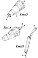
- the sleeve can then be folded flat and placed in a box for transport and later use. It will be noted that the triangular points of the release paper extended beyond the narrow opening in the top of the sleeve (Fig.5).
- the operator After removal of the sleeve from storage the operator has a simple task of folding the exposed and protruding triangular flaps projecting from the narrow open end of the sleeve, such that the ends return through the open hole (Fig.6). The then represented ends of the triangles are grasped separately or together and pulled back through the inside of the cone sleeve form (Fig.7). This is easily accomplished, in a controlled manner even by an inexperienced person. The sleeve may then be fitted to a cone body. It is to be understood that the assembly can be constructed such that the release paper pieces can only be removed separately, can only be removed together or can be optionally removed separately or together.
- the above described specific embodiment uses three pieces of release paper. While this was found particularly useful, the principle of providing one or more extensions to the release paper such that it can be returned inside the cone sleeve to facilitate removal works with a single piece or more than one piece of release paper and thus, a single piece suitably formed is within the scope of the present invention.
- the extensions of the pieces of release paper to a triangular point can have any shape and may be of another material, possibly stronger than the release paper.
- Such an extension might take the form of a string, ribbon, tape or strip or other means which can perform substantially in the same function.
- an extension of the release paper which extends from either or both of the top and bottom opening of the preformed sleeve is not essential and other forms of extension for removal of the release paper can be used.
- a pull point can be provided at a corner or edge of a precisely fitting release paper, or a piece of the release paper within the sleeve may overlap another piece of release paper, the overlap acting as an extension by which the release paper can be removed.
- the release paper does not have to extend at both ends, but needs to be of sufficient area to substantially cover the adhesively coated inner surface of the sleeve to prevent adhesion of the internal surfaces of the sleeve during storage.
- a single sheet of release paper extending over an arc of 180° or more of the inside surface of the sleeve would suffice to keep the adhesive covered surfaces apart if the single piece of release paper is provided with a means of facilitating removal as above.
- the triangular shaped pieces of release paper utilised above are substituted by rectangular shapes, again with extension pieces attached to one end, but in this case, the extension pieces 24 being sufficiently long to pass far enough back down the tubular sleeve to be reached by the operative for removal.
- the strips should pass right through the sleeve from one end to the other to be visible and easily graspable.
- the extensions of the release papers can be decorated or formed to enhance the products utilising this invention, or provide information to the operator seeking to use them.
Landscapes
- Engineering & Computer Science (AREA)
- Architecture (AREA)
- Civil Engineering (AREA)
- Structural Engineering (AREA)
- Physics & Mathematics (AREA)
- Geometry (AREA)
- Adhesive Tapes (AREA)
Applications Claiming Priority (2)
| Application Number | Priority Date | Filing Date | Title |
|---|---|---|---|
| GB9402177 | 1994-02-04 | ||
| GB9402177A GB9402177D0 (en) | 1994-02-04 | 1994-02-04 | Preformed self-adhesive sleeves for traffic control devices |
Publications (2)
| Publication Number | Publication Date |
|---|---|
| EP0666375A2 true EP0666375A2 (de) | 1995-08-09 |
| EP0666375A3 EP0666375A3 (de) | 1995-10-04 |
Family
ID=10749889
Family Applications (1)
| Application Number | Title | Priority Date | Filing Date |
|---|---|---|---|
| EP95300610A Withdrawn EP0666375A3 (de) | 1994-02-04 | 1995-01-31 | Vorgeformte, selbstklebende Hülsen für Verkehrsleiteinrichtungen. |
Country Status (2)
| Country | Link |
|---|---|
| EP (1) | EP0666375A3 (de) |
| GB (2) | GB9402177D0 (de) |
Cited By (2)
| Publication number | Priority date | Publication date | Assignee | Title |
|---|---|---|---|---|
| WO1999024671A1 (en) * | 1997-11-12 | 1999-05-20 | Minnesota Mining And Manufacturing Company | Multicolored retroreflective banded sleeve for a traffic device and method of making |
| EP1026325A3 (de) * | 1999-02-08 | 2002-01-02 | Oshima & Associates, Inc. | Freistehendes Zylindrisches Warnzeichen |
Families Citing this family (4)
| Publication number | Priority date | Publication date | Assignee | Title |
|---|---|---|---|---|
| US6517664B1 (en) | 2000-01-10 | 2003-02-11 | Process Resources Corporation | Techniques for labeling of plastic, glass or metal containers or surfaces with polymeric labels |
| US6656319B1 (en) | 2000-10-25 | 2003-12-02 | 3M Innovative Properties Company | Fluid-activatable adhesive articles and methods |
| CN103395392A (zh) * | 2013-07-12 | 2013-11-20 | 太仓市豪阳汽车内饰件有限公司 | 一种货车用夜光警示装置 |
| US20240384480A1 (en) * | 2023-05-18 | 2024-11-21 | Dwight Sanderson | Reflector Device |
Family Cites Families (4)
| Publication number | Priority date | Publication date | Assignee | Title |
|---|---|---|---|---|
| US3192889A (en) * | 1962-08-16 | 1965-07-06 | Cleveland B Crudgington | Road marker |
| GB2139116B (en) * | 1980-10-17 | 1985-08-29 | Minnesota Mining & Mfg | Portable road markers |
| US5236751A (en) * | 1991-03-28 | 1993-08-17 | Reflexite Corporation | Cone collars with temporary release coating and method for making and assembling same |
| GB2263299A (en) * | 1992-01-20 | 1993-07-21 | Brian Tregellis | Disposable traffic cone cover |
-
1994
- 1994-02-04 GB GB9402177A patent/GB9402177D0/en active Pending
-
1995
- 1995-01-31 EP EP95300610A patent/EP0666375A3/de not_active Withdrawn
- 1995-01-31 GB GB9501996A patent/GB2286781B/en not_active Expired - Fee Related
Cited By (2)
| Publication number | Priority date | Publication date | Assignee | Title |
|---|---|---|---|---|
| WO1999024671A1 (en) * | 1997-11-12 | 1999-05-20 | Minnesota Mining And Manufacturing Company | Multicolored retroreflective banded sleeve for a traffic device and method of making |
| EP1026325A3 (de) * | 1999-02-08 | 2002-01-02 | Oshima & Associates, Inc. | Freistehendes Zylindrisches Warnzeichen |
Also Published As
| Publication number | Publication date |
|---|---|
| GB2286781A (en) | 1995-08-30 |
| GB2286781B (en) | 1997-10-08 |
| EP0666375A3 (de) | 1995-10-04 |
| GB9402177D0 (en) | 1994-03-30 |
| GB9501996D0 (en) | 1995-03-22 |
Similar Documents
| Publication | Publication Date | Title |
|---|---|---|
| CA2061756C (en) | Folded leaflet label | |
| US3322325A (en) | Bag seal utilizing pressure sensitive tape having weakened transverse zones | |
| US5388300A (en) | Adhesive tape roll | |
| US5069969A (en) | Pressure sensitive adhesive tape with central release liner | |
| KR930005803Y1 (ko) | 팽창수축 재료 | |
| JP4156515B2 (ja) | 屋根をライニングするプラスチック箔を貫通する構造ユニットの通路を封止するための自己粘着封止テープ | |
| US5222766A (en) | Labels and manufacture thereof | |
| US3813180A (en) | Frangible concrete-joint sealant package | |
| CA2123009A1 (en) | Labels and manufacture thereof | |
| EP0666375A2 (de) | Vorgeformte, selbstklebende Hülsen für Verkehrsleiteinrichtungen | |
| NZ209656A (en) | Plastic label and attachment to bottle | |
| US4704315A (en) | Composite pressure sensitive seal adhesive construction | |
| US2446422A (en) | Container | |
| US6117262A (en) | Method of sealing a package | |
| US5286111A (en) | Bag ties and manufacture thereof | |
| US6183016B1 (en) | Labeling insulation tape | |
| AU710250B2 (en) | Wound roll and closure strip assembly | |
| US20220363950A1 (en) | Adhesive tape strip with end locator | |
| EP0659939A1 (de) | Vorgeformte Klebereflexionshülse für kegelförmige Verkehrszeichen | |
| US20060285919A1 (en) | Disposable cover for bumper blocks | |
| USRE29377E (en) | Frangible concrete-joint sealant package | |
| WO2003048262A2 (en) | Combination closure and tear tape, packaging materials containing it, and method of using it to seal and later open packages | |
| JPH0440256B2 (de) | ||
| CA1216225A (en) | Window shade and roller with manual severing means | |
| JP3456800B2 (ja) | シールラベルおよびシールラベル連続体 |
Legal Events
| Date | Code | Title | Description |
|---|---|---|---|
| PUAI | Public reference made under article 153(3) epc to a published international application that has entered the european phase |
Free format text: ORIGINAL CODE: 0009012 |
|
| AK | Designated contracting states |
Kind code of ref document: A2 Designated state(s): BE DE DK ES FR LU NL |
|
| PUAL | Search report despatched |
Free format text: ORIGINAL CODE: 0009013 |
|
| AK | Designated contracting states |
Kind code of ref document: A3 Designated state(s): BE DE DK ES FR LU NL |
|
| 17P | Request for examination filed |
Effective date: 19960328 |
|
| 17Q | First examination report despatched |
Effective date: 19970610 |
|
| GRAG | Despatch of communication of intention to grant |
Free format text: ORIGINAL CODE: EPIDOS AGRA |
|
| GRAG | Despatch of communication of intention to grant |
Free format text: ORIGINAL CODE: EPIDOS AGRA |
|
| GRAH | Despatch of communication of intention to grant a patent |
Free format text: ORIGINAL CODE: EPIDOS IGRA |
|
| STAA | Information on the status of an ep patent application or granted ep patent |
Free format text: STATUS: THE APPLICATION IS DEEMED TO BE WITHDRAWN |
|
| 18D | Application deemed to be withdrawn |
Effective date: 19980707 |