EP0666436A1 - Dispositif de commande pour boîte de vitesses - Google Patents
Dispositif de commande pour boîte de vitesses Download PDFInfo
- Publication number
- EP0666436A1 EP0666436A1 EP95100797A EP95100797A EP0666436A1 EP 0666436 A1 EP0666436 A1 EP 0666436A1 EP 95100797 A EP95100797 A EP 95100797A EP 95100797 A EP95100797 A EP 95100797A EP 0666436 A1 EP0666436 A1 EP 0666436A1
- Authority
- EP
- European Patent Office
- Prior art keywords
- actuating
- lever
- movement
- coupling element
- bearing
- Prior art date
- Legal status (The legal status is an assumption and is not a legal conclusion. Google has not performed a legal analysis and makes no representation as to the accuracy of the status listed.)
- Withdrawn
Links
- 230000008878 coupling Effects 0.000 claims abstract description 83
- 238000010168 coupling process Methods 0.000 claims abstract description 83
- 238000005859 coupling reaction Methods 0.000 claims abstract description 83
- 230000007246 mechanism Effects 0.000 claims abstract description 11
- 230000005540 biological transmission Effects 0.000 claims description 76
- 238000006073 displacement reaction Methods 0.000 claims description 21
- 230000008859 change Effects 0.000 claims description 4
- 210000000056 organ Anatomy 0.000 claims description 2
- 230000007935 neutral effect Effects 0.000 abstract description 3
- 230000000903 blocking effect Effects 0.000 description 12
- 230000006835 compression Effects 0.000 description 2
- 238000007906 compression Methods 0.000 description 2
- 238000000034 method Methods 0.000 description 2
- 230000008569 process Effects 0.000 description 2
- 230000001960 triggered effect Effects 0.000 description 2
- 230000009471 action Effects 0.000 description 1
- 238000005452 bending Methods 0.000 description 1
- 230000008901 benefit Effects 0.000 description 1
- 230000000694 effects Effects 0.000 description 1
- 238000009434 installation Methods 0.000 description 1
- 239000002184 metal Substances 0.000 description 1
Images


Classifications
-
- F—MECHANICAL ENGINEERING; LIGHTING; HEATING; WEAPONS; BLASTING
- F16—ENGINEERING ELEMENTS AND UNITS; GENERAL MEASURES FOR PRODUCING AND MAINTAINING EFFECTIVE FUNCTIONING OF MACHINES OR INSTALLATIONS; THERMAL INSULATION IN GENERAL
- F16H—GEARING
- F16H61/00—Control functions within control units of change-speed- or reversing-gearings for conveying rotary motion ; Control of exclusively fluid gearing, friction gearing, gearings with endless flexible members or other particular types of gearing
- F16H61/26—Generation or transmission of movements for final actuating mechanisms
- F16H61/36—Generation or transmission of movements for final actuating mechanisms with at least one movement being transmitted by a cable
Definitions
- the invention relates to an actuating device, in particular a switching device for change gearboxes, with a transmission mechanism which is provided on one end with an actuating lever, in particular a shift lever, and on the other hand with a coupling element for connection to an organ to be actuated, in particular a gear linkage, the actuating lever being provided in a first Direction is movable in several operating levels and pivotable in each operating level in a second direction and the movements of the operating lever in both directions can be transmitted to the coupling element with the aid of the transmission mechanism in such a way that it can also be moved in two directions.
- the non-automatic change gears in vehicles are usually operated with the help of a shift lever located next to the driver's seat.
- the shift lever In the neutral position, i.e. when the gear is not shifted, the shift lever can be moved sideways, i.e. H. be swiveled transversely in the selection direction in order to reach at least two switching levels. The shift lever can then be moved forwards or backwards in each shifting level in order to carry out a shifting operation.
- the movements of the shift lever both in the selection direction and in the switching direction are transmitted to a coupling element with the aid of a transmission mechanism.
- This sits displaceably and rotatably on one in the gear entering gear linkage.
- the connection of the transmission mechanism with the shift lever and the coupling element is designed so that a movement of the shift lever in the switching direction leads to a pivoting of the coupling element and thus to a rotation of the transmission linkage, while a movement of the shift lever in the selection direction results in a movement of the coupling element and thus the transmission linkage in its axial direction.
- the transmission mechanism consists of a transmission linkage.
- a transmission linkage allows an exact transmission of the movement of the shift lever to the coupling element.
- the assembly and adjustment of a transmission linkage is complex.
- the invention is therefore based on the object to design an actuating device of the type mentioned so that it is as simple as possible and can be assembled and that a transmission of the movement z. B. a transmission is still prevented.
- the transmission mechanism has an actuating cable with an actuating core and an actuating jacket surrounding it as actuating members and that the actuating lever and the coupling element are connected to at least one of the actuating members in such a way that with the movement of the actuating lever in one direction Sliding movement of at least one actuator and thus a movement of the coupling element in one direction and that with the movement of the actuating lever in its other direction, a twisting movement of at least one actuating member and thus a movement of the coupling element in its other direction can be effected.
- wire pulls which have a flexible actuating jacket and an actuating wire guided axially therein can be considered as actuating cables.
- the basic idea of the invention is to use an actuating cable as the transmission mechanism, which is used both for the transmission of tension and pressure and for the transmission of torsional force. It has been shown that such a combined power transmission with actuating cables despite their flexibility with a z. B. can be used for a gear shift sufficiently precise function. Such actuation cables have the advantage that movements such. B. a transmission due to their flexibility can not be transferred to the shift lever and that they do not require adjustment with regard to the arrangement of the transmission and shift lever. In addition, such actuating cables are easier and faster to assemble and replace.
- the actuating lever and the coupling element are connected to both actuators in such a way that with the movement of the actuating lever in one direction a displacement movement of at least one actuator and thus a movement of the coupling element in one direction and that with the movement of the actuating lever in its other direction, a rotational movement of at least the other actuator and thus a movement of the coupling element in its other direction can be effected.
- the power transmission is divided between the two actuators. This makes it possible to specifically adapt at least one of the actuators to the type of force transmitted by it.
- each actuator has only one type of force - be it tension and pressure or torsion - to be transmitted, so that the actuators can be specially adapted to the respective type of power transmission.
- the actuating lever and the coupling element are connected to the actuators in such a way that with the movement of the actuating lever in one direction a displacement movement of the one Actuator and thus a movement of the coupling element in one direction and that with the movement of the actuating lever in its other direction, a twisting movement of both actuators and thus a movement of the coupling element in its other direction can be effected.
- both actuators are used to transmit torsional forces, which increases the torsional rigidity.
- both actuators can be effected for the transmission of the displacement movement and one of the actuators can be effected for the transmission of the rotational movement by a corresponding connection of the actuating lever and coupling element to the actuators.
- the actuating core is primarily suitable for the transmission of the displacement movement, since it is guided in the actuating jacket over the entire distance. This does not exclude that the actuating jacket is also used for this. However, this should preferably be used for the transmission of the twisting movement.
- the actuating jacket is also primarily suitable for the combined transmission of twisting and shifting movements.
- the movable actuating member or the movable actuating members are connected to the coupling element in such a way that with the displacement movement the coupling element can be pivoted about an axis and with the twisting movement the coupling element can be displaced along this axis is.
- the actuating lever can be pivoted about an axis running in one direction in a bearing element and this bearing element can be pivoted in a lever holder about one running in the other direction Swivel axis is mounted.
- the actuating cable should be coaxial to the pivot axis of the bearing element and the actuating element or actuators for the transmission of the rotational movement should be connected to the bearing element in a rotationally fixed manner.
- simple storage can be produced in that the actuating jacket has a rigid bearing sleeve on the switching lever side, via which the bearing element is mounted in the lever holder. In this way, the actuating jacket itself forms the bearing in the lever holder.
- the lever holder expediently has a U-shape with upstanding U-legs on both sides, in which the bearing element is mounted. This can also have a U-shape with upstanding U-legs on both sides, via which the bearing element is then mounted on the lever holder.
- the coupling element has a pivot lever to which the actuating member performing the displacement movement is attached and which is pivotably mounted about an axis directed transversely to the pivot axis of the coupling element. This storage avoids bending and tension when the coupling element moves in the direction of its pivot axis.
- the actuating element (s) executing the twisting movement is or are connected on the coupling element side to a transmission lever which interacts with the coupling element.
- the transmission lever should be positively connected to the coupling element in such a way that the coupling element is carried along in the direction of movement of the transmission lever, but a pivoting movement of the coupling element about its pivot axis is not impeded.
- the connection of the coupling element and the transmission lever can be designed as a fork on one side and a sliding piece encompassing the fork on the other side.
- the transmission lever should be divided into a lever section on the coupling element side and a lever section on the actuating cable side, the lever sections being mutually adjustable in the direction of movement of the transmission lever.
- a pull bracket is provided on the coupling element side, in which the actuating jacket is mounted.
- the actuating jacket can have a rigid bearing sleeve at the end, by means of which it is mounted in the pull bracket.
- the transmission lever can then be fastened in a rotationally fixed manner to the bearing sleeve when the actuating jacket is used for the torsional force transmission.
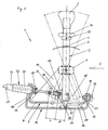
- the shift lever arrangement (1) shown in FIGS. (1) and (2) has a straight, tubular shift lever (2) standing vertically in the position shown, which has a shift button (3) on the top. In the upper third, it has an annular groove (4) into which a flexible sleeve (5) surrounds, which covers the lower part of the shift lever arrangement after installation in a vehicle.
- the shift lever (2) is surrounded by a bearing sleeve (6) with which it is welded.
- the shift lever (2) is mounted in a bearing rocker (7) about a horizontal axis in the switching direction via this bearing sleeve (6).
- the bearing rocker (7) has a horizontal rocker base (8), from the long sides of which two bearing legs (9, 10 ⁇ ) stand up, one of which is cut away in Figure (1).
- the bearing legs (9, 10 ⁇ ) include the bearing sleeve (6) in the upper region.
- the bearing legs (9, 10 ⁇ ) each engage from the outer sides, bearing screws (11, 12) which are screwed into the bearing sleeve (6) and allow the switching lever (2) to be pivoted in the drawing plane of FIG. (1).
- the bearing rocker (7) also has bent-up bearing arms (13, 14) on the transverse sides.
- the bearing rocker (7) can be pivoted about a pivot axis (15) in a gear lever bracket (16) by means of these bearing arms (13, 14).
- the shift lever bracket (16) has a horizontal bracket base (17), from the transverse sides of which bearing legs (18, 19) stand up, which run parallel and in each case on the outside to the bearing legs (13, 14) of the rocker (7).
- the bearing leg (19) on the right in FIG. (1) of the shift lever bracket (16) and the adjacent bearing leg (10 ⁇ ) of the rocker (7) includes a bearing screw (20 ⁇ ), which is held by a nut (21) and allows pivoting of the rocker (7) about the pivot axis (15).
- a metallic bearing sleeve (25) is slipped over the end of the wire pull sheath (23), which is pulled through by the wire strand (24) and is connected in a rotationally fixed manner to the wire pull sheath (23).
- the bearing sleeve (25) has a circular cross section in the area in which it penetrates the bearing arm (18) of the gear lever bracket (16) and is rotatably supported there.
- the bearing sleeve (25) has a shoulder and is polygonal there, whereby it is form-fitting, i.e. rotatably encloses in a correspondingly designed opening in the bearing leg (9) of the rocker (7).
- the bearing sleeve (25) is held immovably in the longitudinal direction by a clip (26). Due to the bearing function of the bearing sleeve (25), a pivot axis (15) is formed which is coaxial to the longitudinal axis of the wire pull (22).
- the wire strand (24) extends to the lower end of the shift lever (2) and ends there in a fork (27).
- This comprises a connecting plate (28) which is welded to the shift lever (2) and has an elongated hole (29) through which a hinge pin (30 ⁇ ) passes, which extends between the two fork legs of the fork (27).
- the shift lever (2) is pivotally connected to the wire strand (24), the elongated hole (29) ensuring that the wire strand (24) is not bent into the two positions shown in broken lines when the shift lever (2) is shifted .
- a blocking pin (31) runs on the inside and coaxially to the longitudinal axis of the shift lever (2) and is pressed down with the aid of a compression spring (32) on the top.
- the upper end of the blocking pin (31) is connected via a cross pin (33) to an actuating ring (34) which surrounds the switching lever (2) on the outside and via which the blocking pin (31) can be raised against the action of the compression spring (32) .
- the blocking pin (31) protrudes in the non-raised state to close to the console base (17) beyond the end of the shift lever (2) and penetrates a bottom slot (35) in the rocker base (8).
- the bottom slot (35) ensures that the shift lever (2) remains freely pivotable about the axis of the bearing sleeve (6) even with the blocking pin (31) projecting from below.
- a blocking strip (36) is welded onto the console base (17), which prevents the switching lever (2) from pivoting transversely about the pivot axis (15) when the blocking pin (31) is in the non-raised position, as shown in FIGS. (1) and (2) show.
- the shift lever (2) is in a central plane (37).
- the switching movement of the shift lever (2) counterclockwise (FIG. 1) exerts a tensile load on the wire strand (24) and, as will be explained further below, the first gear is shifted.
- the shift lever (2) is turned in the opposite direction, ie swiveled clockwise, a pressure force is exerted on the wire strand (24) and the second gear is shifted in this way.
- the displacement movements of the wire strand (24) are represented by the double arrows A and A '. If the shift lever (2) is pivoted from the position shown into an outer plane (38) by a selection movement, the bearing rocker (7) also rotates about the pivot axis (15).
- a transverse pivoting of the shift lever (2) from the outer plane (38) is normally only possible up to the middle plane (37) because of the blocking pin (31) and the blocking strip (36).
- the blocking pin (31) In order to be able to also switch into reverse gear, the blocking pin (31) must be raised so far with the aid of the actuating ring (34) that its end comes to rest above the blocking strip (36).
- the shift lever (2) can then be swiveled transversely into the reverse gear plane (39) and then pivoted longitudinally counterclockwise, the pulling movement thereby transmitted to the stranded wire (24) causing the reverse gear to be switched.
- the shift lever (2) If the shift lever (2) is then brought back into the idling plane, it can be pivoted in this plane back into the middle plane (37) or even into the outer plane (38), the blocking pin (31) - when the actuating ring (34) is released is - automatically jumps back to the starting position shown, with the result that the reverse gear level (39) is locked again.
- the wire pull (22) also ends here in a rigid bearing sleeve (40 ⁇ ) into which the wire pull jacket (23) protrudes, the bearing sleeve (40 ⁇ ) and the wire pull jacket (23) being connected to one another in a rotationally fixed manner.
- the bearing sleeve (40 ⁇ ) is formed in a sheet metal part End bracket (41) rotatably mounted.
- the end bracket (41) has a vertical leg (42), on which a fastening tab (43) is integrally formed on the upper side.
- the vertical leg (42) and the fastening tab (43) have fastening holes (44, 45) through which the end bracket (41) can be fixed in place on a vehicle part with the aid of screws.
- the end bracket (41) has bearing legs (46, 47) at the front and rear.
- the bearing leg (46) on the left in FIG. (3) has a through hole in which the bearing sleeve (40 ⁇ ) is rotatably mounted.
- the other bearing leg (47) has a fork-shaped opening, into which the bearing sleeve (40 ⁇ ) is inserted and secured by a likewise inserted sleeve (48), within which the bearing sleeve (40 ⁇ ) can be rotated.
- a clip (49) is provided, which fits into a suitable groove within the bearing sleeve (40 ⁇ ).
- a transmission lever (50 ⁇ ) Fixed to the bearing sleeve (40 sich) is a transmission lever (50 ⁇ ) which extends essentially radially thereto and which is constructed in two parts.
- a first lever section (51) is welded to the outside of the bearing sleeve (40 ⁇ ).
- a second lever section (52) is rotatably mounted on the bearing sleeve (40 ⁇ ) and has a double-curved actuating arm (53), at the free end of which an actuating fork (54) is seated.
- the free, outer end of the first lever section (51) is fixedly connected to the second lever section (52) by means of a screw (55), so that a rotational movement of the bearing sleeve (40 ⁇ ) via the first lever section (51) onto the second lever section (52 ) and thus also transmitted to the actuating arm (53).
- the screw (55) passes through an arcuate slot (56), the arc of which has a radius which corresponds to the distance to the central axis of the bearing sleeve (40 ⁇ ). In this way, an adjustment of the two lever sections (51, 52) to each other in the circumferential direction and thus an initial position of the actuating fork (54) is possible.
- the actuating fork (54) acts on a coupling element (57).
- the coupling element (57) projects into the actuating fork (54) with an arc-shaped sliding piece (58).
- the coupling element (57) sits on a transmission input rod (59) and is fixed on it in a rotationally fixed and non-displaceable manner.
- the coupling element (57) On the underside, the coupling element (57) has two welded-on bearing rings (60 ⁇ , 61), which are penetrated by a bearing pin (62).
- a bearing sleeve (63) is freely rotatable on the bearing pin (62) between the bearing rings (60 ⁇ , 61).
- a swivel lever (64) is welded to its underside. At its free end, it has a vertical elongated hole (65).
- the pivot lever (64) is connected to the wire strand (24) of the wire pull (22) via a fork (65) attached to the end of the wire strand (24), which comprises the pivot lever (64).
- the connection is made by a fork pin (67) which passes through the slot (65) and is connected to the legs of the fork (66).
- the pivot lever (64) In the position shown in Figures (3) and (4), which corresponds to the position of the shift lever (2) in Figures (1) and (2), the pivot lever (64) is in a vertical position, namely the neutral or idle position. No gear is selected.
- the actuating arm (53) has a position with the actuating fork (54) which enables a switching operation in the first or second. As described above, this can be done by pivoting the shift lever in the central plane (37), ie by a shifting movement, as a result of which the wire strand (24) is shifted in the pulling direction for the first gear and in the pushing direction for the second gear.
- the shifting movement is transferred to the lever arm (64) accordingly, ie counterclockwise for the first gear and clockwise for the second gear, in each case by the indicated 17 °.
- the transmission input rod (59) is then in a position in which the reverse gear can be switched on. This is done by longitudinally pivoting the shift lever (2) counterclockwise with the result that a tensile force is exerted on the wire strand (24) which pivots the pivot lever (64) counterclockwise and thus the coupling element (57) and with it the transmission input rod (59) twisted in the same direction.
- the shift lever (2) is pivoted transversely into the outer plane (38) in the manner already described above. This pivoting leads to a twisting of the wire tension jacket (23) and thus the bearing sleeve (40 ⁇ ). This in turn pivots the transmission lever (50 ⁇ ) in a direction opposite to the direction when pivoting into the reverse gear plane (39) goes.
- the coupling element (57) and the transmission input rod (59) are shifted accordingly in the opposite direction and in this way reach a position in which the third or fourth gear can be shifted in the transmission.
- the switching process is then effected by longitudinally pivoting the shift lever (2) in the drawing plane according to FIG. (1), specifically for the third gear by longitudinally pivoting counterclockwise and consequently by exerting a pull on the wire strand (24) and thus pivoting the pivoting lever (64). counter clockwise.
- the shift lever (2) is moved clockwise with the result that pressure is exerted on the wire strand (24) and this is shifted in the direction of pressure application.
- the pivot lever (64) is then pivoted clockwise.
- Figure (6) shows the position then assumed in contrast to the positions according to Figures (4) and (5).
- the force transmission between the shift lever (3) and the coupling element (57) is divided in such a way that the wire tension jacket (23) absorbs the torsional forces alone and the wire tension (22) alone the tension and pressure forces.
- FIGS. (7) to (11) show different switching arrangements (71, 72, 73, 74, 75), in the following description the same or functionally identical parts are denoted by the same reference numerals.
- the switching arrangements (71, 72, 73, 73, 75) each have a U-shaped switching bracket (76) with bearing legs (77, 78) which are bent up vertically on their transverse sides.
- the bearing rocker (79) has on the transverse sides upstanding bearing legs (80 ⁇ , 81) which run parallel and adjacent to the bearing legs (77, 78) of the switching console (76).
- the bearings allow the rocker (90 ⁇ ) to pivot relative to the switching console (76) around the pivot axis (82).
- the bearing rockers (79) have upstanding, further bearing legs (83) on their long sides, of which the bearing leg lying at the front in the view is omitted here in order to enable the view in the space enclosed by the two bearing legs (83).
- an A-shift lever (84) is pivotably mounted in the longitudinal direction in a bearing (85) between the bearing legs (83).
- the swivel ranges are indicated by dot-dash lines.
- the axis of the bearing (85) is perpendicular to the plane of the drawing.
- a wire pull (86) comes from the left side in these views. It has a wire pull jacket (87) which is connected in a rotationally fixed manner to an end sleeve (88). From the free end of the end sleeve (88), a short piece of wire pull sheath (87) and a wire strand (89) emerge, which ends in an end eye (90 ⁇ ), which enables a twist-proof attachment.
- FIGS. (7) to (11) differ as follows.
- the end sleeve (88) - similarly to the exemplary embodiment according to FIGS. (1) and (2) - is rotatably mounted in the bearing leg (77) of the switching console (76), but non-rotatably with the bearing leg (80 ⁇ ) of the rocker (79) connected.
- This has the consequence that when the switching lever (84) is pivoted transversely in the direction of selection for the purpose of changing the switching plane, the pivoting movement of the rocker arm (79) triggered by this is triggered Swivel axis (82) is transferred to the wire tension jacket (87).
- the wire strand (89) is articulated in a rotationally fixed manner on the shift lever (84) via the end eye (90 ⁇ ).
- a transverse pivoting of the shift lever (84) therefore also results in a twisting of the wire strand (89).
- the change in a switching level leads in this way to a twisting movement of both the wire tension jacket (87) and the wire strand (89).
- the wire strand (89) should also have an operating lever at the end there, which interacts with the transmission lever (50 ⁇ ) in such a way that the force transmitted by the wire strand (89) is also passed on to the coupling element (57).
- the switching lever (84) is pivoted longitudinally in the plane of the drawing, as indicated by dash-dotted lines.
- tensile or compressive forces are transmitted to the stranded wire (89), which result in a corresponding displacement movement.
- the wire strand (89) has a double function, since it is intended both for the transmission of tensile and compressive forces and for the transmission of torsional forces.
- the switching console (76) has an extension (91) with a bent-up holding leg (92), in which the end sleeve (88) is held in a rotationally fixed manner.
- the wire strand (89) penetrates the bearing leg (77) of the switching console (76) and the bearing leg (80 ⁇ ) of the rocker (79) and is connected in a rotationally fixed manner to the switching lever (84) via the end eye (90 ⁇ ).
- the wire strand (89) is intended for the transmission of all movements, ie it is shifted in the longitudinal direction when a gear is switched on and when one is changed Switching level twisted. So that the latter is transmitted to the coupling element (57), the end of the wire strand (89) there would have to be connected to the transmission lever (50 ⁇ ).
- the transmission lever (50 ⁇ ) must then not be fixed to the bearing sleeve (40 ⁇ ) there.
- the wire tension jacket (87) has only the function of a guide in this embodiment and is therefore not used for power transmission.
- the wire pull (86) penetrates the left-hand bearing arm (77) of the switching console (76) and also the bearing arm (80 ⁇ ) of the rocker (79) there. Its end sleeve (88) projects into the space between the two bearing legs (83) of the bearing rocker (79).
- the wire strand (89) is attached with its end eye (90 ⁇ ) rotatably to the two bearing legs (83) of the rocker (79). If the switching lever (84) is pivoted in the transverse direction for the purpose of changing a switching level, this has the consequence that the pivoting movement is transmitted to the wire strand (89) via the bearing rocker (79). At the other end, the wire strand (89) would then have to be connected to the transmission lever (50 ⁇ ) so that the twisting movement is transmitted to the coupling element (57).
- the power transmission compared to the embodiment shown in Figures (1) and (2) interchanged, because the wire tension sheath (87) is used only for tension-pressure transmission and the wire strand (89) only for torsion transmission.
- the exemplary embodiment according to FIG. (10 ⁇ ) differs from that according to FIG. (9) only in that the shift lever fork (93) is rotatably coupled to the end sleeve (88).
- the wire tension sheath (87) not only serves to transmit tensile and compressive forces, but is also twisted together with the wire strand (89) when the gear level is changed. The torsional movement is thus transmitted to both parts of the wire pull (86), while the displacement movement is carried out only by the wire pull jacket (87).
- the shift lever (84) has a shift lever fork (93), which is connected to the end sleeve (88) of the wire pull jacket (87) so that it is fixed in terms of rotation and displacement.
- the switching console (76) has an extension (94) on the right-hand side with a raised support leg (95). In this the end eye (90 der) of the wire strand (89) is held against rotation and displacement. In this case, the stranded wire (89) only serves to guide the wire pull casing (87), which is axially displaced during a switching operation and rotated when the switching level is changed.
- the wire pull casing (87) must be connected at the other end on the one hand to the pivot lever (64) and on the other hand to the transmission lever (50 ⁇ ) in such a way that the coupling element (57) with the transmission input rod is moved by a displacement movement of the pivot lever (64) and by a twisting movement (59) can be moved.
Landscapes
- Engineering & Computer Science (AREA)
- General Engineering & Computer Science (AREA)
- Mechanical Engineering (AREA)
- Gear-Shifting Mechanisms (AREA)
- Arrangement Or Mounting Of Control Devices For Change-Speed Gearing (AREA)
- Valve Device For Special Equipments (AREA)
- Valve-Gear Or Valve Arrangements (AREA)
Applications Claiming Priority (2)
| Application Number | Priority Date | Filing Date | Title |
|---|---|---|---|
| DE9401671U DE9401671U1 (de) | 1994-02-02 | 1994-02-02 | Betätigungseinrichtung insbesondere für Wechselgetriebe |
| DE9401671U | 1994-02-02 |
Publications (1)
| Publication Number | Publication Date |
|---|---|
| EP0666436A1 true EP0666436A1 (fr) | 1995-08-09 |
Family
ID=6904008
Family Applications (1)
| Application Number | Title | Priority Date | Filing Date |
|---|---|---|---|
| EP95100797A Withdrawn EP0666436A1 (fr) | 1994-02-02 | 1995-01-21 | Dispositif de commande pour boîte de vitesses |
Country Status (2)
| Country | Link |
|---|---|
| EP (1) | EP0666436A1 (fr) |
| DE (1) | DE9401671U1 (fr) |
Cited By (2)
| Publication number | Priority date | Publication date | Assignee | Title |
|---|---|---|---|---|
| DE19546813A1 (de) * | 1995-12-15 | 1997-06-19 | Kuester & Co Gmbh | Nehmer, insbesondere Getriebeanschluß für Kraftfahrzeuggetriebe |
| FR2856961A1 (fr) * | 2003-07-04 | 2005-01-07 | Renault Sa | Dispositif de commande externe de boite de vitesses pour planche de bord de vehicule |
Families Citing this family (1)
| Publication number | Priority date | Publication date | Assignee | Title |
|---|---|---|---|---|
| DE102011002762A1 (de) * | 2011-01-17 | 2012-07-19 | Bayerische Motoren Werke Aktiengesellschaft | Schaltstrang für eine Einstrangschaltvorrichtung |
Citations (7)
| Publication number | Priority date | Publication date | Assignee | Title |
|---|---|---|---|---|
| FR2215044A5 (fr) * | 1973-01-22 | 1974-08-19 | Chrysler France | |
| FR2566342A1 (fr) * | 1984-06-20 | 1985-12-27 | Alfa Romeo Auto Spa | Dispositif pour la commande manuelle de la boite de vitesses d'un vehicule automobile |
| JPS61180050A (ja) * | 1985-02-06 | 1986-08-12 | Isuzu Motors Ltd | 変速機の遠隔操作機構 |
| JPS61199118A (ja) * | 1985-02-28 | 1986-09-03 | Isuzu Motors Ltd | 変速機の遠隔操作機構 |
| JPS62238120A (ja) * | 1986-04-07 | 1987-10-19 | Chuo Spring Co Ltd | コントロ−ルケ−ブル及びそのコントロ−ルケ−ブルを使用した自動車用変速機操作装置 |
| JPS63200218A (ja) * | 1987-02-16 | 1988-08-18 | Nippon Cable Syst Inc | 変速機の遠隔操作装置 |
| WO1994000703A1 (fr) * | 1992-06-29 | 1994-01-06 | Volkswagen Aktiengesellschaft | Cable sous gaine |
Family Cites Families (5)
| Publication number | Priority date | Publication date | Assignee | Title |
|---|---|---|---|---|
| US2188403A (en) * | 1936-10-24 | 1940-01-30 | Frank D Frisby | Variable speed transmission mechanism for automobiles and the like |
| DE722390C (de) * | 1936-12-17 | 1942-07-09 | Blohm & Voss | Trimmbetaetigungseinrichtung fuer Flugzeuge |
| FR1123247A (fr) * | 1955-03-04 | 1956-09-19 | Perfectionnements aux commandes des véhicules | |
| GB1063875A (en) * | 1962-11-08 | 1967-03-30 | Humber Ltd | Improvements in or relating to vehicle gear change mechanisms |
| IT1240139B (it) * | 1990-03-20 | 1993-11-27 | Fiat Auto Spa | Dispositivo di comando per un cambio di velocita' di un autoveiccolo |
-
1994
- 1994-02-02 DE DE9401671U patent/DE9401671U1/de not_active Expired - Lifetime
-
1995
- 1995-01-21 EP EP95100797A patent/EP0666436A1/fr not_active Withdrawn
Patent Citations (7)
| Publication number | Priority date | Publication date | Assignee | Title |
|---|---|---|---|---|
| FR2215044A5 (fr) * | 1973-01-22 | 1974-08-19 | Chrysler France | |
| FR2566342A1 (fr) * | 1984-06-20 | 1985-12-27 | Alfa Romeo Auto Spa | Dispositif pour la commande manuelle de la boite de vitesses d'un vehicule automobile |
| JPS61180050A (ja) * | 1985-02-06 | 1986-08-12 | Isuzu Motors Ltd | 変速機の遠隔操作機構 |
| JPS61199118A (ja) * | 1985-02-28 | 1986-09-03 | Isuzu Motors Ltd | 変速機の遠隔操作機構 |
| JPS62238120A (ja) * | 1986-04-07 | 1987-10-19 | Chuo Spring Co Ltd | コントロ−ルケ−ブル及びそのコントロ−ルケ−ブルを使用した自動車用変速機操作装置 |
| JPS63200218A (ja) * | 1987-02-16 | 1988-08-18 | Nippon Cable Syst Inc | 変速機の遠隔操作装置 |
| WO1994000703A1 (fr) * | 1992-06-29 | 1994-01-06 | Volkswagen Aktiengesellschaft | Cable sous gaine |
Non-Patent Citations (4)
| Title |
|---|
| PATENT ABSTRACTS OF JAPAN vol. 011, no. 001 (M - 550) 6 January 1987 (1987-01-06) * |
| PATENT ABSTRACTS OF JAPAN vol. 011, no. 029 (P - 540) 28 January 1987 (1987-01-28) * |
| PATENT ABSTRACTS OF JAPAN vol. 012, no. 109 (M - 682) 8 April 1988 (1988-04-08) * |
| PATENT ABSTRACTS OF JAPAN vol. 012, no. 488 (P - 803) 20 December 1988 (1988-12-20) * |
Cited By (2)
| Publication number | Priority date | Publication date | Assignee | Title |
|---|---|---|---|---|
| DE19546813A1 (de) * | 1995-12-15 | 1997-06-19 | Kuester & Co Gmbh | Nehmer, insbesondere Getriebeanschluß für Kraftfahrzeuggetriebe |
| FR2856961A1 (fr) * | 2003-07-04 | 2005-01-07 | Renault Sa | Dispositif de commande externe de boite de vitesses pour planche de bord de vehicule |
Also Published As
| Publication number | Publication date |
|---|---|
| DE9401671U1 (de) | 1994-03-17 |
Similar Documents
| Publication | Publication Date | Title |
|---|---|---|
| DE69700390T2 (de) | Fahrrad-Gangschaltungshebel | |
| DE2822766C2 (de) | Sitz mit einer Sitzfläche und mit einer dieser gegenüber verschwenkbaren Rückenlehne | |
| DE68908925T2 (de) | Fernbetätigungseinrichtung. | |
| DE19625854A1 (de) | Steuereinrichtung zur Betätigung des Getriebes von Motorfahrzeugen | |
| EP0825367B1 (fr) | Dispositif d'actionnement pour transmission véhiculaire | |
| DE3824296C2 (fr) | ||
| DE4221762A1 (de) | Schalthebellagerung | |
| DE2630181C3 (de) | Vorrichtung zum Schwenken eines in zwei rechtwinklig zueinander stehenden Ebenen schwenkbar gelagerten Gegenstandes | |
| EP1931553B1 (fr) | Colonne de direction pour vehicule automobile | |
| DE10019854A1 (de) | Manueller Hebelantrieb für Stellvorrichtungen an Sitzen, insbesondere an Kraftfahrzeugsitzen | |
| DE68919616T2 (de) | Schaltsperreneinheit eines Fahrzeuggetriebes. | |
| DE112005000235T5 (de) | Antriebsmechanismus | |
| EP0936384A1 (fr) | Dispositif d'actionnement d'une boíte de vitesses de véhicule | |
| DE3319950A1 (de) | Manuelle fernschaltvorrichtung | |
| DE69304213T2 (de) | Innere Schalteinheit von einem Gangschaltmechanismus | |
| EP0666436A1 (fr) | Dispositif de commande pour boîte de vitesses | |
| EP1956273B1 (fr) | Dispositif de passage doté d'un dispositif à ressort pour boîte de vitesses | |
| DE69801608T2 (de) | Vorrichtung zum Schalten eines Gangwechselgetriebes eines Kraftfahrzeuges | |
| DE3505586A1 (de) | Steuereinrichtung fuer eine kupplung und ein getriebe eines motorfahrzeugs | |
| DE4101010A1 (de) | Vorrichtung zur uebertragung einer steuer- oder schaltbewegung, insbesondere zum schalten eines kraftfahrzeuggetriebes | |
| DE19526995B4 (de) | Seilzugbetätigender Kraftfahrzeugschalthebel-Gelenkmechanismus | |
| DE2836733A1 (de) | Schaltgetriebe | |
| DE69113601T2 (de) | Schaltvorrichtung für ein handgeschaltetes getriebe. | |
| DE102008052377B4 (de) | Schalthebelanordnung | |
| DE4407540B4 (de) | Steuereinrichtung für ein Getriebe |
Legal Events
| Date | Code | Title | Description |
|---|---|---|---|
| PUAI | Public reference made under article 153(3) epc to a published international application that has entered the european phase |
Free format text: ORIGINAL CODE: 0009012 |
|
| AK | Designated contracting states |
Kind code of ref document: A1 Designated state(s): BE DE ES FR GB IT PT SE |
|
| 17P | Request for examination filed |
Effective date: 19951227 |
|
| 17Q | First examination report despatched |
Effective date: 19960201 |
|
| STAA | Information on the status of an ep patent application or granted ep patent |
Free format text: STATUS: THE APPLICATION IS DEEMED TO BE WITHDRAWN |
|
| 18D | Application deemed to be withdrawn |
Effective date: 19960813 |