EP0666484A1 - Méthode pour enregistrer et reproduire un modèle de rayonnement pénétrant - Google Patents
Méthode pour enregistrer et reproduire un modèle de rayonnement pénétrant Download PDFInfo
- Publication number
- EP0666484A1 EP0666484A1 EP94200311A EP94200311A EP0666484A1 EP 0666484 A1 EP0666484 A1 EP 0666484A1 EP 94200311 A EP94200311 A EP 94200311A EP 94200311 A EP94200311 A EP 94200311A EP 0666484 A1 EP0666484 A1 EP 0666484A1
- Authority
- EP
- European Patent Office
- Prior art keywords
- reflection hologram
- volume reflection
- angle
- stimulated emission
- emission light
- Prior art date
- Legal status (The legal status is an assumption and is not a legal conclusion. Google has not performed a legal analysis and makes no representation as to the accuracy of the status listed.)
- Withdrawn
Links
- 230000005855 radiation Effects 0.000 title claims description 18
- 238000000034 method Methods 0.000 title claims description 9
- 230000000149 penetrating effect Effects 0.000 title claims description 7
- OAICVXFJPJFONN-UHFFFAOYSA-N Phosphorus Chemical compound [P] OAICVXFJPJFONN-UHFFFAOYSA-N 0.000 claims abstract description 165
- 230000004936 stimulating effect Effects 0.000 claims abstract description 59
- 239000010410 layer Substances 0.000 claims description 121
- 239000000049 pigment Substances 0.000 claims description 8
- 239000000975 dye Substances 0.000 claims description 7
- 229910052751 metal Inorganic materials 0.000 claims description 7
- 239000002184 metal Substances 0.000 claims description 7
- 238000003860 storage Methods 0.000 claims description 6
- 239000000203 mixture Substances 0.000 claims description 5
- 239000011241 protective layer Substances 0.000 claims description 4
- 238000002834 transmittance Methods 0.000 claims description 4
- 239000012463 white pigment Substances 0.000 claims description 3
- XYFCBTPGUUZFHI-UHFFFAOYSA-N Phosphine Chemical compound P XYFCBTPGUUZFHI-UHFFFAOYSA-N 0.000 claims 1
- 230000005670 electromagnetic radiation Effects 0.000 claims 1
- 239000000463 material Substances 0.000 description 17
- 239000011230 binding agent Substances 0.000 description 15
- -1 silver halide Chemical class 0.000 description 14
- 239000002245 particle Substances 0.000 description 12
- 239000004332 silver Substances 0.000 description 11
- 229910052709 silver Inorganic materials 0.000 description 11
- 230000001427 coherent effect Effects 0.000 description 9
- 238000001093 holography Methods 0.000 description 7
- SOGAXMICEFXMKE-UHFFFAOYSA-N Butylmethacrylate Chemical compound CCCCOC(=O)C(C)=C SOGAXMICEFXMKE-UHFFFAOYSA-N 0.000 description 6
- 229910052693 Europium Inorganic materials 0.000 description 6
- 229910052771 Terbium Inorganic materials 0.000 description 5
- 229910052794 bromium Inorganic materials 0.000 description 5
- 229910052801 chlorine Inorganic materials 0.000 description 5
- 239000000460 chlorine Substances 0.000 description 5
- 229910052772 Samarium Inorganic materials 0.000 description 4
- 239000012790 adhesive layer Substances 0.000 description 4
- 238000004061 bleaching Methods 0.000 description 4
- 239000011248 coating agent Substances 0.000 description 4
- 238000000576 coating method Methods 0.000 description 4
- 229920001577 copolymer Chemical compound 0.000 description 4
- 238000011161 development Methods 0.000 description 4
- 230000003287 optical effect Effects 0.000 description 4
- 229920002284 Cellulose triacetate Polymers 0.000 description 3
- 229910052684 Cerium Inorganic materials 0.000 description 3
- 239000001828 Gelatine Substances 0.000 description 3
- 229910052689 Holmium Inorganic materials 0.000 description 3
- KFZMGEQAYNKOFK-UHFFFAOYSA-N Isopropanol Chemical compound CC(C)O KFZMGEQAYNKOFK-UHFFFAOYSA-N 0.000 description 3
- 229910052779 Neodymium Inorganic materials 0.000 description 3
- 229910052769 Ytterbium Inorganic materials 0.000 description 3
- NNLVGZFZQQXQNW-ADJNRHBOSA-N [(2r,3r,4s,5r,6s)-4,5-diacetyloxy-3-[(2s,3r,4s,5r,6r)-3,4,5-triacetyloxy-6-(acetyloxymethyl)oxan-2-yl]oxy-6-[(2r,3r,4s,5r,6s)-4,5,6-triacetyloxy-2-(acetyloxymethyl)oxan-3-yl]oxyoxan-2-yl]methyl acetate Chemical compound O([C@@H]1O[C@@H]([C@H]([C@H](OC(C)=O)[C@H]1OC(C)=O)O[C@H]1[C@@H]([C@@H](OC(C)=O)[C@H](OC(C)=O)[C@@H](COC(C)=O)O1)OC(C)=O)COC(=O)C)[C@@H]1[C@@H](COC(C)=O)O[C@@H](OC(C)=O)[C@H](OC(C)=O)[C@H]1OC(C)=O NNLVGZFZQQXQNW-ADJNRHBOSA-N 0.000 description 3
- 239000003795 chemical substances by application Substances 0.000 description 3
- 229920000159 gelatin Polymers 0.000 description 3
- 235000019322 gelatine Nutrition 0.000 description 3
- 238000004519 manufacturing process Methods 0.000 description 3
- 238000012856 packing Methods 0.000 description 3
- 229920000642 polymer Polymers 0.000 description 3
- 238000012545 processing Methods 0.000 description 3
- 239000011347 resin Substances 0.000 description 3
- 229920005989 resin Polymers 0.000 description 3
- 229940117958 vinyl acetate Drugs 0.000 description 3
- CIWBSHSKHKDKBQ-JLAZNSOCSA-N Ascorbic acid Chemical compound OC[C@H](O)[C@H]1OC(=O)C(O)=C1O CIWBSHSKHKDKBQ-JLAZNSOCSA-N 0.000 description 2
- WKBOTKDWSSQWDR-UHFFFAOYSA-N Bromine atom Chemical compound [Br] WKBOTKDWSSQWDR-UHFFFAOYSA-N 0.000 description 2
- KAKZBPTYRLMSJV-UHFFFAOYSA-N Butadiene Chemical compound C=CC=C KAKZBPTYRLMSJV-UHFFFAOYSA-N 0.000 description 2
- 102000004190 Enzymes Human genes 0.000 description 2
- 108090000790 Enzymes Proteins 0.000 description 2
- 229910052691 Erbium Inorganic materials 0.000 description 2
- LFQSCWFLJHTTHZ-UHFFFAOYSA-N Ethanol Chemical compound CCO LFQSCWFLJHTTHZ-UHFFFAOYSA-N 0.000 description 2
- 229910052688 Gadolinium Inorganic materials 0.000 description 2
- QIGBRXMKCJKVMJ-UHFFFAOYSA-N Hydroquinone Chemical compound OC1=CC=C(O)C=C1 QIGBRXMKCJKVMJ-UHFFFAOYSA-N 0.000 description 2
- BQCADISMDOOEFD-UHFFFAOYSA-N Silver Chemical compound [Ag] BQCADISMDOOEFD-UHFFFAOYSA-N 0.000 description 2
- PPBRXRYQALVLMV-UHFFFAOYSA-N Styrene Chemical compound C=CC1=CC=CC=C1 PPBRXRYQALVLMV-UHFFFAOYSA-N 0.000 description 2
- 229910052775 Thulium Inorganic materials 0.000 description 2
- GWEVSGVZZGPLCZ-UHFFFAOYSA-N Titan oxide Chemical compound O=[Ti]=O GWEVSGVZZGPLCZ-UHFFFAOYSA-N 0.000 description 2
- XTXRWKRVRITETP-UHFFFAOYSA-N Vinyl acetate Chemical compound CC(=O)OC=C XTXRWKRVRITETP-UHFFFAOYSA-N 0.000 description 2
- 238000002835 absorbance Methods 0.000 description 2
- 239000000853 adhesive Substances 0.000 description 2
- 229910052783 alkali metal Inorganic materials 0.000 description 2
- 150000001340 alkali metals Chemical class 0.000 description 2
- 229910052797 bismuth Inorganic materials 0.000 description 2
- 239000007844 bleaching agent Substances 0.000 description 2
- GDTBXPJZTBHREO-UHFFFAOYSA-N bromine Substances BrBr GDTBXPJZTBHREO-UHFFFAOYSA-N 0.000 description 2
- 229910052793 cadmium Inorganic materials 0.000 description 2
- 229910052791 calcium Inorganic materials 0.000 description 2
- 229920006217 cellulose acetate butyrate Polymers 0.000 description 2
- 238000006243 chemical reaction Methods 0.000 description 2
- 230000000052 comparative effect Effects 0.000 description 2
- 238000001514 detection method Methods 0.000 description 2
- 230000003292 diminished effect Effects 0.000 description 2
- 239000006185 dispersion Substances 0.000 description 2
- 229920001971 elastomer Polymers 0.000 description 2
- 239000000839 emulsion Substances 0.000 description 2
- 230000002708 enhancing effect Effects 0.000 description 2
- 239000000835 fiber Substances 0.000 description 2
- 238000003384 imaging method Methods 0.000 description 2
- 229910052740 iodine Inorganic materials 0.000 description 2
- 229910052749 magnesium Inorganic materials 0.000 description 2
- 229920000728 polyester Polymers 0.000 description 2
- 229920000139 polyethylene terephthalate Polymers 0.000 description 2
- 239000005020 polyethylene terephthalate Substances 0.000 description 2
- WQGWDDDVZFFDIG-UHFFFAOYSA-N pyrogallol Chemical compound OC1=CC=CC(O)=C1O WQGWDDDVZFFDIG-UHFFFAOYSA-N 0.000 description 2
- 239000005060 rubber Substances 0.000 description 2
- 230000000638 stimulation Effects 0.000 description 2
- 229910052712 strontium Inorganic materials 0.000 description 2
- 230000008961 swelling Effects 0.000 description 2
- 229920002725 thermoplastic elastomer Polymers 0.000 description 2
- XLYOFNOQVPJJNP-UHFFFAOYSA-N water Substances O XLYOFNOQVPJJNP-UHFFFAOYSA-N 0.000 description 2
- 229910052727 yttrium Inorganic materials 0.000 description 2
- 229910052725 zinc Inorganic materials 0.000 description 2
- YHYAHQFBEVTKNN-UHFFFAOYSA-N 1,1-dichloroethene;2-methylidenebutanedioic acid;2-methylprop-2-enoic acid Chemical compound ClC(Cl)=C.CC(=C)C(O)=O.OC(=O)CC(=C)C(O)=O YHYAHQFBEVTKNN-UHFFFAOYSA-N 0.000 description 1
- ZVNPWFOVUDMGRP-UHFFFAOYSA-N 4-methylaminophenol sulfate Chemical compound OS(O)(=O)=O.CNC1=CC=C(O)C=C1.CNC1=CC=C(O)C=C1 ZVNPWFOVUDMGRP-UHFFFAOYSA-N 0.000 description 1
- MYLBTCQBKAKUTJ-UHFFFAOYSA-N 7-methyl-6,8-bis(methylsulfanyl)pyrrolo[1,2-a]pyrazine Chemical compound C1=CN=CC2=C(SC)C(C)=C(SC)N21 MYLBTCQBKAKUTJ-UHFFFAOYSA-N 0.000 description 1
- 229920008347 Cellulose acetate propionate Polymers 0.000 description 1
- ZAMOUSCENKQFHK-UHFFFAOYSA-N Chlorine atom Chemical compound [Cl] ZAMOUSCENKQFHK-UHFFFAOYSA-N 0.000 description 1
- 229910052692 Dysprosium Inorganic materials 0.000 description 1
- IMROMDMJAWUWLK-UHFFFAOYSA-N Ethenol Chemical compound OC=C IMROMDMJAWUWLK-UHFFFAOYSA-N 0.000 description 1
- PXGOKWXKJXAPGV-UHFFFAOYSA-N Fluorine Chemical compound FF PXGOKWXKJXAPGV-UHFFFAOYSA-N 0.000 description 1
- 229920002633 Kraton (polymer) Polymers 0.000 description 1
- 229910052765 Lutetium Inorganic materials 0.000 description 1
- 239000004952 Polyamide Substances 0.000 description 1
- 239000004642 Polyimide Substances 0.000 description 1
- 229910052777 Praseodymium Inorganic materials 0.000 description 1
- 229910004369 ThO2 Inorganic materials 0.000 description 1
- BZHJMEDXRYGGRV-UHFFFAOYSA-N Vinyl chloride Chemical compound ClC=C BZHJMEDXRYGGRV-UHFFFAOYSA-N 0.000 description 1
- 238000010521 absorption reaction Methods 0.000 description 1
- 150000001252 acrylic acid derivatives Chemical class 0.000 description 1
- 239000000654 additive Substances 0.000 description 1
- 230000001070 adhesive effect Effects 0.000 description 1
- 238000005273 aeration Methods 0.000 description 1
- 239000004411 aluminium Substances 0.000 description 1
- 229910052782 aluminium Inorganic materials 0.000 description 1
- XAGFODPZIPBFFR-UHFFFAOYSA-N aluminium Chemical compound [Al] XAGFODPZIPBFFR-UHFFFAOYSA-N 0.000 description 1
- 229960005070 ascorbic acid Drugs 0.000 description 1
- 235000010323 ascorbic acid Nutrition 0.000 description 1
- 239000011668 ascorbic acid Substances 0.000 description 1
- 230000003190 augmentative effect Effects 0.000 description 1
- DQXBYHZEEUGOBF-UHFFFAOYSA-N but-3-enoic acid;ethene Chemical group C=C.OC(=O)CC=C DQXBYHZEEUGOBF-UHFFFAOYSA-N 0.000 description 1
- MVAUZYMUXCUOQI-UHFFFAOYSA-N butyl 2-methylprop-2-enoate;2-methylprop-2-enoic acid;styrene Chemical compound CC(=C)C(O)=O.C=CC1=CC=CC=C1.CCCCOC(=O)C(C)=C MVAUZYMUXCUOQI-UHFFFAOYSA-N 0.000 description 1
- HIZDLVPIKOYIOY-UHFFFAOYSA-N butyl prop-2-enoate;2-methylprop-2-enoic acid;styrene Chemical compound CC(=C)C(O)=O.C=CC1=CC=CC=C1.CCCCOC(=O)C=C HIZDLVPIKOYIOY-UHFFFAOYSA-N 0.000 description 1
- 238000003490 calendering Methods 0.000 description 1
- 239000006229 carbon black Substances 0.000 description 1
- 239000000470 constituent Substances 0.000 description 1
- 239000013078 crystal Substances 0.000 description 1
- 238000003618 dip coating Methods 0.000 description 1
- 238000007606 doctor blade method Methods 0.000 description 1
- 239000002019 doping agent Substances 0.000 description 1
- 238000001035 drying Methods 0.000 description 1
- 238000010894 electron beam technology Methods 0.000 description 1
- 230000008030 elimination Effects 0.000 description 1
- 238000003379 elimination reaction Methods 0.000 description 1
- GLVVKKSPKXTQRB-UHFFFAOYSA-N ethenyl dodecanoate Chemical compound CCCCCCCCCCCC(=O)OC=C GLVVKKSPKXTQRB-UHFFFAOYSA-N 0.000 description 1
- XPNLOZNCOBKRNJ-UHFFFAOYSA-N ethyl prop-2-enoate;methyl 2-methylprop-2-enoate Chemical compound CCOC(=O)C=C.COC(=O)C(C)=C XPNLOZNCOBKRNJ-UHFFFAOYSA-N 0.000 description 1
- 238000001704 evaporation Methods 0.000 description 1
- 230000008020 evaporation Effects 0.000 description 1
- 229910052731 fluorine Inorganic materials 0.000 description 1
- 239000011737 fluorine Substances 0.000 description 1
- 239000011521 glass Substances 0.000 description 1
- PNDPGZBMCMUPRI-UHFFFAOYSA-N iodine Chemical compound II PNDPGZBMCMUPRI-UHFFFAOYSA-N 0.000 description 1
- 230000005865 ionizing radiation Effects 0.000 description 1
- 238000010030 laminating Methods 0.000 description 1
- 229910052746 lanthanum Inorganic materials 0.000 description 1
- 229910052745 lead Inorganic materials 0.000 description 1
- 229910052748 manganese Inorganic materials 0.000 description 1
- 239000013307 optical fiber Substances 0.000 description 1
- 229920000620 organic polymer Polymers 0.000 description 1
- 239000000123 paper Substances 0.000 description 1
- 229920002120 photoresistant polymer Polymers 0.000 description 1
- 229920003229 poly(methyl methacrylate) Polymers 0.000 description 1
- 229920002647 polyamide Polymers 0.000 description 1
- 229920000515 polycarbonate Polymers 0.000 description 1
- 239000004417 polycarbonate Substances 0.000 description 1
- 229920006267 polyester film Polymers 0.000 description 1
- 229920000570 polyether Polymers 0.000 description 1
- 229920001721 polyimide Polymers 0.000 description 1
- 239000004926 polymethyl methacrylate Substances 0.000 description 1
- 229920000098 polyolefin Polymers 0.000 description 1
- 229920002689 polyvinyl acetate Polymers 0.000 description 1
- 239000011118 polyvinyl acetate Substances 0.000 description 1
- 229940075065 polyvinyl acetate Drugs 0.000 description 1
- 238000002360 preparation method Methods 0.000 description 1
- 238000003672 processing method Methods 0.000 description 1
- 239000011253 protective coating Substances 0.000 description 1
- 229940079877 pyrogallol Drugs 0.000 description 1
- 238000002601 radiography Methods 0.000 description 1
- 238000002310 reflectometry Methods 0.000 description 1
- 238000012552 review Methods 0.000 description 1
- 230000035945 sensitivity Effects 0.000 description 1
- 239000002904 solvent Substances 0.000 description 1
- 230000003595 spectral effect Effects 0.000 description 1
- 238000005507 spraying Methods 0.000 description 1
- 239000000126 substance Substances 0.000 description 1
- 239000000758 substrate Substances 0.000 description 1
- LSNNMFCWUKXFEE-UHFFFAOYSA-L sulfite Chemical compound [O-]S([O-])=O LSNNMFCWUKXFEE-UHFFFAOYSA-L 0.000 description 1
- 229910052716 thallium Inorganic materials 0.000 description 1
- 238000009210 therapy by ultrasound Methods 0.000 description 1
- ZCUFMDLYAMJYST-UHFFFAOYSA-N thorium dioxide Chemical compound O=[Th]=O ZCUFMDLYAMJYST-UHFFFAOYSA-N 0.000 description 1
- 239000004408 titanium dioxide Substances 0.000 description 1
- 238000012546 transfer Methods 0.000 description 1
- 238000004073 vulcanization Methods 0.000 description 1
Images



Classifications
-
- G—PHYSICS
- G01—MEASURING; TESTING
- G01T—MEASUREMENT OF NUCLEAR OR X-RADIATION
- G01T1/00—Measuring X-radiation, gamma radiation, corpuscular radiation, or cosmic radiation
- G01T1/16—Measuring radiation intensity
- G01T1/20—Measuring radiation intensity with scintillation detectors
- G01T1/2012—Measuring radiation intensity with scintillation detectors using stimulable phosphors, e.g. stimulable phosphor sheets
Definitions
- the present invention relates to a method for recording and reproducing a pattern of penetrating radiation.
- penetrating radiation which is high energy radiation also known as ionizing radiation belonging to the class of X-rays, gamma-rays and high-energy elementary particle radiation, e.g. beta-rays, electron beam or neutron radiation.
- penetrating radiation For the conversion of penetrating radiation into visible light and/or ultraviolet radiation luminescent substances, called phosphors, are used.
- an X-ray radiograph is obtained by X-rays transmitted imagewise through an object and converted into light of corresponding intensity in a so-called intensifying screen (X-ray conversion screen) wherein phosphor particles absorb the transmitted X-rays and convert them into visible light and/or ultraviolet radiation to which a photographic film is more sensitive than to the direct impact of X-rays.
- intensifying screen X-ray conversion screen
- the light emitted imagewise by said screen irradiates a contacting photographic silver halide emulsion layer film which after exposure is developed to form therein a silver image in conformity with the X-ray image.
- the basic constituents of such X-ray imaging system operating with a photostimulable storage phosphor are an imaging sensor containing said phosphor in particulate form normally in a plate or panel, which temporarily stores the X-ray energy pattern, a scanning laser beam for photostimulation, a photoelectronic light detector, detecting the light emitted (stimulated emission light) upon photostimulation, said light dectector providing analogue signals that are converted subsequently into digital time-series signals, normally a digital image processor which manipulates the image digitally, a signal recorder, e.g. magnetic disk or tape, and an image recorder for modulated light exposure of a photographic film or an electronic signal display unit, e.g. cathode-ray tube.
- an imaging sensor containing said phosphor in particulate form normally in a plate or panel, which temporarily stores the X-ray energy pattern, a scanning laser beam for photostimulation, a photoelectronic light detector, detecting the light emitted (stimulated emission
- An X-ray recording system be it a conventional system or a system based on photostimulable phosphor, needs to provide the diagnostician with clear, sharp images with as low as possible noise, i.e. the diagnostician wants images with high signal to noise ratio (SNR).
- SNR signal to noise ratio
- the light emitted by the photostimulable phosphor (stimulated emission light) upon stimulation diverges in all directions and accordingly, unless the collecting means for the stimulated emission light (usually comprising a light guiding means and a photodetector) has a very wide opening angle for collecting the stimulated emission light, a more or less large amount of said stimulated emission light is not collected by the photodectector.
- the amount of stimulated emission light that is collected by the collecting means constitutes the signal.
- the photodector comprised in the collecting means for stimulated emission light, emits (small) signals even when no stimulated emission light is collected, thus creating a signal that has no relation at all to the amount of stimulated emission light.
- This unwanted signal is called hereinafter inherent noise.
- Said collecting means is, however, not only sensitive to the stimulated emission light, but also to the stimulating light.
- the signal coming from the unwanted detection of reflected stimulating light is also a noise factor (called hereinafter external noise). It is important that said collecting means collect only the stimulated emission light in order to achieve a high SNR (signal to noise ratio).
- the external noise can be diminished, as disclosed in e.g. US-P 4,535,238, US-P 4,654,533, EP-A 532 800, by inserting a dichroic or holographic filter, which only transmits the stimulated emission light, before the collecting means for the stimulated emission light to prevent the reflected stimulating light from entering said collecting means.
- the most obvious way to enhance the SNR of the X-ray recording system, after the elimination of the external noise, is to increase the amount of stimulated emission light that is effectively collected by said collecting means.
- the collection of stimulated emission light by said collecting means can be enhanced in various ways, e.g. by adapting the geometry of the stimulated emission light collection, or by adapting the composition of the panel carrying the photostimulable phosphor.
- Examples of adapting the panel carrying the photostimulable phosphor to enhance the output of stimulated emission light can be found in e.g. FR 2,534,721 and US-P 4,368,390 where it is disclosed to have a support that is reflective for the stimulated emission light by adding a white pigment to said support (FR 2,534,721) or having a reflective metal layer between the support and the phosphor layer (US-P 4,368,390).
- Another way to enhance the amount of stimulated emission light that emerges from the phosphor plate is to add multilayer optical filters to the phophor plate to increase the efficiency of utilization of the stimulating light (US-P 4,931,642)
- said volume reflection hologram H1 is situated at a distance of said phosphor panel of at most 2 mm, more preferably at most 200 ⁇ m.
- volume reflection hologram H1 forms an integral part of said phosphor panel.
- a photostimulable phosphor panel comprising following layers in consecutive order (i) a support capable of absorbing stimulating light, (ii) a volume reflection hologram (H2) reflecting stimulated emission light entering said volume reflection hologram under any angle and transmitting stimulating light entering said volume reflection hologram under any angle, (iii) a stimulable phosphor layer, (iv) a volume reflection hologram H1 reflecting stimulated emission light entering said volume reflection hologram under any angle outside a restricted angle, determined by the angular aperture of light collecting means for stimulated emission light and transmitting stimulated emission light entering said volume reflection hologram under said predetermined restricted angel.
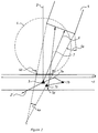
- Figure 1 is a simplified and magnified cross section, not on scale, through a photostimulable phosphor layer when no hologram according to the present invention is present and the stimulated emission light is captured by one detector.
- Figure 2 is the same as figure 1 except for the fact that a volume reflection hologram, H1, according to the present invention is present.
- Figure 3 is a simplified and magnified cross section, not on scale, through a photostimulable phosphor layer when said photostimulable phosphor is coated on a support capable of absorbing stimulating light and a volume reflection hologram, H1, according to the present invention is present on the surface of said photostimulable phosphor, facing the stimulating rays and a volume reflection hologram, H2, according to the present invention is interposed between said support and said photostimulable phosphor and the stimulated emission light is captured by one detector.
- Figure 4 is equal to figure 3 except for the fact that the stimulated emission light is captured by two detectors.
- Figure 5 is a simplified and magnified cross section, not on scale, through a photostimulable phosphor layer on a transparent support and a volume reflection hologram, H1, according to the present invention is present on the surface of said photostimulable phosphor, facing away from the stimulating rays and a volume reflection hologram, H2, according to the present invention is interposed between said transparent support and said photostimulable phosphor, while said support and volume reflection hologram H2 face the stimulating rays, and the stimulated emission light is captured by one detector.
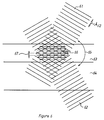
- Figure 6 illustrates, in a simplified and magnified way, a possible mode of producing a volume reflection hologram, H1, useful in the present invention.
- volume reflection hologram means a single volume reflection grating recorded in one sheet of recording material, or multiple volume reflection gratings recorded in one sheet of recording material, or a stack of two or more sheets of recording material, each having recorded therein a single or multiple volume reflection grating.
- FIG 1 the collection of stimulated emission light, when no volume reflection hologram, H1, according to the present invention is present is illustrated.
- a stimulating ray (2) impinges on a photostimulable phosphor layer (1), that previously had been exposed to a pattern of radiation
- a phosphor particle (3) emits the stored energy as stimulated emission light in all directions. Due to multiple scattering within the stimulable phosphor layer (1) any point on the surface of said photostimulable phosphor layer will emit light in all directions (i.e. as a sphere); i.e. each point behaves as a quasi Lambertian radiator. In the cross sectional view of figure 1 this sphere is visualized by circle (4) and extends above the surface of said photostimulable phosphor layer (1).
- FIG 2 the operation of a volume reflection hologram, herinafter called H1, according to the present invention, fixed on one side of a photostimulable phosphor layer is illustrated.
- the volume reflection hologram, H1, (8) is construed such as to be transparent for the stimulated emission light only within the angle (4a), which in connection with the angular aperture (5a) of said collecting means (5) is also the angle under which light collecting means (5) can collect the stimulated emission light, escaping from said photostimulable phosphor layer via surface 4b (i.e. the opening angle of said collecting means).
- Said volume reflection hologram, H1 has a transparency, preferably of at least 80 %, for the stimulating rays (2) entering said volume reflection hologram within angle 4a and is fixed on one side of the photostimulable phosphor layer (1), facing the stimulating rays and the light collecting means 5.
- a stimulating ray (2) impinges on a photostimulable phosphor layer (1), that previously had been exposed to a pattern of radiation, a phosphor particle (3) emits the stored energy as stimulated emission light in all directions, i.e. in a sphere.
- said stimulated emission light released by the phosphor particle (3) can only leave said stimulable phophor layer (1) within angle 4a, which in connection with the angular aperture (5a) of said collecting means (5) is also the predetermined restricted angle under which light collecting means (5) can collect said stimulated emission light (ray 6), escaping from said photostimulable phosphor layer via surface 4b.
- the ray, designated by 7 in figure 3, illustrates a possible fate of a photon of stimulated emission light that is reflected back in said photostimulable phosphor layer : ray 7 is reflected in point 7a by said volume reflection hologram, H1; on its way it encouters phosphor particle 7b and is deflected towards phosphor particle 7c, then it is deflected to the other side (bottom side) of said photostimulable phosphor layer; from said bottom side, in point 7d, it is reflected back into said photostimulable phosphor layer but now under such an angle that it reaches the interface between said photostimulable phophor layer and said volume reflection hologram H1 under an angle within angle 4a and is thus collected by said collecting means 5 for the stimulated emission light.
- the ray marked 2' in the figure 2 is that part of the stimulating ray 2 that escapes from the photostimulable phosphor layer 1
- the net result of having a volume reflection hologram, H1, according to the present invention fixed on one side of a photostimulable phosphor layer is that in the totality less stimulated emission light leaves said photostimulable phosphor layer, but that more stimulated emission light leaves said photostimulable phosphor layer under such an angle that it is collected by the collecting means for said stimulated emission light.
- FIG 3 the operation of a stimulable phosphor layer, comprising a volume reflection hologram, H1, as shown in figure 2, said phosphor layer being coated on a black support (10) and having a volume reflection hologram, H2, (9) interposed between said support and said stimulable phosphor layer, is shown.
- the volume reflection hologram, H2, (9) is construed so as to reflect, independently of the angle of incidence, preferably at least 80, more preferably at least 90 % of the stimulated emission light, arriving at the interface between said stimulable phosphor layer and said volume reflection hologram H2 and to transmit, independently of the angle of incidence, preferably at least 80, more preferably 90 % of the stimulating light arriving at the interface mentioned above.
- volume reflection hologram, H2 (9) enhances the reflection of stimulated emission light in point 7d in such a way that e.g. at least 80 % of said stimulated emission light is reflected back in said stimulable phosphor layer.
- both the amount of stimulated emission light that leaves said photostimulable phosphor layer under such an angle that it is collected by the collecting means for said stimulated emission light is enhanced and the possible external noise caused by the unwanted detection by said collector means of reflected stimulating light is diminished.
- a black support (10) a support that is capable of absorbing the wavelength of the stimulating light (2).
- a support (10) capable of absorbing the wavelength of the stimulating light (2) or in addition to said support it is possible, instead of having a support (10) capable of absorbing the wavelength of the stimulating light (2) or in addition to said support, to have the volume reflection hologram H2 (9) to absorb the wavelenght of stimulating light (2) by adding a suitable dye or pigment to said volume reflection hologram H2.
- Suitable dyes or pigment are e.g. those well known in the art of photography. Non limitative examples can be found in e.g. BE 835089, BE 850162, GB 393,844, US-P 3,594,171, US-P 4,923,788, EP-A 457153 etc.
- Figure 4 is analogous to figure 3, except for the presence of a second light collecting means 5' in a symmetrical position with respect to light collecting means 5.
- the volume reflection hologram H1 (8) is construed so a to be transparent both for the stimulated emission light entering said volume reflection hologram H1 (8) under both angle 4a, which in connection with the angular aperture 5a of the light collecting means 5 is the predetermined restricted angle under which light collecting means 5 can collect said stimulated emission light and angle 4'a, which in connection with the angular aperture 5'a of the light collecting means 5' is the predetermined restricted angle under which light collecting means 5' can collect said stimulated emission light.
- the light collecting means 5 and 5' can be the same or different. In figure 5, circle 4 is omitted, and the rays of stimulated emission light being captured by collecting means 5' are numbered 6' and 7' respectively.
- the stimulable phosphor layer and the volume reflection holograms H1 (8) and H2 (9) are applied to a support (10), which is transparent for the stimulating light.
- the stimulating rays (2) enter the stimulable phosphor layer from the side opposite to the position of the collecting means 5.
- the stimulating rays enter the assembly via volume reflection hologram H2 (9) .
- Said volume reflection hologram H2 (9) has again to be reflective for the stimulated emission light entering said volume reflection hologram H2 (9) under any angle and transparent for the stimulating light entering said volume reflection hologram H2 (9) under any angle.
- Volume reflection hologram H1 (8) is transparent for the stimulated emission light within the angle (4a), which in connection with the angular aperture (5a) of said collecting means (5) is also the predetermined restricted angle under which light collecting means (5) can collect the stimulated emission light, escaping from said photostimulable phosphor layer via surface 4b (i.e. the opening angle of said collecting means) and reflective, for at least 80 %, for said stimulated emission light entering said volume reflection hologram H1 under any other angle; said volume reflection hologram H1 is reflective, for at least 80 % for the stimulating light 2, such as to prevent said stimulating light 2 from entering directly said light collecting means 5.
- the photostimulable phosphor sheet carries on top of volume reflection hologram H1 (8) a dyed layer absorbing the stimaluting light, but transmitting the stimulated emission light.
- This layer can be dyed with any dye or pigment (dispersion) and the spectral absorbance of said dye or pigment (dispersion) is adapted to the wavelength of the stimulating light. Examples of suitable dyes or pigments have been given above.
- the transparent support can either be facing said collecting means (5) or be farthest away from said collecting means (5).
- Volume reflection holograms useful in accordance with the present invention, are produced by exposing a photosensitive material to an interference pattern produced between two beams of coherent light. Producing a volume reflection hologram demands that both beams enter a thick (several ⁇ m) recording medium via opposite sides. Particulars of recording holograms can be found in e.g. G. Saxby Manual of Practical Holography Focal Press 1991, P. Hariharan, Optical Holography, Cambridge University Press 1984, R. J. Collier, C.B. Burckhardt and L. H. Lin in Optical Holography, Academic Press NY 1971.
- FIG 6 a possible mode of recording a volume reflection hologram is illustrated.
- an interference pattern (66) consisting of interference fringes (67), between the two beams of coherent light (61,62) is formed and recorded.
- the angle (65) between the two beams of coherent light (61,62) determines the distance (67) between the interference fringes forming the interference pattern 66.
- the distance 67 between the interference fringes fulfils the Bragg-law : wherein ⁇ stand for the wavelength of the beams of coherent light that are used to produce the volume reflection hologram, H1 or H2, and ⁇ stands for half the angle 65.
- said two beams of coherent light (61,62) are parallel beams. It is easier to produce a volume reflection hologram, H1 or H2, for use according to the present invention if wavelength of said beams (61,62) is exactly the same as the wavelengths that have to be reflected or transmitted by the said hologram. It is however possible to use any laser, known in the art e.g.
- a volume reflection hologram, H1 or H2 for use according to the present invention when the angle (65) is adapted so as to give a distance (67) between the interferences fringes that fulfills the Bragg-law for the wavelength that has to be reflected by said volume reflection hologram.
- a volume reflection hologram, H1 for use according to the present invention shall have as high reflectivity as possible for light reaching the interface between the phosphor layer and said volume reflection hologram, H1, under any angle outside angle 4a of figure 2. This means that the hologram must have a high diffraction efficiency.
- diffraction efficiency is to be understood that percentage of light that, in the case of a volume reflection hologram, is reflected out of the total amount of light that strikes said volume reflection hologram under a predetermined angle.
- a volume reflection hologram, H1 for use according to the present invention shall show a diffraction efficiency, DE ⁇ 80 % for the light entering said volume reflection hologram under any angle outside the angle 4a of figure 2.
- a DE ⁇ 90 % is preferred, most preferably said volume reflection hologram, H1, shall show DE ⁇ 95 % for light entering said volume reflection hologram, H1, under any angle outside the angle 4a of figure 2.
- said volume reflection hologram, H1 shall have a transparency of at least 80 %, preferably said transparency shall be at least 90 %, and most preferably at least 95 %.
- the volume reflection hologram, H2 for use according the present invention shall have, independently of the angle of incidence of said stimulated emission light, a diffraction efficiency, DE ⁇ 80 % , preferably ⁇ 90 % for the stimulated emission light arriving at the interface of the phosphor layer and said volume reflection hologram H2. It shall have a transmittance for the stimulating light equal or greater than 80 %, preferably greater than 90 %.
- Both H1 and H2 for use in the present invention, must be very broad band reflection holograms, i.e. must reflect the stimulated emission light even if said emission light enters said holograms under widely varying angles.
- the interference fringes may not be equally spaced, but that groups of interference fringes, each having an own spacing, are preferably present. This may be achieved in one sheet of a recording medium for said holograms by adapting the processing with respect to willful uneven swelling or shrinking of the photosensitive recording layer. Recording of multiple gratings in one sheet of recording medium, as described in R. R. A.
- the volume reflection hologram, H1 or H2, for use in the present invention can be produced in any photosensitive medium known in the art of holography.
- Suitable recording media for a volume reflection hologram, H1 or H2, for use according to the present invention are photopolymers, as described in e.g. US-P 4,696,876, US-P 4,588,664, WO 85/001127, EP-A 407772, photoresists as disclosed in e.g. EP-A 168 179, US-P 3,925,077, US-P 4,343,874.
- a preferred recording medium for a volume reflection hologram, H1, useful in the present invention is dichromated gelatine as disclosed in e.g.
- a silver halide material comprising a gelatine binder and silver halide crystals with a diameter ⁇ 100 nm, such as e.g. HOLOTEST 8E56 HD or HOLOTEST 8E75 HD (Holotest is a trademark of Agfa-Gevaert NV, Mortsel, Belgium) are used as recording medium for a volume reflection hologram, H1, to be used in the present invention.
- HOLOTEST 8E56 HD HOLOTEST 8E75 HD
- H1 volume reflection hologram
- a useful processing sequence for volume reflection hologram, H1 or H2 for use according to the present invention recorded on HOLOTEST 8E75 HD (Holotest is a trademark of Agfa-Gevaert NV, Mortsel, Belgium) can be found in Optical Engineering Vol. 32 No 9 p 2233 ss (1993).
- a processing method comprising following steps, is preferably used:
- a enzyme containing bath in the development sequence, described above.
- Said enzyme containing bath adjusts the thickness of the gelatine layer in the finished volume reflection hologram, H1 or H2, for use according to the present invention, to the thickness needed to have a high diffraction efficiency.
- the thickness of the emulsion can be corrected (by swelling or shrinking) to bring about the desired spacing of interference fringes by means described in chapter 8 of the cited book by H.I. Bjelkahgen on p 297.
- the photosensitive material used to produce a volume reflection hologram, H1 or H2, for use according to the present invention may comprise any transparent support.
- Useful supports for said photosensitive material are those well know in the manufacture of photographic films including, cellulose triacetate, cellulose acetate propionate or cellulose acetate butyrate, polyesters such as poly(ethyleneterephthalate), polyamides, polycarbonates, polyimides, polyolefins, poly(vinylacetals), polyethers and polysulfonamides.
- Cellulose triacetate is the preferred support for the photosensitive material used to produce a volume reflection hologram, H1 or H2, for use according to the present invention.
- the thickness of said cellulose triacetate support is between 100 and 200 ⁇ m.
- the photosensitive material used to produce a volume reflection hologram, H1 or H2, for use according to the present invention may comprise a temporary support, from which said hologram can be transferred to the stimulable phosphor layer of the present invention.
- Examples of the stimulable phosphor employable in the radiation image storage panel of the present invention include: SrS:Ce, Sm, SrS:Eu, Sm, ThO2:Er, and La2O2S:Eu, Sm, as described in U.S.
- M III OX:xCe in which M III is at least one trivalent metal selected from the group consisting of Pr, Nd, Pm, Sm, Eu, Tb, Dy, Ho, Er, Tm, Yb and Bi; X is at least one element selected from the group consisting of Cl and Br; and x is a number satisfying the condition of 0 ⁇ x ⁇ 0.1, as described in Japanese Patent Provisional Publication N°.
- LnOX:xA in which Ln is at least one element selected from the group consisting of La, Y, Gd and Lu, X is at least one element selected from the group consisting of Cl and Br, A is at least one element selected from the group consisting of Ce and Tb, and x is a number satisfying the condition of 0 ⁇ x ⁇ 0.1, as described in the above-mentioned U.S. Patent N°.
- Ba 1-x Sr x F 2-a-b X b :zA wherein X is at least one member selected from the group consisting of Cl and I; x is in the range 0.10 ⁇ x ⁇ 0.55 ; a is in the range 0.70 ⁇ a ⁇ 0.96; b is in the range 0 ⁇ b ⁇ 0.15 ; z is in the range 10 ⁇ 7 ⁇ z ⁇ 0.15, and A is Eu2+ or Eu2+ together with one or more of the co-dopants selected from the group consisting of Eu3+, Y, Tb, Ce, Tm, Dy, Pr, Ho, Nd, Yb, Er, La, Gd and Lu, and wherein fluorine is present stoichiometrically in said phosphor in a larger atom % than bromine taken alone or bromine combined with chlorine and/or iodine, as disclosed in EP 345 903.
- Alkali metal phosphors comprising earth alkali metals as disclosed in e.g. US-P 5,028,509 and EP 0 252 991.
- Halosilicate phosphors as disclosed in, e.g.,EP 304 121, EP 382 295 and EP 522 619.
- stimulable phosphors are given by no means to restrict the stimulable phosphor employable in the present invention. Any other phosphor can be also employed, provided that the phosphor gives stimulated emission when excited with stimulating rays after exposure to a high energy radiation.
- the photostimulable phosphor layer The photostimulable phosphor layer
- the stimulable phosphor is used preferably dispersed in a binder layer that may be supported or self-supporting and forms a screen or panel, called an X-ray image storage panel.
- Suitable binders for forming a binder layer incorporating said phosphor in dispersed form are film forming organic polymers, e.g. a cellulose acetate butyrate, polyalkyl(meth)acrylates, e.g. polymethyl methacrylate, a polyvinyl-n-butyral e.g. as described in the US-P 3,043,710, a copoly(vinyl acetate/vinyl chloride) and a copoly(acrylonitrile/butadiene/styrene) or a copoly(vinyl chloride/vinyl acetate/vinyl alcohol) or mixture thereof.
- organic polymers e.g. a cellulose acetate butyrate
- polyalkyl(meth)acrylates e.g. polymethyl methacrylate
- a polyvinyl-n-butyral e.g. as described in the US-P 3,043,710
- binders substantially consisting of one or more rubbery and/or elastomeric polymers are useful as binder for the stimulable phosphor layer according to the present invention.
- suitable thermoplastic rubbers, used as block-copolymeric binders for a stimulable phosphor layer in accordance with this invention are the KRATON-G rubbers, KRATON being a trade mark name from SHELL.
- KRATON-G thermoplastic rubber polymers are a unique class of rubbers designed for use without vulcanisation.
- the ratio by volume of phosphor to binder is preferably at least 70:30 and at most 92:8 and the packing ratio is less than 67%.
- the coverage of the phosphor is preferably in the range from about 300 to 1500 g/m2.
- the phosphor layer is used as a supported layer on a support sheet.
- Suitable support materials are made of a film forming organic resin, e.g. polyethylene terephthalate, but paper supports and cardboard supports optionally coated with a resin layer such as an alpha-olefinic resin layer are also particularly useful Further are mentioned glass supports and metal supports.
- the thickness of the phosphor layer is preferably in the range of 0.05 to 0.5 mm.
- a support for a stimulable phosphor layer to be used according to the present invention, is largely determined by the intended embodiment of the present invention : in the embodiment illustrated in figures 3 and 4, an opaque, or black or dyed support will be chosen, in the embodiment illustrated in figure 5, a transparent support will be chosen.
- the phosphor particles are intimately dispersed in a solution of the binder and then coated on the support and dried.
- the coating of the present phosphor binder layer may proceed according to any usual technique, e.g. by spraying, dip-coating or doctor blade coating. After coating, the solvent(s) of the coating mixture is (are) removed by evaporation, e.g. by drying in a hot (60 °C) air current.
- An ultrasonic treatment can be applied to improve the packing density and to perform the de-aeration of the phosphor-binder combination.
- the phosphor-binder layer may be calendered to improve the packing density (i.e. the number of grams of phosphor per cm3 of dry coating).
- a layer, reflecting the stimulated emission light is provided between the phosphor-containing layer and its support to enhance the output of light emitted by photostimulation.
- a layer may contain white pigment particles dispersed in a binder, e.g. titanium dioxide particles, or it may be made of a vapour-deposited metal layer, e.g. an aluminium layer, or it may be a coloured pigment layer absorbing stimulating radiation but reflecting the emitted light as described e.g. in US-P 4,380,702.
- the use of such a layer, reflecting the stimulated emission light is preferably used when no volume reflection hologram H2 is present.
- a volume reflection hologram H2 according to the present invention, is present, the stimulated emission light is reflected by said hologram H2.
- a layer absorbing the stimulating light e.g. a carbon black containing layer or to use a coloured support e.g. a grey or black film support.
- the stimulable phosphor layer according to the present invention on to a support capable of absorbing the stimulating light and to interpose between said support and said stimulable phosphor layer a volume reflection hologram, H2, that, independently of the angle of incidence of the stimulated emission light, reflects preferably at least 80, more preferably at least 90 % of the stimulated emission light and has, independently of the angle of incidence a transmittance of preferably at least 80, more preferably at least 90 %, for the stimulating light.
- volume reflection hologram, H1 mounted anywhere between the photostimulable phosphor layer and the collecting means for the stimulated emission light
- mount said volume reflection hologram H1 as close as possible to said photostimulable phosphor layer.
- said volume reflection hologram, H1 is applied to one side of said phosphor layer in such a way the said hologram H1 forms an integral part of said photostimulable phosphor layer.
- Said volume reflection hologram, H1 can e.g. be laminated onto said photostimulable layer by an adhesive, preferably a thermo-adhesive, that is applied to said volume reflection hologram, H1, and forms an adhesive layer thereon.
- thermoadhesive polymers are, either alone or in mixture, those chosen from e.g.
- the adhesive layer in a most preferred embodiment comprises co(vinylacetate-vinyllaurate) in a concentration ranging from 5 to 30 g/m2, with a relative ratio of vinylacetate/vinyllaurate between 100/0% and 70/30%, still more preferrably at about 80/20%.
- the volume reflection hologram, H2 for use according to the present invention can be applied to the support of the photostimulable phosphor layer in the same way as H1.
- the photostimulable phosphor layer can, when said volume reflection hologram, H2, has been laminated onto said support be coated on top of said volume reflection hologram, H2 as described above.
- the recording medium for the volume reflection holograms to be used according to the present invention are preferably coated on a temporary support.
- Said temporary support can be any of the supports known in the art of photography and already cited above. It is, especially for the recording medium for H2, preferred that said recording medium is coated on a stripable temporary support.
- a stripping layer can be applied between said temporary support and said photosensitive medium for the recording of a volume reflection hologram for use according to the present invention.
- Said stripping layer may be composed as disclosed in e.g. US-P 4,482,625 and EP-A 529697.
- H1 is an outermost layer of the photostimulable phosphor panel according to the present invention it may be advantageous to have a protective layer on top of H1.
- said protective layer is formed by the original support of the recording medium for said volume reflection hologram H1.
- volume reflection hologram H1 is not an integral part of the photostimulable phosphor panel, but is incorporated in the apparatus for stimulating said photostimulable phosphor panel and for collecting the stimulated emission light by a light collecting means.
- the volume reflection hologram H1 is mounted in said apparatus for stimulating said photostimulable phosphor panel and for collecting the stimulated emission light by a light collecting means in such a way that it is interposed between said photostimulable phosphor panel and said light collecting means and that it is not farther than 2 mm, preferably not farther than 200 ⁇ m, away from the surface of said photostimulable phosphor panel, facing said volume reflection hologram H1.
- a photostimulable phosphor sheet comprising a photostimulable phosphor Ba 0.859 Sr 0.14 Eu 0.001 F 1.11 Br 0.89 and coated on black polyester is irradiated with X-ray of 70 kVp and 100 mAs. No hologram H1 was present.
- the stored X-ray energy is read out by stimulation with a He-Ne laser with 40 mA and the stimulated emission light detected with a light collecting means with opening angle ⁇ 30 degrees with respect to the normal on the surface of the photostimulable phosphor layer.
- the amount of collected stimulated emission light collected within the angle ⁇ 30 degrees was 100.
- the procedure of the comparative example was repeated except for the precence of a hologram H1 on top of the photostimulable phosphor layer.
- the hologram H1 reflected 90 % of the stimulating emission light reaching the interface between said photostimulable phosphor layer and said hologram H1 with an angle outside ⁇ 30 degrees with respect to the normal on the surface of photostimulable phosphor layer and transmited 90 % of said stimulated emission light reaching the interface between said photostimulable phosphor layer and said hologram H1 with an angle within ⁇ 30 degrees with respect to the normal on the surface of photostimulable phosphor layer.
- the amount of collected stimulated emission light within the angle ⁇ 30 degrees was 120.
Landscapes
- Physics & Mathematics (AREA)
- Health & Medical Sciences (AREA)
- Life Sciences & Earth Sciences (AREA)
- General Physics & Mathematics (AREA)
- High Energy & Nuclear Physics (AREA)
- Molecular Biology (AREA)
- Spectroscopy & Molecular Physics (AREA)
- Conversion Of X-Rays Into Visible Images (AREA)
- Analysing Materials By The Use Of Radiation (AREA)
Priority Applications (3)
| Application Number | Priority Date | Filing Date | Title |
|---|---|---|---|
| EP94200311A EP0666484A1 (fr) | 1994-02-04 | 1994-02-04 | Méthode pour enregistrer et reproduire un modèle de rayonnement pénétrant |
| US08/360,090 US5523584A (en) | 1994-02-04 | 1994-12-20 | Supported or self-supporting photo stimulable phosphor panel comprising a volume reflection hologram |
| JP7031622A JPH0850179A (ja) | 1994-02-04 | 1995-01-27 | 透過放射線のパターンを記録及び再現するための方法 |
Applications Claiming Priority (1)
| Application Number | Priority Date | Filing Date | Title |
|---|---|---|---|
| EP94200311A EP0666484A1 (fr) | 1994-02-04 | 1994-02-04 | Méthode pour enregistrer et reproduire un modèle de rayonnement pénétrant |
Publications (1)
| Publication Number | Publication Date |
|---|---|
| EP0666484A1 true EP0666484A1 (fr) | 1995-08-09 |
Family
ID=8216630
Family Applications (1)
| Application Number | Title | Priority Date | Filing Date |
|---|---|---|---|
| EP94200311A Withdrawn EP0666484A1 (fr) | 1994-02-04 | 1994-02-04 | Méthode pour enregistrer et reproduire un modèle de rayonnement pénétrant |
Country Status (3)
| Country | Link |
|---|---|
| US (1) | US5523584A (fr) |
| EP (1) | EP0666484A1 (fr) |
| JP (1) | JPH0850179A (fr) |
Families Citing this family (2)
| Publication number | Priority date | Publication date | Assignee | Title |
|---|---|---|---|---|
| US7129006B2 (en) * | 1999-07-30 | 2006-10-31 | Research Investment Network, Inc. | Optical data storage system and method |
| EP1103846B1 (fr) * | 1999-11-23 | 2004-09-15 | Agfa-Gevaert | Panneau à stockage phosphoreux avec un rendement lumineux amélioré |
Citations (4)
| Publication number | Priority date | Publication date | Assignee | Title |
|---|---|---|---|---|
| US4380702A (en) * | 1979-07-11 | 1983-04-19 | Fuji Photo Film Co., Ltd. | Radiation image storage panel |
| US4800276A (en) * | 1984-08-17 | 1989-01-24 | Fuji Photo Film Co., Ltd. | Radiation image read-out apparatus |
| US4999505A (en) * | 1990-02-08 | 1991-03-12 | Eastman Kodak Company | Transparent radiation image storage panel |
| EP0440853A1 (fr) * | 1990-02-07 | 1991-08-14 | Siemens Aktiengesellschaft | Ecran de mémoire luminescent stimulable |
-
1994
- 1994-02-04 EP EP94200311A patent/EP0666484A1/fr not_active Withdrawn
- 1994-12-20 US US08/360,090 patent/US5523584A/en not_active Expired - Fee Related
-
1995
- 1995-01-27 JP JP7031622A patent/JPH0850179A/ja active Pending
Patent Citations (4)
| Publication number | Priority date | Publication date | Assignee | Title |
|---|---|---|---|---|
| US4380702A (en) * | 1979-07-11 | 1983-04-19 | Fuji Photo Film Co., Ltd. | Radiation image storage panel |
| US4800276A (en) * | 1984-08-17 | 1989-01-24 | Fuji Photo Film Co., Ltd. | Radiation image read-out apparatus |
| EP0440853A1 (fr) * | 1990-02-07 | 1991-08-14 | Siemens Aktiengesellschaft | Ecran de mémoire luminescent stimulable |
| US4999505A (en) * | 1990-02-08 | 1991-03-12 | Eastman Kodak Company | Transparent radiation image storage panel |
Also Published As
| Publication number | Publication date |
|---|---|
| JPH0850179A (ja) | 1996-02-20 |
| US5523584A (en) | 1996-06-04 |
Similar Documents
| Publication | Publication Date | Title |
|---|---|---|
| US4368390A (en) | Radiation image storage panel | |
| US4944026A (en) | Radiation image storage panel | |
| US4380702A (en) | Radiation image storage panel | |
| US4752557A (en) | Method of radiphotography using light-stimulable radiation image storage panel | |
| US4394581A (en) | Radiation image storage panel | |
| US4356398A (en) | Method of processing radiographic image | |
| US4728583A (en) | Radiation image storage panel and process for the preparation of the same | |
| US3891852A (en) | Neutron detection and radiography | |
| US4571496A (en) | Radiation image storage panel | |
| US6713776B2 (en) | Method for storing and reproducing radiation image and radiation image storage device | |
| EP0769192B1 (fr) | Ecran a luminophores photostimulable convenant a l'enregistrement bi-energie | |
| US5534710A (en) | Radiation image storage panel and radiation image reading method | |
| US4950559A (en) | Radiation image storage panel | |
| US4780376A (en) | Phosphor and radiation image storage panel | |
| EP0158862A1 (fr) | Ecran pour l'enregistrement d'une image obtenue par rayonnement | |
| US4789785A (en) | Radiation image converting material | |
| US4800136A (en) | Radiation image storage panel | |
| US5523584A (en) | Supported or self-supporting photo stimulable phosphor panel comprising a volume reflection hologram | |
| US4621196A (en) | Radiation image storage panel | |
| US4628208A (en) | Radiation image storage panel | |
| JPH0727079B2 (ja) | 放射線画像情報読取装置 | |
| US4801806A (en) | Radiation image recording and reproducing method | |
| US4999515A (en) | Radiation image recording and reproducing method | |
| US4942300A (en) | Electron beam image recording using stimulable phosphor sheet of reduced thickness and/or with no protective layer | |
| US4698508A (en) | Phosphor, radiation image recording and reproducing method and radiation image storage panel |
Legal Events
| Date | Code | Title | Description |
|---|---|---|---|
| PUAI | Public reference made under article 153(3) epc to a published international application that has entered the european phase |
Free format text: ORIGINAL CODE: 0009012 |
|
| AK | Designated contracting states |
Kind code of ref document: A1 Designated state(s): BE DE FR GB NL |
|
| 17P | Request for examination filed |
Effective date: 19960209 |
|
| 17Q | First examination report despatched |
Effective date: 19970729 |
|
| GRAG | Despatch of communication of intention to grant |
Free format text: ORIGINAL CODE: EPIDOS AGRA |
|
| GRAG | Despatch of communication of intention to grant |
Free format text: ORIGINAL CODE: EPIDOS AGRA |
|
| GRAH | Despatch of communication of intention to grant a patent |
Free format text: ORIGINAL CODE: EPIDOS IGRA |
|
| STAA | Information on the status of an ep patent application or granted ep patent |
Free format text: STATUS: THE APPLICATION HAS BEEN WITHDRAWN |
|
| 18W | Application withdrawn |
Withdrawal date: 19980209 |