EP0666547A2 - Bildanzeigeverfahren und -gerät - Google Patents
Bildanzeigeverfahren und -gerät Download PDFInfo
- Publication number
- EP0666547A2 EP0666547A2 EP95300626A EP95300626A EP0666547A2 EP 0666547 A2 EP0666547 A2 EP 0666547A2 EP 95300626 A EP95300626 A EP 95300626A EP 95300626 A EP95300626 A EP 95300626A EP 0666547 A2 EP0666547 A2 EP 0666547A2
- Authority
- EP
- European Patent Office
- Prior art keywords
- image
- eyesight
- operator
- vision
- real
- Prior art date
- Legal status (The legal status is an assumption and is not a legal conclusion. Google has not performed a legal analysis and makes no representation as to the accuracy of the status listed.)
- Granted
Links
Images


Classifications
-
- G—PHYSICS
- G06—COMPUTING OR CALCULATING; COUNTING
- G06T—IMAGE DATA PROCESSING OR GENERATION, IN GENERAL
- G06T15/00—Three-dimensional [3D] image rendering
-
- G—PHYSICS
- G02—OPTICS
- G02B—OPTICAL ELEMENTS, SYSTEMS OR APPARATUS
- G02B27/00—Optical systems or apparatus not provided for by any of the groups G02B1/00 - G02B26/00, G02B30/00
- G02B27/01—Head-up displays
-
- G—PHYSICS
- G02—OPTICS
- G02B—OPTICAL ELEMENTS, SYSTEMS OR APPARATUS
- G02B27/00—Optical systems or apparatus not provided for by any of the groups G02B1/00 - G02B26/00, G02B30/00
- G02B27/01—Head-up displays
- G02B27/0101—Head-up displays characterised by optical features
-
- H—ELECTRICITY
- H04—ELECTRIC COMMUNICATION TECHNIQUE
- H04N—PICTORIAL COMMUNICATION, e.g. TELEVISION
- H04N5/00—Details of television systems
- H04N5/44—Receiver circuitry for the reception of television signals according to analogue transmission standards
-
- G—PHYSICS
- G02—OPTICS
- G02B—OPTICAL ELEMENTS, SYSTEMS OR APPARATUS
- G02B27/00—Optical systems or apparatus not provided for by any of the groups G02B1/00 - G02B26/00, G02B30/00
- G02B27/01—Head-up displays
- G02B27/0179—Display position adjusting means not related to the information to be displayed
- G02B2027/0187—Display position adjusting means not related to the information to be displayed slaved to motion of at least a part of the body of the user, e.g. head, eye
Definitions
- the present invention relates to an image display method and an apparatus therefor, and in particular, to a real-time image display method and an apparatus therefor for interpreting geometric graphic data such as fonts, plan figures, solid figures, attribute data relating to such as colors or patterns therefor, and scene description data relating to lighting, projection or the like, and for calculating and creating new images at short time intervals which are greater than several frames per sec in order to sequentially updating display images.
- images to be displayed on a screen have been created overall the area of the screen with the use of one and the same image creating algorism even though real-time image creating and dialing process for displaying dynamic images or the like have been attractively noticed.
- the real-time image creation and display has a tendency that the real-time ability has, in general, a priority to the quality of an image to be displayed, and accordingly, it is necessary to simplify the image creating algorism to relief the burden caused by calculation in order to ensure the real time ability.
- the resolution is highest at a gazing point, but is remarkably low at a point distance from the gazing point.
- the resolution in a direction having an angle of 30 deg. from a gazing direction is about 1/5 of the resolution at the gazing point ("BIODATA ENGINEERING" written by Okewatari, published 1971 by CORONA).
- BIODATA ENGINEERING written by Okewatari, published 1971 by CORONA.
- images can be created by different image creating algorisms between the center and peripheral vision areas.
- the above-mentioned human visual characteristic is used, that is, images in the center vision area are created by using a superior algorism while images in the peripheral vision area are created by using an algorism having a relatively low burden so that the burden upon calculation for the entire image can be reduced while the real-time ability can be maintained, thereby one object of the present invention is to exhibit a satisfactory image to the operator.
- the present invention is devised in order to eliminate the above-mentioned disadvantages, so as to provide a real-time display method and an apparatus therefore, which can create an image having a satisfactory image quality while can maintain a real-time ability.
- an image display method comprising: a first step of identifying each of parts of an image to be displayed on a display screen, with a vision position which falls in the visual field of an operator, a second step of determining a visual resolution at the vision position identified at the first step, a third step of determining means for creating the image and parameters therefor for each of vision parts of the image in accordance with the resolution identified at the second step, a fourth step of creating an image of each of the vision parts with the use of the means and the parameters determined at the third step, and a fifth step of displaying each of the vision parts created at the fourth step.
- a position and a posture of the head of the operator and a direction of eyesight are measured with the use of a position and posture detector and an eye movement detector which the operator has worn at his head, and are inputted as data. Further, an eye point and an eye sight are calculated using a screen in a display apparatus as a reference, from these data.
- an algorism for creating an image of each of the figure units falls on the position, and control parameters are selected for each of the figure units in accordance with a degree of visual resolution.
- the quality of an image which falls onto a position where the visual resolution is high is set to be high, and the burden of calculation of an image which falls onto a position where the visual resolution is restrained to a low value. Accordingly, it is possible to reduce the burden of calculation over the whole image while maintain the quality of images which the operator perceives to be high.
- figure units are created with the use of the image creating algorisms and the parameters which are determined therefor.
- Fig. 1 is a block diagram illustrating a basic arrangement of a real-time image display apparatus 101 for exhibiting an image to the operator in the first embodiment
- the real-time image display apparatus 101 is composed of a CRT display unit, an LCD display unit or the like.
- a frame buffer 102 stores therein figure data to be displayed on the image display apparatus 101
- a CPU 103 executes a process in accordance with a procedure stored in a memory device 104 so as to create image data, and controls several devices.
- Image data created by the CPU 103 are stored in the frame buffer 102.
- the memory device 104 for storing the procedure for the CPU 103, and data necessary for processing, and is also used as a work area for the CPU 103.
- the storage device 104 stores therein a control program indicated in a flow-chart which will be described later with reference to Fig. 3, data relating to a figure to be drawn, and data required for processing.
- the head position measurer 105 analyzes a signal from the position and posture detector 107, and outputs data relating to a position and a posture of the head of the operator based upon a reference signal generator 106, to the CPU 103.
- the reference signal generator 106 delivers a signal which serves as a reference for the position and posture detector 107 for detecting the head and posture of the operator.
- An eyesight direction measuring device 108 analyzes a signal from the eye movement detector 109, and delivers data relating to an eye sight direction based upon the head of the operator to the CPU 103.
- the eye movement detector 109 detects a direction in which the eye of the operator is directed.
- Fig. 2 is a view illustrating schematic positions of detectors constituting the real-time image display apparatus in the first embodiment
- the reference signal generator 102 is fixed to the upper part of the image display apparatus 101.
- the position and posture detector 107 and the eye movement detector 109 are fixed to the head of the operator, the eye movement detector 109 being mounted in front of the eye of the operator.
- the other devices can be arranged at arbitrary positions.
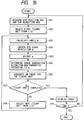
- Fig. 3 is a flow-chart which shows a flow of an image display process in the first embodiment. Details of processing at each of the steps will be explained in order.
- data for a figure unit to be first drawn are selected from the forehead of a figure data list which has been stored in the memory device in a form shown in Fig. 5.
- the items of figure data in the data list are an identification number of figure data, a type of a figure, an image data body and the like.
- an angle ⁇ between a direction 403 from an eye position 402 shown in Fig. 4, to a position 404 where a figure unit is drawn on the screen, and the direction of the eye sight obtained at step 301 is calculated.
- a visual resolution a in a vision position making the angle of ⁇ from the eye sight direction 405 is obtained.
- the value of the visual resolution a is defined so that it becomes highest within a few angle from the center of the retina, as shown in Fig. 6, and exponentially decreases as the angle increases.
- the visual resolution which has a highest value at an angle of zero, that is, at the center of the retina is used as a reference, and the resolution is represented by the normalization with this reference.
- the highest value of the resolution is set to 1, and the visual resolution is defined as a function or a data table relating to the angle ⁇ .
- an image creating algorism and parameters therefor are selected in accordance with the value of the visual resolution.
- an attention is to be paid such that an image of a part corresponding to the center of the retina is precisely created, and the further the distance from the center of the retina, the lower the relative burden of calculation becomes.
- the image creating algorism a scan line process is used if the visual resolution is below a preset threshold value, but a ray tracing process is used if the visual resolution is higher than the threshold value.
- parameters the detail particularity of the figure data varies in accordance with a visual resolution, as shown in Fig. 8.
- the ray tracing process in which the burden of calculation is heavy, but a precise exhibition can be made, is applicable for drawing the center vision part. Meanwhile, the scan line process in which the function of exhibition is restricted, in comparison with the ray tracing process. However, the burden of calculation is light so as to be applicable for drawing the peripheral vision part.
- the detail particularity of figure data which is a parameter varies in accordance with a visual resolution is that for controlling the density of figure data to be drawn.
- a number of figure elements such as polygon patches and line segments which constitute a figure, can be stepwise changed over, at an image creating step which will be explained later.
- an image for a figure unit is created with the use of the algorism and the parameters determined at step 305, and is accumulated in the frame buffer 102.
- the following items as shown in Fig. 9 is controlled with the use of the detail particularity of the figure data as a control parameter.
- the number of polygons to be drawn is a number of polygon patches constituting a figure to be drawn. If the detail particularity is high, the figure is precisely (finely) exhibited by drawing the figure with the use of a larger number of polygon patches.
- a shape 1002 shown in Fig. 10 gives an example in which a sphere is precisely approximated by several polygons. On the contrary, if the detail particularity is low, the drawing is made with a less number of polygon patches so as to reduce the burden of calculation for the drawing.
- a shape 1001 shown in Fig. 10 gives an example in which a sphere is briefly exhibited with a less number of polygons. There are considered two cases, that is, the case of suitably changing over polygon data which have been stepwise prepared, during drawing, and the case of changing the size of division when a surface such an arbitrary curved surface which is defined in a nonpolygon group form, is divided into polygons during the drawing.
- a texture resolution shown in Fig. 9 gives a density of pixels in image data exhibiting a pattern of a figure, and accordingly, the higher the detail particularity, the larger the number of pixels are given so as to precisely exhibit the pattern.
- a texture 1102 shown in Fig. 11 gives an example of texture data having a high resolution of 1024 pixels x 1,024 pixels. On the contrary, if the detail particularity is low, the number of pixels is decreased so as to reduce the burden of calculation for drawing.
- a texture 110 shown in Fig. 11 gives an example of texture data having a low resolution of 16 pixels and 16 pixels.
- step 307 whether images for all figure units to be drawn are created or not is determined, if any of figure units to be drawn remains in the data list, at step 308, a figure unit to be drawn at the next time, is selected from the data list, and the procedure is similarly repeated from step 303. However, if it is determined that the image creating process is completed for all figure units at step 307, an image display process at step 309 is carried out, and accordingly, images accumulated in the frame buffer are exhibited on the image display apparatus.
- step 310 whether the operator instructs that the image display process is ended or not, is determined, and if no instruction is present, the procedure from the step 303 is repeated. Alternatively, if an instruction for ending the process is present, the process is completed.
- FIG. 1 The basic arrangement of this embodiment can be shown by Fig. 1, similar to the first embodiment.
- FIG. 3 A flow-chart for indicating a flow of an image creating and displaying procedure in this embodiment is shown in Fig. 3, similar to the first embodiment, and the details of all process steps in this embodiment are the same as those explained in the first embodiment, except step 305.
- step 305 in this embodiment is essentially similar to that in the first embodiment, however, precisely, it is different therefrom.
- a wire frame expressing process is selected, but if it is higher than the threshold value, a surface expressing process is selected.
- the wire frame expressing process has an inferior function of expression but has a lower burden of calculation since a polygon shape can be drawn by its contour, and accordingly, it is applicable for expression in the peripheral vision part. Meanwhile, the surface expressing process has a burden of calculation, larger than that of the wire frame expressing process, but it can precisely exhibit a polygon shape, and accordingly, it is applicable for expression in the center vision part.
- the above-mentioned threshold can be arbitrarily changed.
- the expression process is altered in view of the threshold value for the visual resolution, and accordingly, the process can be simplified. Further, by arbitrarily changing the threshold value, a figure to be displayed can be set to be fine or rough, that is, the representation can be made, suitable for its use purpose.
- FIG. 2 The positions of detectors in this embodiment is shown in Fig. 2, similar to the first embodiment.
- FIG. 3 A flow-chart for indicating a flow of an image creating and displaying procedure in this embodiment is shown in Fig. 3, similar to the first embodiment, and the details of all process steps in this embodiment are the same as those explained in the first embodiment, except step 305.
- step 305 in this embodiment is essentially similar to that in the first embodiment, however, precisely, it is different therefrom.
- a drawing process is selected in such a way that if the visual resolution is below a preset threshold value, texture mapping is omitted, but if it exceeds the threshold value, the texture mapping is carried out.
- the texture mapping has a large burden of calculation required for creating an image, but can enhance the quality of an image. Accordingly, it is suitable for expression in the center vision part. Further, the texture mapping is omitted in the peripheral vision part, thereby it is possible to greatly reduce the burden of calculation as a whole.
- FIG. 3 A flow-chart for indicating a flow of an image creating and displaying procedure in this embodiment is shown in Fig. 3, similar to the first embodiment, and the details of all process steps in this embodiment are the same as those explained in the first embodiment, except step 305.
- step 305 in this embodiment is essentially similar to that in the first embodiment, however, precisely, it is different therefrom.
- a smooth shading process which is used during drawing, is changed over.
- the smooth shading process is a process which can represent smooth adjacent parts of polygons when a curved surface represented by a polygon approximation is drawn. As shown in Fig. 12, when the visual resolution is below a first threshold value, a flat shading process is selected, and a Gouraud shading process is selected if it is between first and second threshold values, but a Phong shading process is selected if it exceeds the second threshold value.
- the Phong shading process is applicable for drawing a part where the visual resolution is high.
- the flat shading process is a process in which no smooth shading is carried out. With this process, a curved surface obtained by a polygonal approximation is exhibited to be square so as to be visually inferior, but the burden of calculation is small. Accordingly, this process is applicable for drawing a part where the visual resolution is low.
- the Gouraud shading process is positioned between the above-mentioned Phong shading process and the flat shading process in view of the burden of calculation and the quality of a created image, and accordingly, it is applicable for drawing a part where the visual resolution is intermediate.
- FIG. 3 A flow-chart indicating a flow of an image creating and displaying procedure is shown in Fig. 3, similar to the first embodiment, in which the details of all process steps are similar to those explained in the first embodiment, except step 305.
- step 305 in this embodiment is essentially similar to that in the first embodiment, however, precisely, it is different therefrom.
- the maximum number of reflection of a light beam in the case of execution of ray tracing calculation is set to be large if the visual resolution is high, but is set to be small if it is low.
- the quality of the image can be enhanced by setting the number of reflection of a light beam to be large, and accordingly, the ray tracing is applicable for drawing in the center vision part. Meanwhile, the burden of calculation is reduced in the peripheral vision part by reducing the number of reflection.
- FIG. 3 A flow-chart indicating a flow of an image creating and displaying procedure is shown in Fig. 3, similar to the first embodiment, in which the details of all process steps are similar to those explained in the first embodiment, except step 305.
- step 305 in this embodiment is essentially similar to that in the first embodiment, however, precisely, it is different therefrom.
- a mode in which a figure to be drawn is drawn to be semitransparent is selected, and meanwhile, if it is below the threshold value, a mode in which an opaque matter is drawn to be opaque is selected.
- FIG. 3 A flow-chart indicating a flow of an image creating and displaying procedure is shown in Fig. 3, similar to the first embodiment.
- the positions of detectors are different from those in the first embodiment.
- a detector holder 203 is the one adapted to be set on the head of the operator.
- a detector holder has a frame which is glasses frame-like and on which a position and posture detector and an eye movement detector set on the effective eye side are fixed.
- the effective eye side can be determined by the operator who recognizes which one of his eyes is effective, and the eye movement detector is fixed to the effective eye side of the frame.
- the basic arrangement of the present invention is shown in Fig. 14.
- the basic arrangement of this embodiment has an interactive input device 1401 in addition to the basic arrangement of the first embodiment.
- the interactive input device 1401 is a device adapted to reflect a motion of the operator in the content of a process, such as a mouse, a keyboard, a dial box, a three-dimensional sensor or an eye sight input device.
- the positions of devices in this arrangement are shown in Fig. 15.
- the arrangement of the devices in this arrangement has the interactive input device 1401 in addition to the arrangement of the devices in the first embodiment.
- a detector holder may be similar to that in the seventh embodiment.
- Fig. 16 shows a flow-chart indicating a flow of an image creating and displaying procedure in this embodiment.
- step 1601 is added to the flow-chart in the first embodiment.
- the details of the procedure in this embodiment is similar to that explained in the first embodiment, or in any one of the second to sixth embodiments, except additional step 1601.
- the value of the visual resolution determined at the previous step 304 is adjusted in consideration with another factor which greatly affect the visual characteristic of the operator.
- the above-mentioned another factor in consideration is, at first, such a case that the relative angle between the direction of the eye sight and the direction from the eye position to a figure varies.
- the lowering of the eyesight caused in this case is in general known as "moving body eyesight". This situation is caused by the movement of a figure, the rotation of the figure, or a variation in the eye sight direction.
- the adjustment is made such that the value of the visual resolution is multiplied by a coefficient which is larger than 0 but less than 1 so as to aim at reducing the burden of calculation by simplifying the creation of an image.
- a situation to be considered, in addition to the moving body eyesight is such a case that the responsiveness of the interactive operation is sometimes required, rather than the image quality, only during interactive operation at the input device 1401 by the operator.
- the value of the visual resolution is adjusted to be lower at step 1601 during the interactive operation, thereby it is possible to aim at enhancing the responsiveness by simplifying the creation of an image.
- the human eyesight characteristic in which the eyesight is high in the center part of the field of vision, but is low in the peripheral part thereof is used, and accordingly, there can be presented such an advantage that the burden of calculation for an image is reduced as a whole, and a more satisfactory image can be represented to the operator.
Landscapes
- Physics & Mathematics (AREA)
- General Physics & Mathematics (AREA)
- Engineering & Computer Science (AREA)
- Optics & Photonics (AREA)
- Computer Graphics (AREA)
- Theoretical Computer Science (AREA)
- Multimedia (AREA)
- Signal Processing (AREA)
- Controls And Circuits For Display Device (AREA)
- Processing Or Creating Images (AREA)
- Image Generation (AREA)
Applications Claiming Priority (3)
| Application Number | Priority Date | Filing Date | Title |
|---|---|---|---|
| JP11025/94 | 1994-02-02 | ||
| JP1102594 | 1994-02-02 | ||
| JP06011025A JP3143558B2 (ja) | 1994-02-02 | 1994-02-02 | 画像表示方法および装置 |
Publications (3)
| Publication Number | Publication Date |
|---|---|
| EP0666547A2 true EP0666547A2 (de) | 1995-08-09 |
| EP0666547A3 EP0666547A3 (de) | 1996-01-31 |
| EP0666547B1 EP0666547B1 (de) | 2001-06-06 |
Family
ID=11766566
Family Applications (1)
| Application Number | Title | Priority Date | Filing Date |
|---|---|---|---|
| EP95300626A Expired - Lifetime EP0666547B1 (de) | 1994-02-02 | 1995-02-01 | Bildanzeigeverfahren und -gerät |
Country Status (4)
| Country | Link |
|---|---|
| US (1) | US5715384A (de) |
| EP (1) | EP0666547B1 (de) |
| JP (1) | JP3143558B2 (de) |
| DE (1) | DE69521155T2 (de) |
Cited By (3)
| Publication number | Priority date | Publication date | Assignee | Title |
|---|---|---|---|---|
| EP0837603A3 (de) * | 1996-07-26 | 1998-09-02 | SORENSEN, Jens Ole | System zum Steuern der Fokusierung von Linsen mit einer variablen Fokusierung mittels einer Detektion der räumlichen Beziehung der Augen einer Person |
| EP1510849A1 (de) | 2003-08-29 | 2005-03-02 | C.R.F. Società Consortile per Azioni | Virtuelles Anzeigegerät für ein Fahrzeug |
| EP1355276A3 (de) * | 2002-04-16 | 2005-05-11 | Sony Computer Entertainment Inc. | Verfahren und Vorrichtung zur entfernungsangepassten Bilddarstellung |
Families Citing this family (17)
| Publication number | Priority date | Publication date | Assignee | Title |
|---|---|---|---|---|
| US6268862B1 (en) | 1996-03-08 | 2001-07-31 | Canon Kabushiki Kaisha | Three dimensional virtual space generation by fusing images |
| JP4607259B2 (ja) * | 1996-05-22 | 2011-01-05 | クゥアルコム・インコーポレイテッド | 感知された状況に応じて電気デバイスを制御する方法及び装置 |
| US6804726B1 (en) | 1996-05-22 | 2004-10-12 | Geovector Corporation | Method and apparatus for controlling electrical devices in response to sensed conditions |
| US5859642A (en) * | 1996-09-26 | 1999-01-12 | Sandia Corporation | Virtual button interface |
| US6191793B1 (en) | 1998-04-01 | 2001-02-20 | Real 3D, Inc. | Method and apparatus for texture level of detail dithering |
| US6421051B1 (en) * | 1998-06-18 | 2002-07-16 | Spatial Corporation | Multi-resolution geometry |
| US6532311B1 (en) | 1999-02-26 | 2003-03-11 | Lockheed Martin Corporation | Image browser |
| JP4632531B2 (ja) * | 2000-12-18 | 2011-02-16 | 株式会社バンダイナムコゲームス | ゲームシステム、情報記憶媒体及びゲームシステムの制御方法 |
| US6953249B1 (en) | 2001-01-29 | 2005-10-11 | Maguire Jr Francis J | Method and devices for displaying images for viewing with varying accommodation |
| JP2003016375A (ja) * | 2001-06-29 | 2003-01-17 | Matsushita Electric Works Ltd | 対話型シミュレーションシステム、そのプログラム、シミュレーション支援方法 |
| US7173619B2 (en) * | 2004-07-08 | 2007-02-06 | Microsoft Corporation | Matching digital information flow to a human perception system |
| EP1720357A1 (de) * | 2005-05-04 | 2006-11-08 | Swisscom Mobile AG | Verfahren und Vorrichtung zur Übermittlung von Videodaten mit Komprimierung basierend auf Blickrichtung nach Augenverfolgungsverfahren |
| KR100818286B1 (ko) | 2006-11-23 | 2008-04-01 | 삼성전자주식회사 | 안개 효과를 고려하여 3차원 그래픽스 데이터를 렌더링하는방법 및 장치 |
| JP5003252B2 (ja) * | 2007-04-04 | 2012-08-15 | 凸版印刷株式会社 | 画像表示装置及び画像表示方法 |
| KR101824501B1 (ko) * | 2011-05-19 | 2018-02-01 | 삼성전자 주식회사 | 헤드 마운트 디스플레이 장치의 이미지 표시 제어 장치 및 방법 |
| TW201634974A (zh) * | 2015-03-26 | 2016-10-01 | Chipone Technology Beijing Co Ltd | 頭戴式顯示系統及影像低頻寬傳輸方法 |
| CN111684336A (zh) | 2018-02-09 | 2020-09-18 | 国立大学法人福井大学 | 使用了视网膜扫描型显示部的图像显示装置及其方法 |
Family Cites Families (10)
| Publication number | Priority date | Publication date | Assignee | Title |
|---|---|---|---|---|
| EP0513474A1 (de) * | 1986-09-11 | 1992-11-19 | Hughes Aircraft Company | Digitales System für visuelle und Sensorsimulation zur Erzeugung von realistischen Szenen |
| GB8701288D0 (en) * | 1987-01-21 | 1987-02-25 | Waldern J D | Perception of computer-generated imagery |
| US5293187A (en) * | 1992-02-05 | 1994-03-08 | Biocontrol Systems, Inc. | Method and apparatus for eye tracking for convergence and strabismus measurement |
| US5360971A (en) * | 1992-03-31 | 1994-11-01 | The Research Foundation State University Of New York | Apparatus and method for eye tracking interface |
| JP3318680B2 (ja) * | 1992-04-28 | 2002-08-26 | サン・マイクロシステムズ・インコーポレーテッド | 画像生成方法及び画像生成装置 |
| US5394483A (en) * | 1992-06-30 | 1995-02-28 | Eastman Kodak Co | Method and apparatus for determining visually perceptible differences between images |
| US5467104A (en) * | 1992-10-22 | 1995-11-14 | Board Of Regents Of The University Of Washington | Virtual retinal display |
| US5345281A (en) * | 1992-12-17 | 1994-09-06 | John Taboada | Eye tracking system and method |
| US5422653A (en) * | 1993-01-07 | 1995-06-06 | Maguire, Jr.; Francis J. | Passive virtual reality |
| US5400177A (en) * | 1993-11-23 | 1995-03-21 | Petitto; Tony | Technique for depth of field viewing of images with improved clarity and contrast |
-
1994
- 1994-02-02 JP JP06011025A patent/JP3143558B2/ja not_active Expired - Fee Related
-
1995
- 1995-02-01 DE DE69521155T patent/DE69521155T2/de not_active Expired - Lifetime
- 1995-02-01 US US08/384,530 patent/US5715384A/en not_active Expired - Lifetime
- 1995-02-01 EP EP95300626A patent/EP0666547B1/de not_active Expired - Lifetime
Cited By (3)
| Publication number | Priority date | Publication date | Assignee | Title |
|---|---|---|---|---|
| EP0837603A3 (de) * | 1996-07-26 | 1998-09-02 | SORENSEN, Jens Ole | System zum Steuern der Fokusierung von Linsen mit einer variablen Fokusierung mittels einer Detektion der räumlichen Beziehung der Augen einer Person |
| EP1355276A3 (de) * | 2002-04-16 | 2005-05-11 | Sony Computer Entertainment Inc. | Verfahren und Vorrichtung zur entfernungsangepassten Bilddarstellung |
| EP1510849A1 (de) | 2003-08-29 | 2005-03-02 | C.R.F. Società Consortile per Azioni | Virtuelles Anzeigegerät für ein Fahrzeug |
Also Published As
| Publication number | Publication date |
|---|---|
| US5715384A (en) | 1998-02-03 |
| EP0666547A3 (de) | 1996-01-31 |
| DE69521155T2 (de) | 2001-10-31 |
| JP3143558B2 (ja) | 2001-03-07 |
| JPH07220114A (ja) | 1995-08-18 |
| DE69521155D1 (de) | 2001-07-12 |
| EP0666547B1 (de) | 2001-06-06 |
Similar Documents
| Publication | Publication Date | Title |
|---|---|---|
| EP0666547A2 (de) | Bildanzeigeverfahren und -gerät | |
| US11314325B2 (en) | Eye tracking to adjust region-of-interest (ROI) for compressing images for transmission | |
| US6618054B2 (en) | Dynamic depth-of-field emulation based on eye-tracking | |
| US10169846B2 (en) | Selective peripheral vision filtering in a foveated rendering system | |
| US5379371A (en) | Displaying method and apparatus for three-dimensional computer graphics | |
| US8325185B2 (en) | Computer-readable recording medium which stores rendering program, rendering apparatus and rendering method | |
| JPH08111877A (ja) | 立体画像表示方法および装置 | |
| JP5560858B2 (ja) | 補正値算出装置、補正値算出方法および補正値算出プログラム | |
| EP1146328B1 (de) | Darstellung der Leistung eines Brillenglases durch eine Indexanzeige in visuell verständlicher Weise | |
| JP3124999B1 (ja) | レンダリング方法及び装置、ゲーム装置、並びに仮想空間内のオブジェクトの陰影に関するデータを計算するためのプログラムを格納するコンピュータ読み取り可能な記録媒体 | |
| US6979084B2 (en) | Method for evaluating binocular performance of spectacle lenses, method for displaying binocular performance, and apparatus therefore | |
| CN115761089A (zh) | 图像渲染方法、装置、头戴显示设备和可读存储介质 | |
| JP4125251B2 (ja) | 情報処理方法および装置 | |
| Luebke et al. | Perceptually driven simplification using gaze-directed rendering | |
| CN115686219A (zh) | 图像渲染方法、头戴显示设备和可读存储介质 | |
| CN115713783A (zh) | 图像渲染方法、装置、头戴显示设备和可读存储介质 | |
| JP6849826B2 (ja) | 画像処理装置および表示画像生成方法 | |
| JPH08215149A (ja) | 眼光学系のシミュレーション装置 | |
| JP2677233B2 (ja) | コンピュータグラフィックス表示方法 | |
| JP3919069B2 (ja) | 眼鏡レンズ性能表示方法及び装置 | |
| JP6965374B2 (ja) | 画像処理装置および表示画像生成方法 | |
| JP3586253B2 (ja) | テクスチャマッピングプログラム | |
| EP1330785B1 (de) | Auf augennachführung basierte dynamische tiefenschärfeemulation | |
| KR20230063463A (ko) | 선택적 샘플링에 기반을 둔 가상 현실 헤드셋용 광선 추적 방법 | |
| JPH0831126B2 (ja) | 眼鏡装用シミュレーション装置における合成画像作成方法 |
Legal Events
| Date | Code | Title | Description |
|---|---|---|---|
| PUAI | Public reference made under article 153(3) epc to a published international application that has entered the european phase |
Free format text: ORIGINAL CODE: 0009012 |
|
| AK | Designated contracting states |
Kind code of ref document: A2 Designated state(s): DE FR GB IT NL |
|
| PUAL | Search report despatched |
Free format text: ORIGINAL CODE: 0009013 |
|
| AK | Designated contracting states |
Kind code of ref document: A3 Designated state(s): DE FR GB IT NL |
|
| 17P | Request for examination filed |
Effective date: 19960612 |
|
| 17Q | First examination report despatched |
Effective date: 19990504 |
|
| GRAG | Despatch of communication of intention to grant |
Free format text: ORIGINAL CODE: EPIDOS AGRA |
|
| GRAG | Despatch of communication of intention to grant |
Free format text: ORIGINAL CODE: EPIDOS AGRA |
|
| GRAH | Despatch of communication of intention to grant a patent |
Free format text: ORIGINAL CODE: EPIDOS IGRA |
|
| GRAH | Despatch of communication of intention to grant a patent |
Free format text: ORIGINAL CODE: EPIDOS IGRA |
|
| GRAA | (expected) grant |
Free format text: ORIGINAL CODE: 0009210 |
|
| AK | Designated contracting states |
Kind code of ref document: B1 Designated state(s): DE FR GB IT NL |
|
| PG25 | Lapsed in a contracting state [announced via postgrant information from national office to epo] |
Ref country code: NL Free format text: LAPSE BECAUSE OF FAILURE TO SUBMIT A TRANSLATION OF THE DESCRIPTION OR TO PAY THE FEE WITHIN THE PRESCRIBED TIME-LIMIT Effective date: 20010606 Ref country code: IT Free format text: LAPSE BECAUSE OF FAILURE TO SUBMIT A TRANSLATION OF THE DESCRIPTION OR TO PAY THE FEE WITHIN THE PRE;WARNING: LAPSES OF ITALIAN PATENTS WITH EFFECTIVE DATE BEFORE 2007 MAY HAVE OCCURRED AT ANY TIME BEFORE 2007. THE CORRECT EFFECTIVE DATE MAY BE DIFFERENT FROM THE ONE RECORDED.SCRIBED TIME-LIMIT Effective date: 20010606 Ref country code: FR Free format text: LAPSE BECAUSE OF FAILURE TO SUBMIT A TRANSLATION OF THE DESCRIPTION OR TO PAY THE FEE WITHIN THE PRESCRIBED TIME-LIMIT Effective date: 20010606 |
|
| REF | Corresponds to: |
Ref document number: 69521155 Country of ref document: DE Date of ref document: 20010712 |
|
| NLV1 | Nl: lapsed or annulled due to failure to fulfill the requirements of art. 29p and 29m of the patents act | ||
| EN | Fr: translation not filed | ||
| REG | Reference to a national code |
Ref country code: GB Ref legal event code: IF02 |
|
| PLBE | No opposition filed within time limit |
Free format text: ORIGINAL CODE: 0009261 |
|
| STAA | Information on the status of an ep patent application or granted ep patent |
Free format text: STATUS: NO OPPOSITION FILED WITHIN TIME LIMIT |
|
| 26N | No opposition filed | ||
| PGFP | Annual fee paid to national office [announced via postgrant information from national office to epo] |
Ref country code: GB Payment date: 20130220 Year of fee payment: 19 Ref country code: DE Payment date: 20130228 Year of fee payment: 19 |
|
| REG | Reference to a national code |
Ref country code: DE Ref legal event code: R119 Ref document number: 69521155 Country of ref document: DE |
|
| GBPC | Gb: european patent ceased through non-payment of renewal fee |
Effective date: 20140201 |
|
| REG | Reference to a national code |
Ref country code: DE Ref legal event code: R119 Ref document number: 69521155 Country of ref document: DE Effective date: 20140902 |
|
| PG25 | Lapsed in a contracting state [announced via postgrant information from national office to epo] |
Ref country code: DE Free format text: LAPSE BECAUSE OF NON-PAYMENT OF DUE FEES Effective date: 20140902 Ref country code: GB Free format text: LAPSE BECAUSE OF NON-PAYMENT OF DUE FEES Effective date: 20140201 |