EP0666576A2 - Câble d'énergie - Google Patents
Câble d'énergie Download PDFInfo
- Publication number
- EP0666576A2 EP0666576A2 EP95100754A EP95100754A EP0666576A2 EP 0666576 A2 EP0666576 A2 EP 0666576A2 EP 95100754 A EP95100754 A EP 95100754A EP 95100754 A EP95100754 A EP 95100754A EP 0666576 A2 EP0666576 A2 EP 0666576A2
- Authority
- EP
- European Patent Office
- Prior art keywords
- protective tube
- shield wires
- power cable
- shield
- wires
- Prior art date
- Legal status (The legal status is an assumption and is not a legal conclusion. Google has not performed a legal analysis and makes no representation as to the accuracy of the status listed.)
- Granted
Links
- 230000001681 protective effect Effects 0.000 claims abstract description 48
- 239000004020 conductor Substances 0.000 claims abstract description 4
- 238000010292 electrical insulation Methods 0.000 claims abstract description 4
- 239000002356 single layer Substances 0.000 claims abstract description 4
- 239000013307 optical fiber Substances 0.000 claims description 10
- RYGMFSIKBFXOCR-UHFFFAOYSA-N Copper Chemical compound [Cu] RYGMFSIKBFXOCR-UHFFFAOYSA-N 0.000 claims description 6
- 229910052802 copper Inorganic materials 0.000 claims description 6
- 239000010949 copper Substances 0.000 claims description 6
- 229910001220 stainless steel Inorganic materials 0.000 claims description 3
- 239000010935 stainless steel Substances 0.000 claims description 3
- 230000003287 optical effect Effects 0.000 abstract description 8
- 239000010410 layer Substances 0.000 description 7
- 238000004519 manufacturing process Methods 0.000 description 4
- 230000005540 biological transmission Effects 0.000 description 3
- 230000004888 barrier function Effects 0.000 description 1
- 238000009529 body temperature measurement Methods 0.000 description 1
- 239000006229 carbon black Substances 0.000 description 1
- 230000007423 decrease Effects 0.000 description 1
- 238000011161 development Methods 0.000 description 1
- 230000018109 developmental process Effects 0.000 description 1
- 238000009792 diffusion process Methods 0.000 description 1
- 230000001771 impaired effect Effects 0.000 description 1
- 238000009434 installation Methods 0.000 description 1
- 239000002184 metal Substances 0.000 description 1
- 229910052751 metal Inorganic materials 0.000 description 1
- 238000012544 monitoring process Methods 0.000 description 1
- 230000007704 transition Effects 0.000 description 1
- 238000009827 uniform distribution Methods 0.000 description 1
Images

Classifications
-
- G—PHYSICS
- G02—OPTICS
- G02B—OPTICAL ELEMENTS, SYSTEMS OR APPARATUS
- G02B6/00—Light guides; Structural details of arrangements comprising light guides and other optical elements, e.g. couplings
- G02B6/44—Mechanical structures for providing tensile strength and external protection for fibres, e.g. optical transmission cables
- G02B6/4401—Optical cables
- G02B6/4415—Cables for special applications
-
- H—ELECTRICITY
- H01—ELECTRIC ELEMENTS
- H01B—CABLES; CONDUCTORS; INSULATORS; SELECTION OF MATERIALS FOR THEIR CONDUCTIVE, INSULATING OR DIELECTRIC PROPERTIES
- H01B9/00—Power cables
- H01B9/005—Power cables including optical transmission elements
Definitions
- the invention relates to a power cable according to the preamble of claim 1 (EP 0 203 249 B1).
- optical fibers are arranged for their mechanical protection in protective tubes made of plastic or metal between the shield wires of an energy cable, these protective tubes generally have a larger outer diameter than the shield wires usually used in the shield of an energy cable.
- these protective tubes there is a risk, in particular in the manufacture of the cable, but also in the laying thereof, that the in In the radial direction outwardly protruding protective tubes protrude from the outside in radial direction on the cable and thus in particular on the protective tubes protruding beyond the shield wires, the transmission properties of the optical fibers and, if the optical fibers are used as sensors, their sensor properties are at least impaired .
- the invention is based on the problem of protecting the protective tubes of the optical waveguides arranged between the shield wires during manufacture and laying of the energy cable, in particular against compressive forces acting in the radial direction of the cable, and thus ensuring reliable functioning of the optical fibers.
- the invention is based on the knowledge that the support elements provided between the at least one protective tube and the shield wires, which protrude outward beyond the shield wires in the radial direction of the power cable, lead to a more uniform distribution of the compressive forces acting on the power cable from the outside, and so that Protect a larger outer diameter than the protective tubes having the shielding wires and the optical waveguide running therein against impermissibly high compressive forces acting in the radial direction or in the circumferential direction of the cable. The occurrence of punctual pressure points on the protective tubes that protrude outward from the shield wires is effectively avoided. Much of the shield can still be made from any thinner shielding wire according to the provided screen cross-section are formed. The elongated support elements can be easily roped together with the shield wires and the at least one protective tube onto the cable core.
- the protective tube is particularly effectively protected from external pressure forces acting on the cable and thus an impermissibly high mechanical load on the protective tube and the optical waveguide running therein. B. avoided at specific pressure points.
- At least two support elements are arranged between the at least one protective tube and the adjacent shield wires.
- the support elements have a circular cross section and, like the shield wires, are made of copper.
- the protective tube is designed in the form of a stainless steel tube.
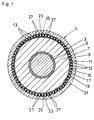
- FIG. 1 shows a first exemplary embodiment according to the invention
- FIG. 2 shows a second exemplary embodiment according to the invention of the power cable.
- the power cables 1 shown by way of example in FIGS. 1 and 2 have an electrical conductor 3 which is surrounded by an inner conductive layer 5. Electrical insulation 7 is provided above this inner conductive layer 5 and is in turn enclosed by an outer conductive layer 9. At the outer conductive layer 9 z. B. a cushion layer 11 formed from a carbon black paper. Shield wires 13, for example made of copper and having a circular cross section, are roped onto the cushion layer 11 next to one another, which together form a single-layer shield 15. A second cushion layer 17 and an overlying diffusion barrier 19 are provided above the screen 15. In the radial outward direction, the energy cable 1 is closed by an outer jacket 21.
- a protective tube 23, for example, is arranged in each case at two opposite points of the screen 15 in the circumferential direction of the cable 1 between the screen wires 13.
- B. is made of stainless steel, but can also consist of a plastic.
- the outer diameter of the protective tube 23 with z. B. about 1.2 to 1.5 mm larger than the diameter of the Shield wires 13.
- At least one, for example exactly one, optical waveguide 25 runs in the two protective tubes 23. B. for continuous temperature measurement over the entire length of the power cable 1; but they can also be used, for example, as pressure sensors or for information transmission.
- At least one elongated support element 27 is arranged on each side of the opposite protective tube 23 between the respective protective tube 23 and the adjacent shield wires 13, which protrudes outward beyond the shield wires 13 in the radial direction of the power cable 1.
- two such support elements 27 are provided, which are designed for example in the form of copper wires with a circular cross section.
- plastic strips or any other elements with a round, square or rectangular cross section can also be used as support elements.
- the extension of the support elements 27 in the radial direction of the energy cable 1 to the outside is at least as large as the extension of the protective tubes 23 in this direction.
- the support elements 27 in the form of copper wires have the same outer diameter as the protective tubes 23, so that the protective tubes 23 do not have the neighboring ones Protruding elements of the screen 15.
- the support elements 27 do not all have the same dimensions or the same diameter, but that their extension in the radial direction of the cable 1, as seen outwardly in the circumferential direction, decreases towards the shield wires 13 or that their extension in this direction to the protective tube 23 increases, so that there is a smooth transition between the shield wires 13 with a smaller diameter and the protective tube 23 with a larger diameter and the latter are particularly effectively protected against inadmissible mechanical stresses from external pressure forces.
- the majority of the screen 15 can furthermore be provided with any desired, thinner screen wires 13 in accordance with the intended screen cross-section while observing any gap requirements.
- the second exemplary embodiment of the invention shown in FIG. 2 differs from the first exemplary embodiment shown in FIG. 1 essentially only in that at one point on the screen 15 of the power cable 1 two adjacent protective tubes 23 with z. B. each an optical fiber 25 are arranged. Between the sides of the protective tube 23 facing away from the other protective tube 23 and the adjacent shield wires 13 there are two supporting elements 27, for. B. arranged in the form of a circular cross-section copper wires.
- the support elements 27 in the radial direction of the power cable 1 to the outside for example, have a greater extension than the protective tubes 23 in this direction, so that the support elements 27 protrude beyond the protective tubes 23 in the radial direction to the outside.
- the protective tubes 23 with the inserted optical waveguides 25 are protected in a simple and very effective manner from damage by pressure forces acting in the radial direction from the outside.
Landscapes
- Physics & Mathematics (AREA)
- General Physics & Mathematics (AREA)
- Optics & Photonics (AREA)
- Communication Cables (AREA)
- Insulated Conductors (AREA)
- Laying Of Electric Cables Or Lines Outside (AREA)
- Details Of Connecting Devices For Male And Female Coupling (AREA)
- Cable Accessories (AREA)
- Electrical Discharge Machining, Electrochemical Machining, And Combined Machining (AREA)
- Organic Insulating Materials (AREA)
Applications Claiming Priority (2)
| Application Number | Priority Date | Filing Date | Title |
|---|---|---|---|
| DE4403266 | 1994-02-03 | ||
| DE4403266A DE4403266C1 (de) | 1994-02-03 | 1994-02-03 | Energiekabel |
Publications (3)
| Publication Number | Publication Date |
|---|---|
| EP0666576A2 true EP0666576A2 (fr) | 1995-08-09 |
| EP0666576A3 EP0666576A3 (fr) | 1996-10-30 |
| EP0666576B1 EP0666576B1 (fr) | 1999-10-13 |
Family
ID=6509353
Family Applications (1)
| Application Number | Title | Priority Date | Filing Date |
|---|---|---|---|
| EP95100754A Expired - Lifetime EP0666576B1 (fr) | 1994-02-03 | 1995-01-20 | Câble d'énergie |
Country Status (4)
| Country | Link |
|---|---|
| EP (1) | EP0666576B1 (fr) |
| AT (1) | ATE185647T1 (fr) |
| DE (2) | DE4403266C1 (fr) |
| DK (1) | DK0666576T3 (fr) |
Cited By (2)
| Publication number | Priority date | Publication date | Assignee | Title |
|---|---|---|---|---|
| GB2302184B (en) * | 1995-06-09 | 1999-09-08 | Gen Electric Co Plc | Composite cable for electrical power and communication signals |
| EP4489034A1 (fr) * | 2023-07-05 | 2025-01-08 | Nexans | Procédé de fabrication d'un câble électrique composite |
Families Citing this family (1)
| Publication number | Priority date | Publication date | Assignee | Title |
|---|---|---|---|---|
| FR2769748B1 (fr) * | 1997-10-10 | 1999-12-24 | Telecommunications Sa | Cable composite a conducteur de puissance et fibres optiques |
Family Cites Families (7)
| Publication number | Priority date | Publication date | Assignee | Title |
|---|---|---|---|---|
| GB1422147A (en) * | 1972-06-06 | 1976-01-21 | Bicc Ltd | Optical guides |
| DE7714167U1 (de) * | 1977-05-05 | 1977-08-25 | Kabelwerke Friedrich C. Ehlers, 2000 Hamburg | Elektrisches Kabel |
| FR2529373A1 (fr) * | 1982-06-29 | 1983-12-30 | Thomson Jeumont Cables | Cable isole pour le transport d'energie electrique notamment a haute tension |
| DE8515470U1 (de) * | 1985-05-25 | 1985-12-19 | Felten & Guilleaume Energietechnik Gmbh, 5000 Koeln | Starkstromkabel, insbesondere für Spannungen von 6 bis 60 kV, mit eingelegten Lichtwellenleitern |
| JPS6364218A (ja) * | 1986-09-05 | 1988-03-22 | 株式会社フジクラ | 複合電力ケ−ブル |
| DE3820730A1 (de) * | 1988-06-18 | 1989-12-21 | Philips Patentverwaltung | Freileiter mit einer optischen nachrichtenleitung |
| DE4333827C2 (de) * | 1993-09-30 | 2003-08-07 | Pirelli Cavi E Sistemi Spa | Energieübertragungskabel mit Lichtwellenleiterelement |
-
1994
- 1994-02-03 DE DE4403266A patent/DE4403266C1/de not_active Expired - Fee Related
-
1995
- 1995-01-20 AT AT95100754T patent/ATE185647T1/de not_active IP Right Cessation
- 1995-01-20 DK DK95100754T patent/DK0666576T3/da active
- 1995-01-20 EP EP95100754A patent/EP0666576B1/fr not_active Expired - Lifetime
- 1995-01-20 DE DE59507011T patent/DE59507011D1/de not_active Expired - Lifetime
Cited By (2)
| Publication number | Priority date | Publication date | Assignee | Title |
|---|---|---|---|---|
| GB2302184B (en) * | 1995-06-09 | 1999-09-08 | Gen Electric Co Plc | Composite cable for electrical power and communication signals |
| EP4489034A1 (fr) * | 2023-07-05 | 2025-01-08 | Nexans | Procédé de fabrication d'un câble électrique composite |
Also Published As
| Publication number | Publication date |
|---|---|
| EP0666576B1 (fr) | 1999-10-13 |
| EP0666576A3 (fr) | 1996-10-30 |
| DK0666576T3 (da) | 1999-12-27 |
| DE59507011D1 (de) | 1999-11-18 |
| DE4403266C1 (de) | 1995-04-06 |
| ATE185647T1 (de) | 1999-10-15 |
Similar Documents
| Publication | Publication Date | Title |
|---|---|---|
| DE3041679C2 (fr) | ||
| DE69021674T2 (de) | Optische Faser beinhaltendes Unterwasserkabel. | |
| DE3883045T2 (de) | Elektrisches Energiekabel mit Übertragung optischer Signale. | |
| DE2851955C2 (fr) | ||
| DE3015732C2 (de) | Freileitungsseil mit in seinem Inneren angeordneten Lichtleitfasern | |
| DE3586290T2 (de) | Optisches kabel. | |
| DE2523738A1 (de) | Nachrichtenkabel | |
| DE2820510A1 (de) | Flexibler verseilter koerper, insbesondere elektrischer freileiter | |
| DE3023398A1 (de) | Seekabel mit optischen fasern | |
| DE2854746A1 (de) | Optisches kabel | |
| DE19641616B4 (de) | Nachrichtenkabel mit im Bereich des Außenmantels angebrachten Zugentlastungselementen | |
| DE3689697T2 (de) | Heterogenes Freiluftstarkstromkabel. | |
| DE29618796U1 (de) | Flexible Leitung | |
| DE2801231C2 (de) | Mit Isoliermaterial ummanteltes Starkstromkabel | |
| DE69016443T2 (de) | Abgestufter kabelblock. | |
| EP0042996A2 (fr) | Câble d'information optique autoportant | |
| DE3012638A1 (de) | Glasfaserkabel mit mitteln zur ermoeglichung einer ortung | |
| DE3538664C2 (fr) | ||
| DE4403266C1 (de) | Energiekabel | |
| EP0311751B1 (fr) | Ligne courant fort flexible, en particulier câble pour sevices durs avec des conducteurs d'ondes de lumière intégrés. | |
| DE29520915U1 (de) | Nachrichtenkabel | |
| EP0996014B1 (fr) | Câble aérien isolé comportant un guide d'onde optique | |
| WO2006061370A1 (fr) | Guide d'ondes optiques en bande a plusieurs monofibres optiques et procede de fabrication dudit guide | |
| DE19508888C2 (de) | Flexible elektrische Starkstromleitung | |
| DE29518024U1 (de) | Nachrichtenkabel |
Legal Events
| Date | Code | Title | Description |
|---|---|---|---|
| PUAI | Public reference made under article 153(3) epc to a published international application that has entered the european phase |
Free format text: ORIGINAL CODE: 0009012 |
|
| AK | Designated contracting states |
Kind code of ref document: A2 Designated state(s): AT BE CH DE DK FR GB LI NL SE |
|
| RBV | Designated contracting states (corrected) |
Designated state(s): AT BE CH DE DK FR GB LI NL SE |
|
| PUAL | Search report despatched |
Free format text: ORIGINAL CODE: 0009013 |
|
| AK | Designated contracting states |
Kind code of ref document: A3 Designated state(s): AT BE CH DE DK FR GB LI NL SE |
|
| 17P | Request for examination filed |
Effective date: 19960914 |
|
| 17Q | First examination report despatched |
Effective date: 19971014 |
|
| GRAG | Despatch of communication of intention to grant |
Free format text: ORIGINAL CODE: EPIDOS AGRA |
|
| GRAG | Despatch of communication of intention to grant |
Free format text: ORIGINAL CODE: EPIDOS AGRA |
|
| GRAH | Despatch of communication of intention to grant a patent |
Free format text: ORIGINAL CODE: EPIDOS IGRA |
|
| RAP1 | Party data changed (applicant data changed or rights of an application transferred) |
Owner name: ALCATEL |
|
| GRAH | Despatch of communication of intention to grant a patent |
Free format text: ORIGINAL CODE: EPIDOS IGRA |
|
| GRAA | (expected) grant |
Free format text: ORIGINAL CODE: 0009210 |
|
| AK | Designated contracting states |
Kind code of ref document: B1 Designated state(s): AT BE CH DE DK FR GB LI NL SE |
|
| REF | Corresponds to: |
Ref document number: 185647 Country of ref document: AT Date of ref document: 19991015 Kind code of ref document: T |
|
| REG | Reference to a national code |
Ref country code: CH Ref legal event code: EP |
|
| REF | Corresponds to: |
Ref document number: 59507011 Country of ref document: DE Date of ref document: 19991118 |
|
| REG | Reference to a national code |
Ref country code: CH Ref legal event code: NV Representative=s name: CABINET ROLAND NITHARDT CONSEILS EN PROPRIETE INDU |
|
| REG | Reference to a national code |
Ref country code: DK Ref legal event code: T3 |
|
| PG25 | Lapsed in a contracting state [announced via postgrant information from national office to epo] |
Ref country code: AT Free format text: LAPSE BECAUSE OF NON-PAYMENT OF DUE FEES Effective date: 20000120 |
|
| PG25 | Lapsed in a contracting state [announced via postgrant information from national office to epo] |
Ref country code: BE Free format text: LAPSE BECAUSE OF NON-PAYMENT OF DUE FEES Effective date: 20000131 |
|
| ET | Fr: translation filed | ||
| BERE | Be: lapsed |
Owner name: ALCATEL Effective date: 20000131 |
|
| PLBE | No opposition filed within time limit |
Free format text: ORIGINAL CODE: 0009261 |
|
| STAA | Information on the status of an ep patent application or granted ep patent |
Free format text: STATUS: NO OPPOSITION FILED WITHIN TIME LIMIT |
|
| 26N | No opposition filed | ||
| REG | Reference to a national code |
Ref country code: CH Ref legal event code: PUE Owner name: ALCATEL TRANSFER- NEXANS |
|
| NLS | Nl: assignments of ep-patents |
Owner name: NEXANS |
|
| REG | Reference to a national code |
Ref country code: GB Ref legal event code: 732E |
|
| REG | Reference to a national code |
Ref country code: GB Ref legal event code: IF02 |
|
| PGFP | Annual fee paid to national office [announced via postgrant information from national office to epo] |
Ref country code: DK Payment date: 20030117 Year of fee payment: 9 |
|
| PGFP | Annual fee paid to national office [announced via postgrant information from national office to epo] |
Ref country code: NL Payment date: 20030130 Year of fee payment: 9 |
|
| PG25 | Lapsed in a contracting state [announced via postgrant information from national office to epo] |
Ref country code: DK Free format text: LAPSE BECAUSE OF NON-PAYMENT OF DUE FEES Effective date: 20040202 |
|
| PG25 | Lapsed in a contracting state [announced via postgrant information from national office to epo] |
Ref country code: NL Free format text: LAPSE BECAUSE OF NON-PAYMENT OF DUE FEES Effective date: 20040801 |
|
| REG | Reference to a national code |
Ref country code: DK Ref legal event code: EBP |
|
| NLV4 | Nl: lapsed or anulled due to non-payment of the annual fee |
Effective date: 20040801 |
|
| PGFP | Annual fee paid to national office [announced via postgrant information from national office to epo] |
Ref country code: DE Payment date: 20140122 Year of fee payment: 20 Ref country code: CH Payment date: 20140121 Year of fee payment: 20 Ref country code: SE Payment date: 20140121 Year of fee payment: 20 |
|
| PGFP | Annual fee paid to national office [announced via postgrant information from national office to epo] |
Ref country code: FR Payment date: 20140123 Year of fee payment: 20 |
|
| PGFP | Annual fee paid to national office [announced via postgrant information from national office to epo] |
Ref country code: GB Payment date: 20140121 Year of fee payment: 20 |
|
| REG | Reference to a national code |
Ref country code: DE Ref legal event code: R071 Ref document number: 59507011 Country of ref document: DE |
|
| REG | Reference to a national code |
Ref country code: CH Ref legal event code: PL |
|
| REG | Reference to a national code |
Ref country code: GB Ref legal event code: PE20 Expiry date: 20150119 |
|
| REG | Reference to a national code |
Ref country code: SE Ref legal event code: EUG |
|
| PG25 | Lapsed in a contracting state [announced via postgrant information from national office to epo] |
Ref country code: GB Free format text: LAPSE BECAUSE OF EXPIRATION OF PROTECTION Effective date: 20150119 |