EP0666703A1 - Circuit de commande pour transistor de puissance pour appareil de chauffage par induction - Google Patents
Circuit de commande pour transistor de puissance pour appareil de chauffage par induction Download PDFInfo
- Publication number
- EP0666703A1 EP0666703A1 EP94300927A EP94300927A EP0666703A1 EP 0666703 A1 EP0666703 A1 EP 0666703A1 EP 94300927 A EP94300927 A EP 94300927A EP 94300927 A EP94300927 A EP 94300927A EP 0666703 A1 EP0666703 A1 EP 0666703A1
- Authority
- EP
- European Patent Office
- Prior art keywords
- power transistor
- circuit
- driving circuit
- transistors
- power
- Prior art date
- Legal status (The legal status is an assumption and is not a legal conclusion. Google has not performed a legal analysis and makes no representation as to the accuracy of the status listed.)
- Withdrawn
Links
- 238000010438 heat treatment Methods 0.000 title claims abstract description 14
- 230000005674 electromagnetic induction Effects 0.000 title claims abstract description 11
- 230000006698 induction Effects 0.000 claims abstract description 16
- 230000009977 dual effect Effects 0.000 claims description 2
- 230000001052 transient effect Effects 0.000 description 5
- 230000015556 catabolic process Effects 0.000 description 3
- 238000004904 shortening Methods 0.000 description 2
- 238000010276 construction Methods 0.000 description 1
- 238000010586 diagram Methods 0.000 description 1
- 230000000694 effects Effects 0.000 description 1
- 238000001914 filtration Methods 0.000 description 1
- 230000033001 locomotion Effects 0.000 description 1
- 238000000034 method Methods 0.000 description 1
- 230000002035 prolonged effect Effects 0.000 description 1
- 230000001105 regulatory effect Effects 0.000 description 1
Images

Classifications
-
- H—ELECTRICITY
- H05—ELECTRIC TECHNIQUES NOT OTHERWISE PROVIDED FOR
- H05B—ELECTRIC HEATING; ELECTRIC LIGHT SOURCES NOT OTHERWISE PROVIDED FOR; CIRCUIT ARRANGEMENTS FOR ELECTRIC LIGHT SOURCES, IN GENERAL
- H05B6/00—Heating by electric, magnetic or electromagnetic fields
- H05B6/02—Induction heating
- H05B6/06—Control, e.g. of temperature, of power
-
- H—ELECTRICITY
- H03—ELECTRONIC CIRCUITRY
- H03K—PULSE TECHNIQUE
- H03K17/00—Electronic switching or gating, i.e. not by contact-making and –breaking
- H03K17/04—Modifications for accelerating switching
- H03K17/0406—Modifications for accelerating switching in composite switches
-
- H—ELECTRICITY
- H03—ELECTRONIC CIRCUITRY
- H03K—PULSE TECHNIQUE
- H03K2217/00—Indexing scheme related to electronic switching or gating, i.e. not by contact-making or -breaking covered by H03K17/00
- H03K2217/0036—Means reducing energy consumption
Definitions
- the present invention relates generally to an electromagnetic induction heating drive circuit, and more particularly to an improved power transistor driving circuit of an electromagnetic induction heating device.
- the U.S. Patent Numbers 4,473,732; 4,560,851 and 4,847,746 disclose the applications of a high frequency switching circuit to the electromagnetic induction heating device. Such applications generally involve various high frequency switching circuits which are designed differently.
- the U.S. Patent Serial Number 07/858283, the German Patent G9204812.9 and the Taiwanese Patent 85167 disclose a novel dual push-pull induction heating circuit.
- the circuits mentioned above are aimed at regulating one or two power transistors to act on the ON-OFF switching so as to control the induction coil to output the high frequency switching circuit.
- the power transistor must bear a considerably high transient collect voltage and a considerably high transient collect current.
- the switching power loss of the power transistor is great.
- a power transistor having a greater collect loss specification must be used in the circuit. A greater switching power loss is often responsible for the high rate of the breakdown of the power transistor.
- the power transistor having a greater collect loss specification is generally expensive and bulky.
- such a power transistor as described above generates a considerable heat, which must be radiated by a heat-radiating means, thereby undermining the efficiency of the electromagnetic heating device.
- the switching power loss of the power transistor can be reduced by lessening the value of resistance of the power transistor gate at the risk of causing a voltage surge in the drive circuit.
- a power transistor is cost efficient and generates less heat.
- a power transistor drive circuit comprising at least two transistors and a quick switching circuit between two emitters of the two transistors.
- the quick switching circuit is made up of an inductance and a resistance. One end of the inductance is connected with the gate of the power transistor while another end of the inductance is connected with the emitter of one transistor. As the power transistor is turned off, the power transistor gate produces a negative voltage to accelerate the reverse flow of the emitter current so as to lessen the switching power loss by shortening the switching time of the power transistor.
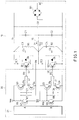
- FIG. 1 shows a circuitry of the power transistor drive circuit of an electromagnetic induction heating device, according to the present invention.
- FIG. 2 shows a wave form diagram of some of connection points of the circuitry as shown in FIG. 1.
- a power transistor driving circuit embodied in the present invention comprises an induction coil circuit 10 and a drive circuit 20.
- the induction coil circuit 10 is composed of a bridge-type rectifier B1 serving to rectify the alternating current to the direct current.
- the rectifier B1 is connected via a filtering capacitance CO with an oscillating circuit made up of an induction coil 15, capacitances C1, C2, C3, C4, C5, C6, and resistances R1 and R2.
- Two power transistors Q1 and Q2 are insulated gate bipolar transistors and are connected in series with the oscillating circuit.
- the drive circuit 20 are connected with the gates G1 and G2 of the two power transistors Q1 and Q2.
- the induction switching circuit 10 of the present invention is similar to that of the prior art.
- the drive circuit 20 comprises a switching circuit 21, which serves to send out the alternating high-low signal via two connection points A and B, as shown in FIG. 2.
- the connection point A is connected with the driving circuit made up of transistors Q3, Q4, Q7, resistances R3, R4, R7, R9, the capacitance C7, and the inductance L1, with its output end being connected with the gate G1 of the power transistor Q1 for turning the power transistor Q1 on or off.
- the connection point B is connected with the driving circuit made up of transistors Q5, Q6, Q8, the resistances R5, R6, R8, R10, the capacitance C8, and the inductance L2, with its output end being connected with the gate G2 of the power transistor Q2 for turning the power transistor Q2 on or off.
- the drive circuit 20 serves to regulate the ON/OFF switching motions of the two power transistors Q1 and Q2.
- the transistor Q3 of the drive circuit 20 of the present invention is of a NPN type and is provided with an emitter E3 which is connected with one end of the resistance R4. Another end of the resistance R4 is connected with the resistance R3 and an inductance L1 which is in turn connected at another end thereof with an emitter E4 of the transistor Q4 of the PNP type.
- a quick switching circuit is formed by the transistors Q3 and Q4, the resistances R3 and R4, and the inductance L1.
- another quick switching circuit is formed by the transistors Q5 and Q6 whose emitters E5 and E6 are connected in series with the resistance R6 and the inductance L2.
- a transient negative voltage is produced by these two quick switching circuits by means of the inductances L1 and L2 respectively at the time when the power transistors Q1 and Q2 are turned off.
- the turn-off time is shortened by the accelerated reverse flow of the emitting currents of the power transistors Q1 and Q2.
- a transient negative voltage Va is produced by virtue of the fact that VG1 is changed from a high potential to a low potential. In other words, the difference in potential between the emitter E1 and the gate G1 is increased so as to accelerate the reverse flow of the emitting current of the power transistor.
- the turn-off time t1 of the power transistor is so shortened that the switching power loss of the power transistor Q1 is reduced.
- a transient negative voltage vb is produced in the process in which VG2 is changed from a high potential to a low potential at the time when the power transistor Q2 is turned off.
- the difference in potential between the emitter E2 and the gate G2 is so increased as to accelerate the reverse flow of the emitting current of the power transistor Q2.
- the turn-off time t2 of the power transistor Q2 is therefore so shortened that the switching power loss of the power transistor Q2 is reduced.
- the gate of the power transistor of the power transistor driving circuit of the present invention is connected with the quick switching circuit so as to shorten the switching time to reduce the switching power loss of the power transistor. As a result, less heat is generated by the power transistor.
- the power transistor driving circuit of the present invention can be made economically in view of the fact that the power transistors Q1 and Q2 have a relatively small collect loss, a small size, and an excellent heat-radiating effect. The service life span of the power elements of the present invention is prolonged effectively. It is therefore readily apparent that an electromagnetic induction heating device equipped with the power transistor driving circuit of the present invention is durable and less vulnerable to breakdown.
Landscapes
- Physics & Mathematics (AREA)
- Electromagnetism (AREA)
- General Induction Heating (AREA)
- Inverter Devices (AREA)
Priority Applications (2)
| Application Number | Priority Date | Filing Date | Title |
|---|---|---|---|
| EP94300927A EP0666703A1 (fr) | 1994-02-08 | 1994-02-08 | Circuit de commande pour transistor de puissance pour appareil de chauffage par induction |
| US08/198,305 US5397878A (en) | 1994-02-08 | 1994-02-18 | Powder transistor driving circuit of electromagnetic induction heating device |
Applications Claiming Priority (2)
| Application Number | Priority Date | Filing Date | Title |
|---|---|---|---|
| EP94300927A EP0666703A1 (fr) | 1994-02-08 | 1994-02-08 | Circuit de commande pour transistor de puissance pour appareil de chauffage par induction |
| US08/198,305 US5397878A (en) | 1994-02-08 | 1994-02-18 | Powder transistor driving circuit of electromagnetic induction heating device |
Publications (1)
| Publication Number | Publication Date |
|---|---|
| EP0666703A1 true EP0666703A1 (fr) | 1995-08-09 |
Family
ID=26136919
Family Applications (1)
| Application Number | Title | Priority Date | Filing Date |
|---|---|---|---|
| EP94300927A Withdrawn EP0666703A1 (fr) | 1994-02-08 | 1994-02-08 | Circuit de commande pour transistor de puissance pour appareil de chauffage par induction |
Country Status (2)
| Country | Link |
|---|---|
| US (1) | US5397878A (fr) |
| EP (1) | EP0666703A1 (fr) |
Families Citing this family (16)
| Publication number | Priority date | Publication date | Assignee | Title |
|---|---|---|---|---|
| JPH07506478A (ja) * | 1992-05-07 | 1995-07-13 | シーメンス ニクスドルフ インフオルマチオーンスジステーメ アクチエンゲゼルシヤフト | Mos電界効果トランジスタを制御する回路装置 |
| US5532631A (en) * | 1994-11-17 | 1996-07-02 | Vtc Inc. | Active pull-down write driver for three-terminal inductive load |
| KR0138306B1 (ko) * | 1994-12-14 | 1998-06-15 | 김광호 | 영전압 스위칭 제어회로 |
| US5838185A (en) * | 1996-03-25 | 1998-11-17 | International Rectifier Corporation | Multiple individual Kelvin emitter connections to reduce current flow through parasitic diode |
| US6172550B1 (en) * | 1996-08-16 | 2001-01-09 | American Superconducting Corporation | Cryogenically-cooled switching circuit |
| US6414391B1 (en) | 1998-06-30 | 2002-07-02 | Micron Technology, Inc. | Module assembly for stacked BGA packages with a common bus bar in the assembly |
| JP3711257B2 (ja) * | 2001-10-30 | 2005-11-02 | 三菱電機株式会社 | 電力用半導体装置 |
| JP2003324937A (ja) * | 2002-05-09 | 2003-11-14 | Mitsubishi Electric Corp | 駆動装置 |
| US6977492B2 (en) * | 2002-07-10 | 2005-12-20 | Marvell World Trade Ltd. | Output regulator |
| JP2007028278A (ja) * | 2005-07-19 | 2007-02-01 | Denso Corp | 駆動回路 |
| USD558913S1 (en) | 2006-06-15 | 2008-01-01 | S.C. Johnson & Son, Inc. | Combination light object and base |
| JP5197658B2 (ja) * | 2010-03-10 | 2013-05-15 | 株式会社東芝 | 駆動回路 |
| CN102802289B (zh) * | 2012-07-30 | 2014-07-09 | 东莞市精诚电能设备有限公司 | 基于数字信号处理的电磁感应加热控制电路 |
| US9948289B2 (en) * | 2015-06-02 | 2018-04-17 | Infineon Technologies Austria Ag | System and method for a gate driver |
| US9994110B2 (en) * | 2016-08-30 | 2018-06-12 | Ford Global Technologies, Llc | Dual gate solid state devices to reduce switching loss |
| US11206016B2 (en) * | 2019-09-27 | 2021-12-21 | Analog Devices International Unlimited Company | Gate driver with pulsed gate slew control |
Citations (4)
| Publication number | Priority date | Publication date | Assignee | Title |
|---|---|---|---|---|
| EP0146479A2 (fr) * | 1983-12-20 | 1985-06-26 | FAIRCHILD CAMERA & INSTRUMENT CORPORATION | Méthode et appareil pour réduire le temps d'emmagasinage dans un transistor saturé |
| DE4110633A1 (de) * | 1990-04-02 | 1991-10-17 | Mitsubishi Electric Corp | Gate-treiberschaltung fuer eine isolierte gate-halbleitervorrichtung und blitzlichtsteuerung, welche die schaltung verwendet |
| JPH04251575A (ja) * | 1991-01-09 | 1992-09-07 | Wako Electric Co Ltd | インバ―タ回路 |
| US5204504A (en) * | 1988-08-26 | 1993-04-20 | Kabushiki Kaisha Toshiba | High-frequency heating apparatus including ringing effect suppressor for switching element |
Family Cites Families (9)
| Publication number | Priority date | Publication date | Assignee | Title |
|---|---|---|---|---|
| US4473732A (en) * | 1981-01-07 | 1984-09-25 | General Electric Company | Power circuit for induction cooking |
| JPS5878386A (ja) * | 1981-11-04 | 1983-05-11 | 松下電器産業株式会社 | 誘導加熱用インバ−タ装置 |
| GB2108786B (en) * | 1981-11-05 | 1985-12-11 | Sanyo Electric Co | Induction heating apparatus |
| DE3724043C2 (de) * | 1987-03-20 | 1996-10-17 | Tem Electromenager S A | Wechselrichter zur Speisung eines Verbrauchers mit einer induktiven Komponente |
| US4937470A (en) * | 1988-05-23 | 1990-06-26 | Zeiler Kenneth T | Driver circuit for power transistors |
| US4873460A (en) * | 1988-11-16 | 1989-10-10 | California Institute Of Technology | Monolithic transistor gate energy recovery system |
| US4983865A (en) * | 1989-01-25 | 1991-01-08 | Pacific Monolithics | High speed switch matrix |
| JP2682202B2 (ja) * | 1990-06-08 | 1997-11-26 | 日本電気株式会社 | 電界効果トランジスタを用いた整流回路 |
| US5276357A (en) * | 1992-09-01 | 1994-01-04 | Broadcast Electronics, Inc. | High efficiency quasi-square wave drive circuit for switching power amplifiers |
-
1994
- 1994-02-08 EP EP94300927A patent/EP0666703A1/fr not_active Withdrawn
- 1994-02-18 US US08/198,305 patent/US5397878A/en not_active Expired - Fee Related
Patent Citations (4)
| Publication number | Priority date | Publication date | Assignee | Title |
|---|---|---|---|---|
| EP0146479A2 (fr) * | 1983-12-20 | 1985-06-26 | FAIRCHILD CAMERA & INSTRUMENT CORPORATION | Méthode et appareil pour réduire le temps d'emmagasinage dans un transistor saturé |
| US5204504A (en) * | 1988-08-26 | 1993-04-20 | Kabushiki Kaisha Toshiba | High-frequency heating apparatus including ringing effect suppressor for switching element |
| DE4110633A1 (de) * | 1990-04-02 | 1991-10-17 | Mitsubishi Electric Corp | Gate-treiberschaltung fuer eine isolierte gate-halbleitervorrichtung und blitzlichtsteuerung, welche die schaltung verwendet |
| JPH04251575A (ja) * | 1991-01-09 | 1992-09-07 | Wako Electric Co Ltd | インバ―タ回路 |
Non-Patent Citations (1)
| Title |
|---|
| PATENT ABSTRACTS OF JAPAN vol. 17, no. 28 (E - 1308) 19 January 1993 (1993-01-19) * |
Also Published As
| Publication number | Publication date |
|---|---|
| US5397878A (en) | 1995-03-14 |
Similar Documents
| Publication | Publication Date | Title |
|---|---|---|
| US5397878A (en) | Powder transistor driving circuit of electromagnetic induction heating device | |
| EP3297396B1 (fr) | Dispositif de chauffage électromagnétique et son circuit de commande de chauffage, et procédé de commande de chauffage basse puissance | |
| EP1386390B1 (fr) | Circuit amplificateur haute frequence a commande independante du courant de repos et de l'impedance de polarisation | |
| JPH07222493A (ja) | 電力用電子機器における直流アクチュエータの制御装置 | |
| JP3409994B2 (ja) | 自己消弧形素子駆動回路 | |
| US6256211B1 (en) | Circuit device for driving an a.c. electric load | |
| KR0138667B1 (ko) | 전력증폭기 | |
| US6828748B2 (en) | Speed control circuit for a brushless dc motor | |
| JPS63185220A (ja) | カスコ−ド形BiMOSの駆動回路 | |
| US4859927A (en) | Power supply with improved switching regulator | |
| US4371918A (en) | High efficiency push-pull saturation converter | |
| US6650526B2 (en) | Demagnetizing circuit | |
| JP3964912B2 (ja) | 突入電流低減回路 | |
| Sherman | Class D amplifiers provide high efficiency for audio systems | |
| JPH07118777B2 (ja) | 誘導性負荷を駆動する回路および方法 | |
| CN110107593B (zh) | 无偏置磁轴承线圈控制电路及控制方法 | |
| JPS60119092A (ja) | 誘導加熱調理器 | |
| JPH06284719A (ja) | 高周波スイッチング電圧変換回路 | |
| JP4136349B2 (ja) | 自励発振回路 | |
| JP3993572B2 (ja) | ドライバ回路 | |
| KR100361841B1 (ko) | 전압제어 발진기의 초크길이 조절회로 | |
| JP3044257B2 (ja) | スイッチング素子の駆動装置 | |
| JPS59219021A (ja) | スイッチング・レギュレータ | |
| JP2009260659A (ja) | 電源装置およびその駆動方法 | |
| JPS5848387A (ja) | 誘導加熱装置 |
Legal Events
| Date | Code | Title | Description |
|---|---|---|---|
| PUAI | Public reference made under article 153(3) epc to a published international application that has entered the european phase |
Free format text: ORIGINAL CODE: 0009012 |
|
| AK | Designated contracting states |
Kind code of ref document: A1 Designated state(s): AT BE CH DE DK ES FR GB GR IE IT LI NL PT SE |
|
| 17P | Request for examination filed |
Effective date: 19960108 |
|
| RAP1 | Party data changed (applicant data changed or rights of an application transferred) |
Owner name: HUANG, WEN-LIANG |
|
| STAA | Information on the status of an ep patent application or granted ep patent |
Free format text: STATUS: THE APPLICATION IS DEEMED TO BE WITHDRAWN |
|
| 18D | Application deemed to be withdrawn |
Effective date: 19990901 |