EP0666968B1 - ENSEMBLE REDUCTEUR EPICYCLOiDAL - Google Patents
ENSEMBLE REDUCTEUR EPICYCLOiDAL Download PDFInfo
- Publication number
- EP0666968B1 EP0666968B1 EP93923544A EP93923544A EP0666968B1 EP 0666968 B1 EP0666968 B1 EP 0666968B1 EP 93923544 A EP93923544 A EP 93923544A EP 93923544 A EP93923544 A EP 93923544A EP 0666968 B1 EP0666968 B1 EP 0666968B1
- Authority
- EP
- European Patent Office
- Prior art keywords
- case
- reduction unit
- planet gear
- planet
- epicycloidal
- Prior art date
- Legal status (The legal status is an assumption and is not a legal conclusion. Google has not performed a legal analysis and makes no representation as to the accuracy of the status listed.)
- Expired - Lifetime
Links
- 238000005096 rolling process Methods 0.000 claims description 3
- 230000004323 axial length Effects 0.000 abstract description 2
- 230000008878 coupling Effects 0.000 description 5
- 238000010168 coupling process Methods 0.000 description 5
- 238000005859 coupling reaction Methods 0.000 description 5
- 238000010276 construction Methods 0.000 description 4
- 230000000717 retained effect Effects 0.000 description 2
- 230000005540 biological transmission Effects 0.000 description 1
- 230000013011 mating Effects 0.000 description 1
Images
Classifications
-
- F—MECHANICAL ENGINEERING; LIGHTING; HEATING; WEAPONS; BLASTING
- F16—ENGINEERING ELEMENTS AND UNITS; GENERAL MEASURES FOR PRODUCING AND MAINTAINING EFFECTIVE FUNCTIONING OF MACHINES OR INSTALLATIONS; THERMAL INSULATION IN GENERAL
- F16H—GEARING
- F16H57/00—General details of gearing
- F16H57/02—Gearboxes; Mounting gearing therein
- F16H57/021—Shaft support structures, e.g. partition walls, bearing eyes, casing walls or covers with bearings
-
- F—MECHANICAL ENGINEERING; LIGHTING; HEATING; WEAPONS; BLASTING
- F16—ENGINEERING ELEMENTS AND UNITS; GENERAL MEASURES FOR PRODUCING AND MAINTAINING EFFECTIVE FUNCTIONING OF MACHINES OR INSTALLATIONS; THERMAL INSULATION IN GENERAL
- F16H—GEARING
- F16H1/00—Toothed gearings for conveying rotary motion
- F16H1/28—Toothed gearings for conveying rotary motion with gears having orbital motion
-
- F—MECHANICAL ENGINEERING; LIGHTING; HEATING; WEAPONS; BLASTING
- F16—ENGINEERING ELEMENTS AND UNITS; GENERAL MEASURES FOR PRODUCING AND MAINTAINING EFFECTIVE FUNCTIONING OF MACHINES OR INSTALLATIONS; THERMAL INSULATION IN GENERAL
- F16H—GEARING
- F16H57/00—General details of gearing
- F16H57/08—General details of gearing of gearings with members having orbital motion
- F16H57/082—Planet carriers
-
- F—MECHANICAL ENGINEERING; LIGHTING; HEATING; WEAPONS; BLASTING
- F16—ENGINEERING ELEMENTS AND UNITS; GENERAL MEASURES FOR PRODUCING AND MAINTAINING EFFECTIVE FUNCTIONING OF MACHINES OR INSTALLATIONS; THERMAL INSULATION IN GENERAL
- F16H—GEARING
- F16H1/00—Toothed gearings for conveying rotary motion
- F16H1/28—Toothed gearings for conveying rotary motion with gears having orbital motion
- F16H1/46—Systems consisting of a plurality of gear trains each with orbital gears, i.e. systems having three or more central gears
Definitions
- This invention relates to an epicycloidal gear reduction unit comprising:
- reduction unit is used to denote a power transmission unit effective to step down or up the rotational speed of a driven shaft relative to a drive shaft.
- Reduction units with the above-noted features have been extensively known in the relevant art, and reference can be made, for example, to the following technical literature: Gerit "Riduttori epicicloidali a gioco ridotto alpha”, published by Gerit S.p.A. of Milan, Italy, 1991; and Transmital Bonfiglioli "Riduttori epicicloidali Serie 300", published by Transmital Bonfiglioli S.p.A. of Forl ⁇ , Italy, 1988.
- portion of the reduction unit which is to carry the aforesaid shaft to have an axial length which exceeds that of the portion enclosing the epicycloidal gearing.
- the technical problem addressed by this invention is to provide an epicycloidal gear reduction unit which is conceived, both in construction and performance, to minimize its bulk, especially along the axial direction.
- a reduction unit as indicated in the preamble being characterized in that said planet gear carrier comprises a single disc-shaped member mounted at one axial end of the unit and having a plurality of planet gear stub shafts projecting therefrom toward the other axial end of the unit, and in that said bearing has a first and a second track formed respectively directly around the radially outermost periphery of said disc-shaped member and in the part of said case facing said disc-shaped member.
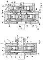
- FIG. 1 Shown in Figure 1 is a first embodiment of an epicycloidal gear reduction unit according to this invention; this first embodiment is generally indicated at 1.
- the reduction unit 1 comprises a case or casing 2 formed of two flanged members 3, 4 with a ring gear 5 therebetween.
- the flanged members 3, 4 are clamped to the ring gear 5 in a conventional way using screws, tie rods, brackets, or the like fastening means, not shown.
- the ring gear 5 has, in a manner known per se, an internal toothing 6 and is a part of an epicycloidal mechanism also comprising a sun gear 7 and plural planet gears 8.
- the sun gear 7 is keyed to the end of a shaft 9, being referred to as the fast-motion shaft of the reduction unit 1 and supported on a tubular hub 11 of the flanged member 3 through bearings 10a,b.
- the planet gears 8 are mounted idle on a planet gear carrier 12 which includes respective stub shafts 13 whereon the planet gears are journalled through intervening bearings 14; the planet gear carrier 12 includes a disc-shaped member 15 carrying said stub shafts 13.
- the disc-shaped member 15 is rigid with a shaft 16, being referred to as the slow-motion shaft of the reduction unit and formed of preference integrally therewith. Both shafts are provided, moreover, with oil seals 22.
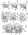
- shafts 9, 16, as the power take-off means of the reduction unit 1, may be any desired configurations; examples of such configurations, well known to the skilled ones in the art and related to the power take-off means which correspond to the shaft 16, are depicted in Figures 7 to 9 showing respectively a grooved profile female coupling member 16a, a keyed coupling member 16b, and a member 16c for direct coupling to a ring gear 16d, for example.
- the slow-motion shaft 16 with the planet carrier 12 is supported on the case 2 by means of a rolling bearing 17 of the ball type.
- the balls are designated 18 and held in respective tracks 19, 20.
- Track 19 is formed directly around the periphery of the disc-shaped member 15.
- Track 20 is formed half on the flanged member 4 and half on the ring gear 5, in the interconnect region thereof.
- the bearing 17a has balls 18 and two races, respectively an inner race 23 and an outer race 24 formed with ball tracks 19 and 20, respectively.
- the bearing races 23, 24 comprise two matched half-races each, 23a,b and 24a,b, respectively.
- the inner race 23 is retained in a bearing block 25 formed on the periphery of the disc-shaped member 15, between a shoulder 26 and a snap ring 27.
- the outer race 24 is retained in a bearing block 28 formed on the mating surfaces of the flanged member 4 and the ring gear 5.
- the bearing 17b is a plain bearing having a bushing 30 with a square cross-sectional shape and pairs of adjacent sides 30a,b and 30c,d, respectively, held in rubbing contact with respective V-shaped tracks 19 and 20 on the disc-shaped member and the reduction unit casing.
- the bearing 17c is of the type with a double tier of rollers 31, 32 fitted between respective tracks 31a,b and 32a,b.
- the tracks 31a, 32a are formed around the periphery of the disc-shaped member 15 and the tracks 31b, 32b are formed on the respective facing surfaces of the ring gear 5 and the flanged member 4.
- FIG. 2 Shown in Figure 2 is a cascaded reduction system, generally indicated at 50, which comprises plural reduction units (two, respectively referenced 1A and 1B, in this example) arranged. in series with one another.
- the components of each reduction unit 1A,B are basically the same as detailed in the description of the example shown in Figure 1, to which reference is directed. Accordingly, similar parts will be denoted by the same reference numerals with an "A" suffix added for the components of reduction unit 1A and a "B" suffix added for the components of reduction unit 1B.
- a major advantage of the cascaded reduction system 50 is its compact axial dimension, despite the fact that the individual epicycloidal reduction units which compose it are all of the type with a supported planet gear carrier (in bearings 17a,b, respectively, in the example considered).
- FIG. 3 shows a further embodiment of the invention, generally indicated at 60, which is specially useful in applications requiring that the planet gear carrier be held stationary and the casing rotated.
- Typical applications of this kind are, for instance, the constructions of rotary drum capstans and vehicle wheel hubs.
- similar parts carry the same reference numerals as in the previous embodiments.
- the ring gear 5 is included between a cover 61 and a flanged member 62 having a first flange 63 which extends radially inwards and a second flange 64 which extends radially outwards. Attached to the second flange is a driven member 64a, such as a wheel flange.
- the planet gear carrier 12 has, additionally to the bearing 17, two coaxial ring-shaped surfaces 65, 66 and a central cylindrical passage 67. Arranged between the ring-shaped surface 65 and the first flange 63 is an oil seal 68. A stationary part 69 is attached to the planet carrier 12 at the location of a shoulder 70 between the surfaces 65, 66. Also provided is a motor 71 having a motor casing attached to the planet carrier 12 and a motor shaft 72 coupled, as by means of a sleeve coupling 73 and respective splined couplings 74a,b, to the fast-motion shaft 9 made rigid with the sun gear 7.
Landscapes
- Engineering & Computer Science (AREA)
- General Engineering & Computer Science (AREA)
- Mechanical Engineering (AREA)
- Retarders (AREA)
- General Details Of Gearings (AREA)
- Valve Device For Special Equipments (AREA)
- Structure Of Transmissions (AREA)
Claims (3)
- Réducteur épicycloïdal, comprenant :un carter (2),un porte-satellites (12) monté afin qu'il puisse tourner dans le carter,une prise de force (16) qui présente une rigidité en rotation avec le porte-satellites, etun palier (17) du type à éléments roulants placé entre le porte-satellites (12) et le carter (2) afin qu'il supporte l'ensemble formé par la prise de force et le porte-satellites, caractérisé en ce que le porte-satellites (12) comporte un seul organe (15) en forme de disque monté à une première extrémité axiale du réducteur et ayant plusieurs arbres rectilignes (13) de support de pignons satellites dépassant vers l'autre extrémité axiale du réducteur, et en ce que le palier comporte une première et une seconde voie (19, 20) formées respectivement autour de la périphérie radialement la plus externe de l'organe en forme de disque et dans la partie du carter (2) tournée vers l'organe en forme de disque.
- Réducteur épicycloidal selon la revendication 1, dans lequel le carter (2) comporte deux parties (4, 5) raccordées l'une à l'autre au niveau de la seconde voie (20), la seconde voie étant formée partiellement sur l'une des parties et partiellement sur l'autre des parties (4, 5).
- Réducteur épicycloïdal selon la revendication 2, dans lequel l'une des parties de carter comporte une couronne dentée (5) du réducteur qui est en prise avec les pignons satellites (8).
Applications Claiming Priority (3)
| Application Number | Priority Date | Filing Date | Title |
|---|---|---|---|
| ITPD920195A IT1259180B (it) | 1992-11-04 | 1992-11-04 | Riduttore epicicloidale perfezionato |
| ITPD920195 | 1992-11-04 | ||
| PCT/EP1993/002942 WO1994010478A1 (fr) | 1992-11-04 | 1993-10-25 | Ensemble reducteur epicycloïdal |
Publications (2)
| Publication Number | Publication Date |
|---|---|
| EP0666968A1 EP0666968A1 (fr) | 1995-08-16 |
| EP0666968B1 true EP0666968B1 (fr) | 1996-11-20 |
Family
ID=11390087
Family Applications (1)
| Application Number | Title | Priority Date | Filing Date |
|---|---|---|---|
| EP93923544A Expired - Lifetime EP0666968B1 (fr) | 1992-11-04 | 1993-10-25 | ENSEMBLE REDUCTEUR EPICYCLOiDAL |
Country Status (7)
| Country | Link |
|---|---|
| EP (1) | EP0666968B1 (fr) |
| AT (1) | ATE145456T1 (fr) |
| AU (1) | AU5337694A (fr) |
| DE (1) | DE69306123T2 (fr) |
| ES (1) | ES2096952T3 (fr) |
| IT (1) | IT1259180B (fr) |
| WO (1) | WO1994010478A1 (fr) |
Cited By (1)
| Publication number | Priority date | Publication date | Assignee | Title |
|---|---|---|---|---|
| EP4187126A1 (fr) * | 2021-11-25 | 2023-05-31 | Delta Dore | Système réducteur à engrenages et bagues dentées pour un moteur d'un ensemble occultant où le système réducteur présente un bruit de fonctionnement réduit |
Families Citing this family (4)
| Publication number | Priority date | Publication date | Assignee | Title |
|---|---|---|---|---|
| DE19913780A1 (de) * | 1999-03-26 | 2000-09-28 | Zahnradfabrik Friedrichshafen | Planetengetriebe |
| ITMI20100104A1 (it) * | 2010-01-27 | 2011-07-28 | Apex Dynamics Inc | Ingranaggio planetario riduttore di velocita'. |
| CN110254508B (zh) * | 2019-06-29 | 2025-01-10 | 华南理工大学 | 一种可变传动比的车辆主动转向传动装置、汽车 |
| JP7725336B2 (ja) * | 2021-10-26 | 2025-08-19 | 株式会社マキタ | 打ち込み工具 |
Family Cites Families (5)
| Publication number | Priority date | Publication date | Assignee | Title |
|---|---|---|---|---|
| US2765669A (en) * | 1955-04-08 | 1956-10-09 | Tangen Anthony | Bearing construction for helical gear transmission |
| IT8021989V0 (it) * | 1980-06-06 | 1980-06-06 | Same Spa | Mozzo ruota con riduttore epicicloidale, particolarmente destinato all'assale anteriore di trattrici. |
| US4583420A (en) * | 1984-10-11 | 1986-04-22 | Miley Bradford A | Handwheel actuated machine tool mechanism |
| DE3634894A1 (de) * | 1986-10-14 | 1987-12-17 | Wittenstein Manfred | Antriebsvorrichtung mit einem elektromotor und einem diesem vorgeschalteten getriebe in einem gemeinsamen gehaeuse |
| JPH0450538A (ja) * | 1990-06-15 | 1992-02-19 | Takashi Takahashi | 多段遊星型変速装置 |
-
1992
- 1992-11-04 IT ITPD920195A patent/IT1259180B/it active IP Right Grant
-
1993
- 1993-10-25 AU AU53376/94A patent/AU5337694A/en not_active Abandoned
- 1993-10-25 ES ES93923544T patent/ES2096952T3/es not_active Expired - Lifetime
- 1993-10-25 DE DE69306123T patent/DE69306123T2/de not_active Expired - Fee Related
- 1993-10-25 EP EP93923544A patent/EP0666968B1/fr not_active Expired - Lifetime
- 1993-10-25 WO PCT/EP1993/002942 patent/WO1994010478A1/fr not_active Ceased
- 1993-10-25 AT AT93923544T patent/ATE145456T1/de not_active IP Right Cessation
Cited By (1)
| Publication number | Priority date | Publication date | Assignee | Title |
|---|---|---|---|---|
| EP4187126A1 (fr) * | 2021-11-25 | 2023-05-31 | Delta Dore | Système réducteur à engrenages et bagues dentées pour un moteur d'un ensemble occultant où le système réducteur présente un bruit de fonctionnement réduit |
Also Published As
| Publication number | Publication date |
|---|---|
| DE69306123T2 (de) | 1997-06-12 |
| WO1994010478A1 (fr) | 1994-05-11 |
| DE69306123D1 (de) | 1997-01-02 |
| ITPD920195A0 (it) | 1992-11-04 |
| IT1259180B (it) | 1996-03-11 |
| AU5337694A (en) | 1994-05-24 |
| ES2096952T3 (es) | 1997-03-16 |
| ITPD920195A1 (it) | 1994-05-04 |
| EP0666968A1 (fr) | 1995-08-16 |
| ATE145456T1 (de) | 1996-12-15 |
Similar Documents
| Publication | Publication Date | Title |
|---|---|---|
| AU2019201928B2 (en) | Epicyclic gearbox | |
| US6814684B2 (en) | Planetary gear | |
| CN109109640B (zh) | 一种同轴式独立电驱桥及电动汽车 | |
| US4391163A (en) | Planetary gear assembly | |
| US4380274A (en) | Holding a planetary gear carrier relative to an axle | |
| US5087230A (en) | Drive transmissions | |
| US4610182A (en) | Planetary gear arranged in a gear housing between a jet engine and an electrical engine | |
| US4133344A (en) | Power transmission for self-propelled irrigation system | |
| EP2068036B1 (fr) | Engrenage réducteur | |
| JPH0274401A (ja) | 車両用全浮動式車軸アセンブリ | |
| US4392396A (en) | Final drive assembly for vehicles | |
| JPS642823B2 (fr) | ||
| US6290625B1 (en) | Small backlash planetary gear assembly | |
| EP1210532B1 (fr) | Train d'engrenages a repartition de puissance dans une transmission planetaire | |
| EP0666968B1 (fr) | ENSEMBLE REDUCTEUR EPICYCLOiDAL | |
| US4770062A (en) | Planetary gear apparatus | |
| EP1239191B1 (fr) | Unité de différentiel | |
| CN120946784A (zh) | 关节模组和机器人 | |
| US6645107B2 (en) | Epicycle reduction gear having a built-in hydraulic motor | |
| US12523284B2 (en) | Transmission mechanism for rotary joint, robot joint and robot | |
| US7004877B2 (en) | Variable speed transmission arrangement with an infinitely variable toroidal drive and a summing gear set of the planet wheel type | |
| EP4075020A1 (fr) | Jeu d'engrenage planétaire | |
| JP2555035Y2 (ja) | プラネタリギヤユニット | |
| US11529864B2 (en) | Drive device for electric vehicle and electric vehicle | |
| JP2626116B2 (ja) | 航空機用減速機 |
Legal Events
| Date | Code | Title | Description |
|---|---|---|---|
| PUAI | Public reference made under article 153(3) epc to a published international application that has entered the european phase |
Free format text: ORIGINAL CODE: 0009012 |
|
| 17P | Request for examination filed |
Effective date: 19950420 |
|
| AK | Designated contracting states |
Kind code of ref document: A1 Designated state(s): AT BE DE ES FR GB IT NL SE |
|
| GRAG | Despatch of communication of intention to grant |
Free format text: ORIGINAL CODE: EPIDOS AGRA |
|
| 17Q | First examination report despatched |
Effective date: 19960130 |
|
| GRAH | Despatch of communication of intention to grant a patent |
Free format text: ORIGINAL CODE: EPIDOS IGRA |
|
| GRAH | Despatch of communication of intention to grant a patent |
Free format text: ORIGINAL CODE: EPIDOS IGRA |
|
| GRAA | (expected) grant |
Free format text: ORIGINAL CODE: 0009210 |
|
| AK | Designated contracting states |
Kind code of ref document: B1 Designated state(s): AT BE DE ES FR GB IT NL SE |
|
| REF | Corresponds to: |
Ref document number: 145456 Country of ref document: AT Date of ref document: 19961215 Kind code of ref document: T |
|
| REF | Corresponds to: |
Ref document number: 69306123 Country of ref document: DE Date of ref document: 19970102 |
|
| ITF | It: translation for a ep patent filed | ||
| REG | Reference to a national code |
Ref country code: ES Ref legal event code: FG2A Ref document number: 2096952 Country of ref document: ES Kind code of ref document: T3 |
|
| ET | Fr: translation filed | ||
| PLBE | No opposition filed within time limit |
Free format text: ORIGINAL CODE: 0009261 |
|
| STAA | Information on the status of an ep patent application or granted ep patent |
Free format text: STATUS: NO OPPOSITION FILED WITHIN TIME LIMIT |
|
| 26N | No opposition filed | ||
| PGFP | Annual fee paid to national office [announced via postgrant information from national office to epo] |
Ref country code: SE Payment date: 20000831 Year of fee payment: 8 |
|
| PGFP | Annual fee paid to national office [announced via postgrant information from national office to epo] |
Ref country code: AT Payment date: 20000911 Year of fee payment: 8 |
|
| PGFP | Annual fee paid to national office [announced via postgrant information from national office to epo] |
Ref country code: GB Payment date: 20000919 Year of fee payment: 8 |
|
| PGFP | Annual fee paid to national office [announced via postgrant information from national office to epo] |
Ref country code: NL Payment date: 20000925 Year of fee payment: 8 Ref country code: DE Payment date: 20000925 Year of fee payment: 8 |
|
| PGFP | Annual fee paid to national office [announced via postgrant information from national office to epo] |
Ref country code: BE Payment date: 20001016 Year of fee payment: 8 |
|
| PGFP | Annual fee paid to national office [announced via postgrant information from national office to epo] |
Ref country code: FR Payment date: 20001030 Year of fee payment: 8 Ref country code: ES Payment date: 20001030 Year of fee payment: 8 |
|
| PG25 | Lapsed in a contracting state [announced via postgrant information from national office to epo] |
Ref country code: GB Free format text: LAPSE BECAUSE OF NON-PAYMENT OF DUE FEES Effective date: 20011025 Ref country code: AT Free format text: LAPSE BECAUSE OF NON-PAYMENT OF DUE FEES Effective date: 20011025 |
|
| PG25 | Lapsed in a contracting state [announced via postgrant information from national office to epo] |
Ref country code: SE Free format text: LAPSE BECAUSE OF NON-PAYMENT OF DUE FEES Effective date: 20011026 Ref country code: ES Free format text: LAPSE BECAUSE OF NON-PAYMENT OF DUE FEES Effective date: 20011026 |
|
| PG25 | Lapsed in a contracting state [announced via postgrant information from national office to epo] |
Ref country code: BE Free format text: LAPSE BECAUSE OF NON-PAYMENT OF DUE FEES Effective date: 20011031 |
|
| REG | Reference to a national code |
Ref country code: GB Ref legal event code: IF02 |
|
| BERE | Be: lapsed |
Owner name: CASAROTTO G. & C. S.R.L. Effective date: 20011031 |
|
| PG25 | Lapsed in a contracting state [announced via postgrant information from national office to epo] |
Ref country code: NL Free format text: LAPSE BECAUSE OF NON-PAYMENT OF DUE FEES Effective date: 20020501 |
|
| EUG | Se: european patent has lapsed |
Ref document number: 93923544.6 |
|
| GBPC | Gb: european patent ceased through non-payment of renewal fee |
Effective date: 20011025 |
|
| PG25 | Lapsed in a contracting state [announced via postgrant information from national office to epo] |
Ref country code: FR Free format text: LAPSE BECAUSE OF NON-PAYMENT OF DUE FEES Effective date: 20020628 |
|
| NLV4 | Nl: lapsed or anulled due to non-payment of the annual fee |
Effective date: 20020501 |
|
| PG25 | Lapsed in a contracting state [announced via postgrant information from national office to epo] |
Ref country code: DE Free format text: LAPSE BECAUSE OF NON-PAYMENT OF DUE FEES Effective date: 20020702 |
|
| REG | Reference to a national code |
Ref country code: FR Ref legal event code: ST |
|
| REG | Reference to a national code |
Ref country code: ES Ref legal event code: FD2A Effective date: 20021113 |
|
| PG25 | Lapsed in a contracting state [announced via postgrant information from national office to epo] |
Ref country code: IT Free format text: LAPSE BECAUSE OF NON-PAYMENT OF DUE FEES;WARNING: LAPSES OF ITALIAN PATENTS WITH EFFECTIVE DATE BEFORE 2007 MAY HAVE OCCURRED AT ANY TIME BEFORE 2007. THE CORRECT EFFECTIVE DATE MAY BE DIFFERENT FROM THE ONE RECORDED. Effective date: 20051025 |