EP0667193A1 - Verfahren zur Herstellung falznahtloser Dosen - Google Patents
Verfahren zur Herstellung falznahtloser Dosen Download PDFInfo
- Publication number
- EP0667193A1 EP0667193A1 EP95300932A EP95300932A EP0667193A1 EP 0667193 A1 EP0667193 A1 EP 0667193A1 EP 95300932 A EP95300932 A EP 95300932A EP 95300932 A EP95300932 A EP 95300932A EP 0667193 A1 EP0667193 A1 EP 0667193A1
- Authority
- EP
- European Patent Office
- Prior art keywords
- ironing
- die
- annular
- working
- punch
- Prior art date
- Legal status (The legal status is an assumption and is not a legal conclusion. Google has not performed a legal analysis and makes no representation as to the accuracy of the status listed.)
- Granted
Links
- 238000000034 method Methods 0.000 title claims abstract description 63
- 238000010409 ironing Methods 0.000 claims abstract description 163
- 229910052751 metal Inorganic materials 0.000 claims abstract description 43
- 239000002184 metal Substances 0.000 claims abstract description 43
- 238000013459 approach Methods 0.000 claims description 67
- 239000000463 material Substances 0.000 claims description 15
- 230000009477 glass transition Effects 0.000 claims description 8
- 238000009826 distribution Methods 0.000 abstract description 5
- 238000012360 testing method Methods 0.000 description 46
- 238000005452 bending Methods 0.000 description 15
- 239000003973 paint Substances 0.000 description 12
- 239000000853 adhesive Substances 0.000 description 7
- 229920001577 copolymer Polymers 0.000 description 7
- XLYOFNOQVPJJNP-UHFFFAOYSA-N water Substances O XLYOFNOQVPJJNP-UHFFFAOYSA-N 0.000 description 6
- 229910000831 Steel Inorganic materials 0.000 description 5
- -1 polyethylene Polymers 0.000 description 5
- 239000010959 steel Substances 0.000 description 5
- 239000004593 Epoxy Substances 0.000 description 4
- 229910000576 Laminated steel Inorganic materials 0.000 description 4
- 238000010586 diagram Methods 0.000 description 4
- 238000002844 melting Methods 0.000 description 4
- 230000008018 melting Effects 0.000 description 4
- 230000002093 peripheral effect Effects 0.000 description 4
- 230000002087 whitening effect Effects 0.000 description 4
- BZHJMEDXRYGGRV-UHFFFAOYSA-N Vinyl chloride Chemical compound ClC=C BZHJMEDXRYGGRV-UHFFFAOYSA-N 0.000 description 3
- 230000008901 benefit Effects 0.000 description 3
- 238000010438 heat treatment Methods 0.000 description 3
- 239000000314 lubricant Substances 0.000 description 3
- 238000004519 manufacturing process Methods 0.000 description 3
- 239000012188 paraffin wax Substances 0.000 description 3
- 239000005029 tin-free steel Substances 0.000 description 3
- LLLVZDVNHNWSDS-UHFFFAOYSA-N 4-methylidene-3,5-dioxabicyclo[5.2.2]undeca-1(9),7,10-triene-2,6-dione Chemical compound C1(C2=CC=C(C(=O)OC(=C)O1)C=C2)=O LLLVZDVNHNWSDS-UHFFFAOYSA-N 0.000 description 2
- VGGSQFUCUMXWEO-UHFFFAOYSA-N Ethene Chemical compound C=C VGGSQFUCUMXWEO-UHFFFAOYSA-N 0.000 description 2
- 239000005977 Ethylene Substances 0.000 description 2
- 239000004698 Polyethylene Substances 0.000 description 2
- ZCDOYSPFYFSLEW-UHFFFAOYSA-N chromate(2-) Chemical compound [O-][Cr]([O-])(=O)=O ZCDOYSPFYFSLEW-UHFFFAOYSA-N 0.000 description 2
- 238000007796 conventional method Methods 0.000 description 2
- 238000001816 cooling Methods 0.000 description 2
- 230000003247 decreasing effect Effects 0.000 description 2
- 239000008157 edible vegetable oil Substances 0.000 description 2
- 230000005489 elastic deformation Effects 0.000 description 2
- 230000002708 enhancing effect Effects 0.000 description 2
- 239000010410 layer Substances 0.000 description 2
- 230000007246 mechanism Effects 0.000 description 2
- 229920000573 polyethylene Polymers 0.000 description 2
- 229920005672 polyolefin resin Polymers 0.000 description 2
- 230000009467 reduction Effects 0.000 description 2
- 238000005496 tempering Methods 0.000 description 2
- 239000001993 wax Substances 0.000 description 2
- 229910000838 Al alloy Inorganic materials 0.000 description 1
- 229920001634 Copolyester Polymers 0.000 description 1
- JOYRKODLDBILNP-UHFFFAOYSA-N Ethyl urethane Chemical compound CCOC(N)=O JOYRKODLDBILNP-UHFFFAOYSA-N 0.000 description 1
- JHWNWJKBPDFINM-UHFFFAOYSA-N Laurolactam Chemical compound O=C1CCCCCCCCCCCN1 JHWNWJKBPDFINM-UHFFFAOYSA-N 0.000 description 1
- 229920000571 Nylon 11 Polymers 0.000 description 1
- 229920000299 Nylon 12 Polymers 0.000 description 1
- 229920002292 Nylon 6 Polymers 0.000 description 1
- 229920002302 Nylon 6,6 Polymers 0.000 description 1
- 235000019482 Palm oil Nutrition 0.000 description 1
- ISWSIDIOOBJBQZ-UHFFFAOYSA-N Phenol Chemical compound OC1=CC=CC=C1 ISWSIDIOOBJBQZ-UHFFFAOYSA-N 0.000 description 1
- 239000004952 Polyamide Substances 0.000 description 1
- 229920001328 Polyvinylidene chloride Polymers 0.000 description 1
- XTXRWKRVRITETP-UHFFFAOYSA-N Vinyl acetate Chemical compound CC(=O)OC=C XTXRWKRVRITETP-UHFFFAOYSA-N 0.000 description 1
- 230000009471 action Effects 0.000 description 1
- 229910045601 alloy Inorganic materials 0.000 description 1
- 239000000956 alloy Substances 0.000 description 1
- 229910052782 aluminium Inorganic materials 0.000 description 1
- XAGFODPZIPBFFR-UHFFFAOYSA-N aluminium Chemical compound [Al] XAGFODPZIPBFFR-UHFFFAOYSA-N 0.000 description 1
- 235000013405 beer Nutrition 0.000 description 1
- 235000013361 beverage Nutrition 0.000 description 1
- 238000007664 blowing Methods 0.000 description 1
- 238000009924 canning Methods 0.000 description 1
- 235000014171 carbonated beverage Nutrition 0.000 description 1
- 239000011248 coating agent Substances 0.000 description 1
- 238000000576 coating method Methods 0.000 description 1
- 235000016213 coffee Nutrition 0.000 description 1
- 235000013353 coffee beverage Nutrition 0.000 description 1
- 230000000052 comparative effect Effects 0.000 description 1
- 230000000295 complement effect Effects 0.000 description 1
- 239000000470 constituent Substances 0.000 description 1
- 238000005336 cracking Methods 0.000 description 1
- 230000007547 defect Effects 0.000 description 1
- 230000006866 deterioration Effects 0.000 description 1
- 238000009820 dry lamination Methods 0.000 description 1
- 238000001035 drying Methods 0.000 description 1
- 230000000694 effects Effects 0.000 description 1
- 229920006332 epoxy adhesive Polymers 0.000 description 1
- 238000007765 extrusion coating Methods 0.000 description 1
- 235000013305 food Nutrition 0.000 description 1
- 235000015203 fruit juice Nutrition 0.000 description 1
- 229920000554 ionomer Polymers 0.000 description 1
- 229940057995 liquid paraffin Drugs 0.000 description 1
- 238000003754 machining Methods 0.000 description 1
- 239000002540 palm oil Substances 0.000 description 1
- 229920002647 polyamide Polymers 0.000 description 1
- 229920001707 polybutylene terephthalate Polymers 0.000 description 1
- 229920000728 polyester Polymers 0.000 description 1
- 239000004800 polyvinyl chloride Substances 0.000 description 1
- 229920000915 polyvinyl chloride Polymers 0.000 description 1
- 239000005033 polyvinylidene chloride Substances 0.000 description 1
- 125000002924 primary amino group Chemical group [H]N([H])* 0.000 description 1
- 238000011084 recovery Methods 0.000 description 1
- 230000003252 repetitive effect Effects 0.000 description 1
- 230000000630 rising effect Effects 0.000 description 1
- 239000002356 single layer Substances 0.000 description 1
- 229920003048 styrene butadiene rubber Polymers 0.000 description 1
- 229920003051 synthetic elastomer Polymers 0.000 description 1
- 239000005061 synthetic rubber Substances 0.000 description 1
- 229920001169 thermoplastic Polymers 0.000 description 1
- 229920005992 thermoplastic resin Polymers 0.000 description 1
- 229920001187 thermosetting polymer Polymers 0.000 description 1
- 239000004416 thermosoftening plastic Substances 0.000 description 1
- 238000012546 transfer Methods 0.000 description 1
- 125000000391 vinyl group Chemical group [H]C([*])=C([H])[H] 0.000 description 1
- 239000003871 white petrolatum Substances 0.000 description 1
- 230000037303 wrinkles Effects 0.000 description 1
Images







Classifications
-
- B—PERFORMING OPERATIONS; TRANSPORTING
- B21—MECHANICAL METAL-WORKING WITHOUT ESSENTIALLY REMOVING MATERIAL; PUNCHING METAL
- B21D—WORKING OR PROCESSING OF SHEET METAL OR METAL TUBES, RODS OR PROFILES WITHOUT ESSENTIALLY REMOVING MATERIAL; PUNCHING METAL
- B21D51/00—Making hollow objects
-
- B—PERFORMING OPERATIONS; TRANSPORTING
- B21—MECHANICAL METAL-WORKING WITHOUT ESSENTIALLY REMOVING MATERIAL; PUNCHING METAL
- B21D—WORKING OR PROCESSING OF SHEET METAL OR METAL TUBES, RODS OR PROFILES WITHOUT ESSENTIALLY REMOVING MATERIAL; PUNCHING METAL
- B21D22/00—Shaping without cutting, by stamping, spinning, or deep-drawing
- B21D22/20—Deep-drawing
- B21D22/28—Deep-drawing of cylindrical articles using consecutive dies
-
- B—PERFORMING OPERATIONS; TRANSPORTING
- B21—MECHANICAL METAL-WORKING WITHOUT ESSENTIALLY REMOVING MATERIAL; PUNCHING METAL
- B21D—WORKING OR PROCESSING OF SHEET METAL OR METAL TUBES, RODS OR PROFILES WITHOUT ESSENTIALLY REMOVING MATERIAL; PUNCHING METAL
- B21D51/00—Making hollow objects
- B21D51/16—Making hollow objects characterised by the use of the objects
- B21D51/26—Making hollow objects characterised by the use of the objects cans or tins; Closing same in a permanent manner
Definitions
- the present invention relates to a method of producing seamless cans for forming container bodies that are used for containing carbonated beverages, beer, coffee, fruit juices, etc.
- a method for producing relatively elongated seamless cans of which the thickness of the side wall is reduced by redraw-forming a draw-formed metal cup coated with an organic film using a die having a small radius of curvature at the working corner Japanese Laid-Open Patent Publications Nos. 258822/1989 and 155419/1991. According to this method, the thickness is reduced by bend-elongation accompanied, however, by problems as described below.
- An object of the present invention is to provide a method of producing relatively elongated seamless cans having a side wall portion of a reduced thickness from the metal cups of which the inner and outer surfaces are coated with an organic film, maintaining such advantages that a breaking limit is enhanced in reducing the thickness of the side wall portion, that the distribution of thickness of the side wall portion is controlled, and that the obtained seamless cans little permit the organic film to be deteriorated as represented by whitening when they are subjected to the subsequent working such as necking or the like.
- a method of producing seamless cans from metal cups made of a metal sheet of which the inner and outer surfaces are coated with an organic film comprising: using an annular die which has a horizontal surface, an annular working surface continuous to the horizontal surface, a working corner portion of a small radius of curvature at a boundary portion between the above two surfaces, and an ironing portion that protrudes most toward the inner side and is formed in said annular working surface; disposing said metal cup on said annular die; and inserting an annular blank holder in the metal cup, advancing a punch from the blank holder into the annular die while pushing the bottom portion of the metal cup by said blank holder onto the horizontal surface of the annular die, so as to pass the wall portion of the matel cup that is to be worked through space between the horizontal surface of the annular die and the blank holder and further through space between the punch and the annular die, whereby the thickness of the wall portion is reduced by bend-elongation at the working corner and is further reduced by the ironing at
- the bend-elongation (redraw working) by the working corner of the die and the ironing working are carried out through the same stroke using the same tool.
- a method of producing seamless cans from metal cups made of a metal sheet of which the inner and outer surfaces are coated with an organic film comprising: using an annular die which has a horizontal surface, an annular working surface continuous to the horizontal surface and a working corner portion of a small radius of curvature at a boundary portion between the above two surfaces; disposing said metal cup on said annular die; inserting an annular blank holder in the metal cup, advancing a first punch from the blank holder into the annular die while pushing the bottom portion of the metal cup by said blank holder onto the horizontal surface of the annular die, so as to pass the wall portion that is to be worked through space between the horizontal surface of the annular die and the blank holder and further through space between the first punch and the annular surface of the annular die, whereby the thickness of the wall portion is reduced by bend-elongation at the working corner to obtain a draw-formed cup; using an annular ironing die having an annular working surface and an ironing portion that protrudes most
- the redraw working and the ironing working are executed in two strokes using separate tools.
- the portion to be necked of the seamless can is ironed at an ironing ratio of at least 5% and, preferably, from 10 to 40%.
- the wall portion of the metal cup that is to be worked is reduced for its thickness by bend-elongation at the working corner, and is then ironed to further reduce the thickness.
- the portion subjected to the necking in a subsequent step is ironed at an ironing ratio of at least 5%.
- the force is exerted on the wall of the material to be worked in the lengthwise direction of the wall (corresponds to the height of the side wall of the seamless can that is formed).
- the force is exerted on the wall of the material to be worked in the direction of thickness of the wall.
- the ironing working contributes to enhancing the breaking limit.
- the present invention which effects the ironing after the bend-elongation in which the force is exerted in a different direction, the two forces act synergistically making it possible to greatly reduce the thickness. According to the present invention, therefore, it is allowed to produce a relatively elongated seamless can having a height/diameter ratio of larger than 1.
- the wall portion of the material to be worked is ironed as it passes through a gap between the punch and the ironing portion, and is reduced for its thickness to become substantially equal to the width of the gap.
- the organic film is reduced for its thickness as it is monoaxially drawn in the direction of height by the redraw working.
- the organic film is reduced for its thickness while receiving the surface pressure in the direction of thickness thereof.
- the thickness distribution is uniformalized on the side wall portion of the obtained seamless can. Therefore, local unevenness or distortion is suppressed at the time of necking or flanging, and the organic film is not deteriorated which is represented by, for example, whitening.
- the organic film is smoothed by the ironing working enhancing printability.
- the surface temperature Td of the annular die that comes in contact with the wall portion of the material to be worked during the forming operation, surface temperature Ts of the blank holder portion opposed to the horizontal surface of the annular die, and surface temperature Tp of the punch just after it is removed from the seamless can that is formed through the forming operation are set to lie within a range of not higher than a glass transition temperature of the organic film Tg + 50 °C but is not lower than 10 °C .
- the sliding frictional resistance is relatively small between the tools and the organic film, whereby the organic film is effectively prevented from being broken by the frictional resistance, and the punch after the forming operation can be easily pulled out from the seamless can.
- the organic film is softened during the forming.
- the organic film on the outer surface is scraped off during the ironing working or the organic film on the inner surface adheres to the punch and is broken when the punch is removed from the seamless can.
- sliding frictional resistance so increases that the wall portion tends to be broken or the punch is removed with difficulty.
- the surface temperatures of the tools can be controlled by heating the tools in advance prior to carrying out the forming operation, by changing the heating over to the cooling just before starting the forming operation and by continuing the cooling even during the forming operation. That is, a very large force is exerted on the portions where the material to be worked come into contact with the tools during the forming operation, the tools are heated by the heat of friction or by the heat of working the material, and the temperatures of the tools gradually increase as the forming operation is repeated. With the tools being cooled during the forming operation as described above, however, it is allowed to prevent the temperature from rising and to control the temperatures of the tools to lie within a suitable temperature range.
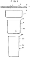
- Fig. 1 which schematically illustrates a step for producing a seamless can from a metal sheet coated with an organic film
- the coated metal sheet 10 is subjected to the draw working which has been known per se. to form a pre-draw-formed cup 13 which is then subjected to the known thickness-reducing redraw working which is disclosed, for example, in Japanese Laid-Open Patent Publication No. 258822/1989 to obtain a redraw-formed cup 5.
- the redraw-formed cup 5 has a bottom wall 5a and a side wall 5b, and further has a flange portion 5c formed at an upper end of the side wall 5b.
- a seamless can 20 is produced by using the pre-draw-formed cup 13 or the redraw-formed cup 5.
- a thick portion 20b is formed at the upper end (on the side of the opening portion) of a main portion 20a of the side wall and a flange 20c is formed further at an upper end portion thereof.
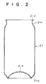
- the seamless can 20 produced according to the present invention is then subjected to the subsequent working and is formed into a container body 21 as shown in Fig. 2 and is put into practical use being filled with content and fitted with a closure.
- a foot portion 21a and a domed portion 21b are formed at the bottom of the container body 21.
- the flange 20c is trimmed, and a necked portion 21c having a reduced diameter is formed on the lower side of the flange 21d at the upper end portion due to the necking and flanging.
- the coated metal sheet (blank) 10 which is a basic constituent material of the seamless can 20 has an organic film 12 formed on both surfaces of a metal sheet 11 for cans.
- Examples of the metal sheet 11 for cans include a tin-free steel plate, a tin-plated steel plate, an electrically zinc-plated steel plate, a nickel-plated steel plate, an aluminum (alloy) thin plate and the like plate having a thickness of from 0.1 to 0.5 mm, which will be used depending upon the applications and sizes of cans.
- an undrawn film or biaxialy film of a thermoplastic resin for example, an olefin resin such as of polyethylene, polypropylene, ethylene-propylene copolymer, ethylene/vinyl acetate copolymer, ethylene/acryl ester copolymer, or ionomer, a polyester such as of polybutylene terephthalate, a polyamide such as nylon 6, nylon 6,6, nylon 11, or nylon 12, or polyvinyl chloride, polyvinylidene chloride, etc.
- a thermoplastic resin for example, an olefin resin such as of polyethylene, polypropylene, ethylene-propylene copolymer, ethylene/vinyl acetate copolymer, ethylene/acryl ester copolymer, or ionomer, a polyester such as of polybutylene terephthalate, a polyamide such as nylon 6, nylon 6,6, nylon 11, or nylon 12, or polyvinyl chloride, polyvinylidene chloride, etc.
- the organic film 12 may comprise a single layer of one of these films or a plurality of layers of such films.
- its thickness is usually from 3 to 50 ⁇ m.
- an adhesive agent such as urethane adhesive agent, epoxy adhesive agent, acid-modified olefin resin adhesive agent, copolyamide adhesive agent or copolyester adhesive agent.
- the thickness of the adhesive agent layer is usually from about 0.1 to 5.0 ⁇ m.
- the organic film 12 can be further formed by coating the metal sheet 11 for cans with at least one of a variety of thermoplastic paints or thermosetting paints followed by drying.
- Suitable examples of the paint include modified epoxy paints such as phenol epoxy and amino epoxy; vinyl chloride/vinyl acetate copolymer paint; saponified vinyl chloride/vinyl acetate copolymer paint; vinyl chloride/vinyl acetate/maleic anhydride copolymer paint; modified vinyl paints modified with epoxy, epoxyamino or epoxyphenol; acryl paint; synthetic rubber paints such as styrene/butadiene copolymer paint, and the like.
- the organic film 12 formed of these paints has a thickness of usually from about 2 to about 30 ⁇ m (dry thickness of film).
- the seamless can 20 is produced by using, for example, the aforementioned redraw-formed cup 5 or the pre-draw-formed cup 13.
- a variety of lubricating agents are those which arouse no problem from the standpoint of food sanitation and can be easily volatilized and removed upon heating at about 200 °C , such as liquid paraffin, synthetic paraffin, white vaseline, edible oil, hydrogenated edible oil, palm oil, a variety of natural waxes, polyethylene wax, etc.
- the amount of application should desirably be from 0.1 to 10 mg/dm2 Fig.
- FIG. 3 illustrates a step for effecting the thickness-reducing bend-elongation and the ironing working through one stroke according to the present invention
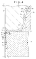
- Fig. 4 illustrates a major portion thereof on an enlarged scale
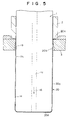
- Fig. 5 illustrates a state of when the forming is finished.
- Figs. 3 to 5 use is made of a punch 1, a blank holder 2 and an annular die 3 as principal tools for forming.
- the punch 1 is held by a punch plate (not shown), and the blank holder 2 is provided in the upper die shoe (not shown) in concentric with the punch 1 to surround the punch 1 maintaining a small gap 8 (see Fig. 4).
- the punch 1 and the blank holder 2 are so provided as to move up and down at a predetermined timing relying upon a mechanism such as crank mechanism (not shown) or the like.
- the annular die 3 is disposed in concentric with the punch 1, and is provided in the lower die shoe (not shown) via a die holder 4.
- annular bending member 6 On the flat surface portion 3a of the annular die 3 is secured an annular bending member 6 in concentric with the punch 1.
- the annular bending portion 6 forms a diameter-contracted portion at a lower portion of the side wall 5b of the cup 5 relying upon the continuous bend working, so that the side wall 5b can be smoothly introduced into the forming region and that the bend-elongation is effectively carried out.
- the punch 1 comprises a front portion 1a and a small-diameter portion 1b that is continuous to the front portion 1a via a tapered portion 1b1. That is, the front portion 1a is to form a main portion 20a of the seamless can 20 shown in Fig. 1, and the small-diameter portion 1b is to form a thick portion 20b of the seamless can 20.
- the blank holder 2 has a cylindrical outer peripheral surface 2f having an outer diameter which nearly corresponds to the inner diameter of the redraw-formed cup 5, and has a flat holding surface 2a formed at the lower portion thereof.
- a curved portion 2b to the end portion on the outer side of the holding surface 2a are continuing a curved portion 2b, a short cylindrical portion 2c and a titled portion 2d that upwardly extends toward the outer side in a tilted manner in the order mentioned.
- the tilted portion 2d is continuous to the outer peripheral surface 2f via a curved portion 2e (Fig. 3).
- the short cylindrical portion 2c and the tilted portion 2d together are forming a recessed portion 2g having a step.
- the lower portion of the blank holder 2 has a diameter smaller than that of the outer peripheral surface 2f such that the blank holder 2 can be inserted in the redraw-formed cup 5 to be formed.
- the annular bending member 6 is so disposed as to surround the blank holder 2 that is introduced into the redraw-formed cup 5, a portion 6a corresponding to the recessed portion 2g is curved, and a gap 9 between the curved portion 6a and the recessed portion 2g is set to be slightly larger than the thickness (t1) of the side wall 5b of the cup 5 to be formed.
- the annular die 3 has the flat and horizontal surface portion 3a and an annular working surface 50 (Fig. 3). These surfaces are continuous via a working corner 3b having a small radius of curvature Rd, and the annular working surface 50 is forming a cavity 7 which permits the punch 1 to be inserted or removed.
- On the annular working surface 50 is further formed an ironing portion 3b1 at a position which is the lower end of the working corner 3b.
- an escape surface 3e having a taper angle ⁇ with respect to the axial line, and a peripheral surface 3f of a conical truncated shape is formed continuous to the escape surface 3e.
- the ironing portion 3b1 is to execute the ironing working in cooperation with the punch 1 and inevitably protrudes most in the annular working surface 50.
- the redraw-formed cup 5 is formed as described below.
- the cup 5 coated with the lubricating agent is held on the annular die 4 or on the curved portion 6a of the annular bending member 6.
- the blank holder 2 is inserted in the cup 5, and the punch 1 is advanced into the cavity 7 of the annular die 3 (Fig. 3).
- the side wall 5b of the cup 5 is subjected to the bending repetitively such as inward bending along the curved portion 2e, reverse bending along the curved portion 6a and inward bending along the curved portion 2b in the order mentioned due to the blank holder and the annular bending member 6.
- the side wall 5b is pulled by the punch 1 and passes through the working corner 3b and the ironing portion 3b1 while being continuously subjected to the above-mentioned bend working and being pushed by the blank holder 2 onto the flat surface portion 3a of the annular die 3 to such a degree that wrinkles do not develop.
- the side wall 5b While passing through the working corner 3b, the side wall 5b is subjected to the above-mentioned repetitive bending and to a relatively large reverse tensile force due to the blank-holding force, and is further subjected to large bending and bend-elongation due to tension, and then passes through a gap 15 of a width of t3 defined by the ironing portion 3b1 and the punch 1 so as to be subjected to the ironing working.
- the side wall is subjected to the draw working until the inner surface thereof comes into contact with the punch 1 so that the thickness reduces from t1 to t2 and, after brought into contact with the punch 1 at a contact portion 5x, the side wall is subjected to the ironing working so that the thickness further reduces to t3 at the ironing portion 3b1.
- Thickness-reducing drawing ratio t1 - t2 t1 x 100
- the gap t3 between the ironing portion 3b1 and the punch 1 corresponds to the thickness of the side wall of the seamless can 20 that is to be formed.
- a gap relative to the portion 1a of the punch defines the thickness of the main portion 20a and a gap relative to the portion 1b of the punch defines the thickness of the thick portion 20b. That is, the punch 1 further advances from the state shown in Fig. 3, the flange portion 20c corresponding to the flange portion 5c of the cup 5 comes onto the flat surface portion 3a of the annular die 3 as shown in Fig. 5 to complete the forming; i.e., the seamless can 20 is formed having the main portion 20a of which the thickness is greatly reduced and having the thick portion 20b of a relatively large thickness at the upper portion.
- the portion (thick portion 20b) of the seamless can subjected to the necking is ironed by at least 5% and, particularly, by from 10 to 40%.
- the ironing ratio at this portion is smaller than 5%, the thickness does not become uniform in this portion and the organic film 12 is deteriorated as represented by whitening or the like.
- the punch 1 in the state of Fig. 5 is removed as described below.
- the die 3 is lowered from the bottom portion 20d of the seamless can 20 with the blank holder 2 being secured and, at the same time, the punch 1 is raised while blowing the air 16 through the air-guide hole lc formed in the punch 1.
- the flange portion 20c of the seamless can 20 is held by the blank holder 2 and stays at a position shown, permitting the punch 1 to be removed from the seamless can 20.
- the degree of thickness reduction by bend-elongation increases with a decrease in the radius of curvature Rd of the working corner 3b of the die 3.
- the radius of curvature Rd is so set that its ratio relative to the thickness tO of the coated metal sheet 10 (see Fig. 1), i.e., Rd/t0 lies within a range of from 1 to 2.9.
- Rd/t0 lies within a range of from 1 to 2.9.
- the ironing portion 3b1 is formed at the lower end of the working corner 3b, and the ironing working is executed immediately after the bend-elongation.
- the ironing portion 3b1 may be a circumferential line forming the end portion of the working corner 3b or may have a width in the axial direction from the circumferential line as viewed on the side sectional view of Fig. 4. Usually, this width should not be larger than 5 mm. In such an embodiment, the width of contact is short between the die 3 and the punch 1 during the ironing, and the punch 1 can be easily removed.
- the escape surface 3e is formed continuously to the ironing portion 3b1. With the escape surface 3e being formed, the seamless can 20 that has been formed can be easily removed from the die 3. It is desired that the escape angle ⁇ of the escape surface 3e relative to the axial line of the dies 3 is usually smaller than 5 degrees. When the escape angle ⁇ exceeds 5 degrees, the organic film 12 formed on the surface of the seamless can 20 tends to be scraped off when the seamless can 20 is removed.
- Fig. 4 illustrates the escape angle ⁇ presuming that the outer surface of the wall portion 5b after the ironing working is in parallel with the axial line.
- the surface temperature Td of portions of the die 3 that come into contact with the side wall 5b i.e., the surface temperature Td of the flat surface portion 3a and of the working corner 3b during the forming, is not higher than a glass transition temperature of the organic film 12 Tg + 50 °C but is not lower than 10 °C and, preferably, is not higher than Tg + 30 °C but is not lower than 15 °C .
- Tg + 50 °C the organic film 12 exhibits an increased coefficient of sliding friction and is softened. Therefore, during the forming and, particularly, during the ironing working, the organic film 12 on the outer surface is scraped off making it difficult to obtain satisfactory products.
- the barrel tends to be broken probably because of an increased sliding frictional resistance between the die 3 and, particularly, the flat surface portion 3a and the organic film 12 on the outer surface.
- the surface temperature Ts on the holding surface 2a of the bank holder 2 is not higher than the glass transition temperature of the organic film 12 Tg + 50 °C but is not lower than 20 °C and, preferably, is not higher than Tg + 30 °C but is not lower than 15 °C.
- the surface temperature Tp of the punch just after it is removed is not higher than the glass transition temperature of the organic film 12 Tg + 50 °C but not lower than 10 °C and, preferably, is not higher than Tg + 30 °C but is not lower than 15 °C .
- the surface temperature is higher than Tg + 50 °C, the film exhibits an increased coefficient of sliding friction and is softened.
- the punch 1 is removed from the seamless can 20, therefore, the organic film 12 on the inner surface is scraped off making it difficult to obtain satisfactory products.
- the surface temperature is lower than 10 °C , on the other hand, the punch 1 is removed with difficulty because of an increased coefficient of sliding friction between the surface of the punch 1 and the organic film 12.
- the seamless cans 20 are continuously produced by using a transfer press.
- the following method is preferably employed in order that the surface temperatures Td, Ts and Tp of the die 3, blank holder 2 and punch 1 lie within the above-mentioned temperature range.
- the hot water (preferably maintained at about 40 to 85 °C ) is permitted to flow through the die 3 prior to starting the forming operation, the hot water is changed over to the cold water (about 5 to 30 °C , more preferably, about 12 to 18 °C ) just before starting the forming operation and the cold water is permitted to flow continuously during the forming operation. That is, prior to starting the forming operation, the hot water is supplied to heat the die 3, blank holder 2 and punch 1 so as to have surface temperatures Td, Ts and Tp which are not lower than 10 °C . After the forming is started, the surface temperatures Td, Ts and Tp rise due to the heat of working and the heat of friction. In order to suppress the temperature rise and to maintain the surface temperatures Td, Ts and Tp not higher than Tg + 50 °C , the cold water is permitted to flow through the die 3, blank holder 2 and punch 1.
- the method of effecting the bend-elongation and ironing working through one stroke is very advantageous in economy as it improves breaking limit owing to the mutual action of working forces acting in different directions, simplifies the steps and reduces the cost of tools.
- the production method shown in Figs. 3 to 5 has dealt with the case of producing seamless cans 20 having a side wall (barrel portion) of which the upper portion is made thick as shown in Fig. 1.
- This method can also be adapted to producing seamless cans 20' as shown in Fig. 6.
- the central portion 20'a1 of the barrel 20'a is made thick over about one-third of the height.
- the seamless can 20' can be produced through the operation quite in the same manner as the method shown in Figs. 3 to 5 except that a portion corresponding to the thick portion 20'a1 is rendered to have a small diameter.
- the seamless can 20' of this type has a relatively large dent strength in the barrel portion 20'a and is adapted to the so-called negative-pressure canning in which the pressure becomes negative. Even in this case, the portion (portion higher than 20'a1) subjected to the necking is ironed at an ironing ratio of not smaller than 5% and, particularly, from 10 to 40%. So far as such an ironing working is carried out, the ironing ratio in the thick portion 20'a1 may be very smaller than the above-mentioned range.
- Figs. 7 to 11 illustrate other embodiments for effecting the bend-elongation (thickness-reducing redraw working) and the ironing working in one stroke.
- the radius of curvature at the working corner 3b of the die 3, ironing ratio and controlling the temperatures of the working tools are the same as those of the method shown in Figs. 3 to 5, but the position of the ironing portion 3b1 is changed.
- the ironing portion 3g formed in the annular working surface of the die 3 has a suitable width in the axial direction and is continuous to the working corner 3b via the approach surface 3c. That is, as the punch 1 advances, the side wall 5b is bend-elongated by the working corner 3b of the die 3 while receiving a relatively large reverse tension and bending force of a large curvature, so that the thickness is reduced from t1 to t2.
- the side wall 5b then advances in the cavity being slightly tilted inwardly along the approach surface 3c, passes through a gap 15 between the ironing portion 3g and the punch 1 owing to the cooperation of the punch 1, ironing portion 3g and approach surface 3c so as to be ironing worked, whereby the thickness is further reduced from t2 to t3. That is, the side wall 5b comes into contact with the punch 1 before arriving at the ironing portion 3g as shown.
- the heat generated by bend-elongation at the working corner 3b escapes into the die 3 via the approach surface 3c giving an advantage that the temperature rise of the material 5b to be worked is suppressed.
- the wall 5b of the cup 5 that is to be worked is outwardly pulled in a tilted manner along the approach surface 3c and is ironed by the punch 1 at the ironing portion 3g.
- an approach angle ⁇ subtended by the approach surface 3c relative to the axis of the die 3 is within a range of from 1 to 5 degrees
- the junction portion 3d between the ironing portion 3g and the approach surface 3c is a sharp corner portion or a curvature portion having a radius of curvature Ri which is smaller than 0.3 x t0 (t0 is the thickness of the blank 10).
- the approach angle ⁇ is not larger than 5 degrees, the load exerted on the junction portion 3d due to the ironing can be decreased, and the organic film 12 on the outer surface can be effectively prevented from being scraped off during the ironing.
- the approach angle ⁇ is smaller than 1 degree, on the other hand, the ironing surface pressure (force for outwardly pushing the entire die 3) becomes so large that the annular working surface of the die 3 undergoes an elastic deformation in a manner to outwardly expand in the radial direction. Therefore, the gap increases between the punch 1 and the ironing portion 3g, making it difficult to obtain a predetermined ironing ratio.
- the gap (between the punch 1 and the ironing portion 3g) returns to the initial narrow gap due to the elastic recovery of the die 3. Accordingly, the punch 1 is tightened and is removed with difficulty.
- the approach angle ⁇ can be set to be relatively large such as from 1 to 45 degrees. That is, when Ri is set to be relatively large, stress concentrating at the ironing portion 3g becomes relatively small.
- the approach angle ⁇ within a range of from 1 to 45 degrees, the organic film 12 on the outer surface is not scraped off during the ironing, a desired ironing ratio is obtained and the punch 1 can be easily removed.
- the ironing load becomes too great that the wall 5b of the material being worked is broken and the organic film 12 on the outer surface is easily scraped off.
- the radius of curvature Ri is larger than 20 x t0 despite the approach angle ⁇ is smaller than 45 degrees, the ironing portion 3g undergoes elastic deformation due to the ironing surface pressure, and it becomes difficult to obtain a desired ironing ratio and the punch 1 is removed with difficulty because of the same reasons as described above.
- the die 3 is constituted by a die 3x for bend working and a die 3y for ironing working, the two dies being secured to each other. That is, the die is substantially the same as that of the embodiment of Fig. 7 except that the annular working surface below the working corner 3b of the bending die 3x is tilted downwardly and is forming an annular recessed portion 14 in the way to the ironing portion 3g.
- a portion between the lower end 3b1 of the working corner 3b and the junction portion 3d of the ironing die 3y works as the approach surface having the approach angle ⁇ , and the wall 5b of the material to be worked is not in contact with the die 3 without, however, arousing any problem.
- This embodiment is advantageous from the standpoint that the forming tools can be easily manufactured and maintained.
- the approach surface 3c of the die 3 shown in Fig. 7 is a surface of curvature having a radius of curvature Rc which slightly protrudes toward the punch 1.
- the approach angle ⁇ in this case is determined based upon a straight line connecting the lower end 3b1 of the working corner 3b to the junction portion 3d (upper end 3d1 when the junction portion 3d is a curvature portion).
- the ironing portion 3g is formed in the junction portion 3d only at the lower end of the approach surface 3c of the die 3 of Fig. 7, and an escape surface 3e having an escape angle ⁇ of smaller than 5 degrees is formed in the ironing portion 3g. That is, the ironing portion 3g describes a circumferential line formed by the junction portion 3d.
- the junction portion 3d (ironing portion 3g) may be a sharp corner or a curvature portion, as a matter of course.
- the approach surface 3c of the die 3 in Fig. 7 is constituted by an approach surface (rear approach surface) 3c1 on the side of the working corner and an approach surface (front approach surface) 3c2 on the side of the ironing portion.
- the approach angle ⁇ of the rear approach surface 3c1 is within a range of from 1 to 15 degrees and the approach angle ⁇ of the front approach surface 3c2 is smaller than ⁇ and lies within a range of from 1 to 5 degrees.
- a junction portion 3d1 between the two approach surfaces and a junction portion 3d2 between the front approach surface 3c2 and the ironing portion 3g are sharp corners or curvature portions having a radius of curvature Ri of not larger than 0.3 x t0.
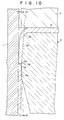
- the ironing portion 3g is formed under the junction portion 3d2 maintaining a predetermined width, it is also allowable that the ironing portion 3g is the junction portion 3d itself or the circumferential line as shown in Fig. 10.
- the escape surface may be constituted being continuous to the ironing portion 3g like in the aforementioned various embodiments.
- Figs. 12 and 13 illustrate an embodiment in which the bend-elongation and the ironing working are carried out in separate steps, i.e., in two strokes.
- a thickness-reduced redraw-formed cup 37 (Fig. 13) having a thickness of the side wall that is reduced from t1 to t2 is formed by using a redrawing tool 30 that is equipped with a punch 31, a blank holder 32, a redrawing die 33 having a working corner 33b and an escape surface 33e with a small radius of curvature Rd, and an annular bending member 36 of nearly the same structure as that of the apparatus shown in Figs. 3 and 7 but having neither the approach surface 3c nor the ironing portion 3g, under the same redrawing conditions (same die surface temperature Td, etc.), and by advancing the punch 31 to redraw-form the draw-formed metal cup 5.
- a redrawing tool 30 that is equipped with a punch 31, a blank holder 32, a redrawing die 33 having a working corner 33b and an escape surface 33e with a small radius of curvature Rd, and an annular bending member 36 of nearly the same structure as
- a seamless can 20 is produced by ironing the thickness-reduced redraw-formed cup 37 by using a punch 34 and an ironing die 35 having an approach surface 35c with an approach angle ⁇ , a junction portion 35d with a radius of curvature Ri and an ironing portion 35g under the same ironing conditions (die surface temperature, etc.) as those of the case of one-stroke forming method.
- the portion to be subjected to the necking is ironed at an ironing ratio of at least 5% and, particularly, from 10 to 40%.
- the ironing portion may be the one of the type shown in Figs. 10 and 11.
- the approach angle ⁇ of the approach surface 35c is from 1 to 30 degrees, and the junction portion 35d between the approach surface 35c and the ironing portion 35g has a radius of curvature Ri that lies within a range of (0.3 to 20) x t0.
- the upper limit of the approach angle ⁇ is different from that of the case of the one-stroke forming method because of the reason that in the case of the two-stroke forming method, the force of the axial direction produced at the working corner of the die 35 does not act upon the ironing portion 35g.
- the above-mentioned two-stroke forming method is advantageous in regard to that the machining tools can be easily manufactured and maintained while suppressing the heat generated in the material due to the working.
- Both the above-mentioned one-stroke forming method and two-stroke forming method have dealt with the cases of using a stepped punch.
- the ironing ratio lies within the above-mentioned range in the portion that is to be subjected to the necking, however, it is allowable to execute the forming by using a straight punch without stepped portion. In this case, the inner surface of the side wall of the seamless can becomes straight.
- the ironing working is further executed in one stroke after the above-mentioned bend-elongation (thickness-reducing redraw working) and ironing working, making it possible to produce a seamless can 20'' having an opening end 20''b that outwardly protrudes beyond the main barrel portion 20'' a and is thickened as shown in Fig. 16.
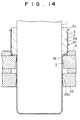
- the seamless can may be formed in one stroke by the method shown in Figs. 14 and 15.
- Fig. 14 illustrates a state where the draw-formed metal cup 5 is being formed by using an ironing die 23 disposed near the front of the die 3 and a thickness-reducing redrawing/ironing tool 22 having the same blank holder 2, die 3 and annular bending member 6 as those shown in Fig. 3 which are controlled at the same temperatures as those of Fig. 3, except that a punch 1' has a uniform diameter over the whole length of the working portion (corresponds to the front portion la and to the diameter-contracted portion 1b of the punch 1 of Fig.
- the punch 1' has a working portion of a cylindrical shape making a difference from the punch 1, the surface temperature Td of the ironing die 23 being controlled like that of the thickness-reducing redrawing/ironing tool 22.
- the distance between the flat surface portion 3a of the die 3 and the ironing portion 23a or the upper end thereof of the die 23 is equal to the length between the upper end 20''b1 of thick portion of the opening end 20''b and the lower end of the tilted portion 20''b2.
- the thickness-reducing redrawing/ironing is executed by advancing the punch 1' of the tool 22 until the thickness of the side wall 5b of the draw-formed cup 5 is reduced by the die 3 to a predetermined value (thickness of the open end portion 20''b), and the ironing is executed by the die 23 until the flange portion 20''c (corresponds to the flange portion 5c) reaches the flat surface portion 3a of the die 3, so that the main barrel portion 20''a having a predetermined thickness is obtained.
- the die 3 may be the one other than Fig. 3, e.g., may be those shown in Figs. 7 to 11. Moreover, the ironing portion of the die 23 may be as shown in Fig. 13 to which only, however, the invention is in no way limited.
- the thickness (tw) of wall of can barrel is selected to be as small as possible to reduce the weight of the container, and the thickness (tf) of wall of necking portion (upper side of barrel portion) is so selected that the necking can be easily effected, i.e., tf > tw.
- a stepped portion is formed in the inner surface of the side wall to adjust the thickness.
- This method is called internal step method.
- an annular die 3 having a large ironing diameter is arranged on the upper side and an annular die 23 having a small ironing diameter is arranged on the lower side, the thickness is adjusted by forming a step on the outer surface of the side wall. This method is called external step method.
- the internal step method is very advantageous from the standpoint of preventing breakage in the drum (breakage in the wall portion) just before the can-forming working is finished, since the upper part (necking part) of the can barrel which is subjected to severe working condition is formed at a low ironing ratio.
- the ironing working is effected at one time such that the wall thickness is reduced from t2 to tw (which is smaller than tf), arousing a problem that the organic film 12 is scraped off during this stage.
- the inner diameter of the can that is formed becomes small toward the upper side, there remains inconvenience in regard to removing the punch 1.
- the ironing working for forming the can barrel under the necking portion is stepwisely effected, i.e., t2 ⁇ tf ⁇ tw, giving advantage in that the organic film 12 is prevented from being scraped off. Moreover, there remains no problem in regard to removing the punch 1. However, since a step is formed on the outer surface of the can barrel, the appearance is not satisfactory. Even in ironing the upper part of the can barrel which is subjected to severe working condition to obtain the wall thickness tf, the ironing has been executed for the lower side to accomplish the smallest thickness tw, arousing a problem in that the barrel tends to be broken at the external step portion.
- Figs. 18 and 19 illustrate an embodiment of this method (hereinafter referred to as internal/external step method). That is, referring to Fig. 18 illustrating a can-forming step based on the internal/external step method, the punch 1 has a front portion (lower portion 1a) with a diameter corresponding to the inner diameter of the main barrel portion of the seamless can and a small diameter portion 1b corresponding to the inner diameter of a portion that will be subjected to the necking, like the one shown in Fig. 3, a tapered portion 1b1 being formed therebetween. Like the one shown in Fig.
- the annular die has an upper annular die 3 and a lower annular die 23, the diameter of the ironing portion 3g formed in the working surface of the upper annular die 3 being larger than the diameter of the ironing portion 23a of the lower annular die 23. That is, the diameter of the ironing portion 3g corresponds to the outer diameter of the portion of the seamless can that will be subjected to the necking, and the diameter of the ironing portion 23a corresponds to the outer diameter of the main barrel portion.
- a seamless can 60 shown in Fig. 19 is obtained by advancing the punch 1 and executing the can- forming working like in the embodiment of Fig. 14.
- the seamless can 60 has a main barrel portion 60a of a reduced thickness tw and a portion (thick portion) 60b of a thickness tf that will be subjected to the necking, forming steps on both the inner surface and the outer surface from the main barrel portion 60a to the thick portion 60b.
- the annular dies 3 and 23 are in no way limited to those shown in Fig. 18 but may be those having shapes shown in other drawings.
- the main barrel portion 60a is ironed in two steps through the ironing portion 3g of the upper annular die 3 and the ironing portion 23a of the lower annular die 23, the thick portion 60b being ironed in one step by the ironing portion 3g at an ironing ratio of at least 5% and, preferably, from 10 to 40%.
- This ironing working is quite the same as the aforementioned ironing working of the embodiment of Figs. 14 and 15.
- balance and the like between the step formed on the inner surface and the step formed on the outer surface should be so set that the merits of the internal step method and of the external step method can be effectively utilized. Even in this method, the temperatures of the tools used for the forming are adjusted in the same manner as that of the one-stroke method that was described already.
- a paraffin wax (melting point MT: 60 °C ) was applied in an amount of about 50 mg/m2 onto both surfaces of a laminated steel plate (total thickness of 0.230 mm) that was obtained by heat-adhering a biaxially drawn ethylene terephthalate/ethylene isophthalate copolymer (molar ratio: 88/12, melting point: 230 °C , glass transition temperature Tg: 70 °C ) film 12 having a thickness of 0.020 mm onto both surfaces of a tin-free steel plate (electrolytic chromate-treated steel plate) having a thickness of 0.19 mm and a tempering degree of T-4 (Rockwell 30T hardness: 58 to 64).
- the laminated steel plate was punched by using a draw-forming machine (not shown) into a circular blank 10 having a diameter of 165 mm.
- a draw-forming machine not shown
- the blank 10 was then draw-worked at a drawing ratio of 1.65 to obtain a pre-draw-formed cup 13 (Fig. 1) having an average height of 45 mm and an inner diameter of 100 mm.
- the pre-draw-formed cup 13 was subjected to the thickness-reducing redraw-working relying upon bend-elongation only at a drawing ratio of 1.23 in order to obtain a redraw-formed cup 5 having a height of 72 mm, an inner diameter of 81.3 mm and an average thickness of the side wall portion of 0.2 mm (average thickness-reducing ratio: 13%).
- the redraw-formed cup 5 was subjected to the redraw-forming and ironing working (Test Nos. 1 to 9, 14 and 15) by setting the surface temperature Tp of the punch 1 immediately after removed at 60 °C but except for the Text Nos. 5 and 6 (the surface temperature Tp was 15 °C in the case of Text No. 5 and was 150 °C in the case of Test No. 6), and by changing the radius of curvature Rd of the working corner 3b of the die 3, approach angle ⁇ , gap width between the punch 1 and the ironing portion 3g, and surface temperature Td of the die 3.
- the die 3 In the cases of Test Nos. 1 to 6, 9, 12 and 13, the die 3 possessed Ri/t0 of 0.2. In the case of Test No. 7, the die 3 possessed Ri/t0 of 10. In the cases of Test Nos. 14 and 15, the dies 3 possessed approach angles 7 of the front approach surfaces 3c2 of 2 degrees and 8 degrees, respectively.
- the redraw-formed cup 5 was subjected to the thickness-reducing redraw-working by using the apparatus shown in Fig. 12 (Test Nos. 10, 11, Tp was 60 °C).
- the punch 1 possessed a diameter in the front portion la of 66 mm, and the drawing ratio was 1.24.
- a seamless can 20 was prepared based on the internal/external step method shown in Figs. 18 and 19.
- the punch 1 possessed a step of 0.01 mm, and a step between the two ironing portions was 0.009 mm.
- Table 1 shows the working conditions and Table 2 shows the results of working.
- Table 1 shows the "Drawing” and “Thickness-reducing ratio” are abbreviations of thickness- reduction increment.
- the thickness-reducing ratio in the draw working is -3% which means that the thickness of the side wall 5b is increased by 3%.
- “Appearance good” stands for a state where the organic film 12 on the outer surface is smoothed by the ironing working, offering excellent printability.
- Test Nos. 1 to 9 and 12 to 15 the step of the punch is tf - tw and in Test No. 16, the step of punch plus step of ironing portion corresponds to tf - tw.
- Table 2 Test No. Formability Damage in organic film on the outer surface Necking, flanging workability Appearance 1 normal normal good good 2 normal outer surface scraped off not evaluated not evaluated 3 broken not evaluated not evaluated not evaluated 4 broken not evaluated not evaluated not evaluated 5 poorly removed normal not evaluated not evaluated 6 normal inner surface scraped off not evalupated good 7 normal normal good good 8 normal normal good good 9 can hight insufficient outer surface scraped off organic film whitened poor 10 can hight insufficient normal organic film whitened poor 11 broken not evaluated not evaluated not evaluated 12 normal normal good good 13 normal outer surface scraped off not evaluated not evaluated 14 normal normal good good 15 normal outer surface scraped off not evaluated 16 normal normal normal good good
- Test No. 1 As shown in Tables 1 and 2, there were obtained a seamless can 20 and a container 21 having desired sizes of a height of 180 mm and an inner diameter of 66 mm, which were satisfactory.
- a curve of Test No. 1 of Fig. 17 represents a relationship between the thickness of the barrel portion of the seamless can 20 that was obtained and the height from the bottom of the can, from which it will be understood that the thickness is constant from a height of about 20 mm to a height of about 90 mm from the bottom of the can.
- the thickness slightly increases from a height of about 100 mm to a height of about 120 mm from the bottom of the can, since this portion corresponds to the diameter-contracted portion 1b of the punch 1, i.e., corresponds to the opening end portion 20b.
- the portion which is slightly thickened near the opening end portion is desirable since it does not develop cracking during the necking or flanging.
- the can could be formed but the punch 1 could not be removed from the seamless can 20, and the subsequent forming operations could not be carried out.
- Test No. 10 which was a conventional thickness-reducing redraw-forming method based only upon the redraw-forming but without effecting the ironing working
- Rd/t0 was just at the verge of the lower limit of claim 4 but the thickness of the side wall portion 5b could not be reduced to a sufficient degree, and a predetermined height of can was not obtained.
- the thickness of the sheet varied to a large degree in the direction of height.
- the organic film 12 at the necked portion was whitened, the appearance was poor, and a satisfactory seamless can 20 and a container 21 could not be obtained.
- a paraffin wax (melting point MT: 60 °C ) was applied in an amount of about 50 mg/m2 onto both surfaces of a laminated steel plate (total thickness of 0.230 mm) that was obtained by heat-adhering a biaxially drawn ethylene terephthalate/ethylene isophthalate copolymer (molar ratio: 88/12, melting point: 230 °C, glass transition temperature Tg: 70 °C ) film 12 having a thickness of 0.020 mm onto both surfaces of a tin-free steel plate (electrolytic chromate-treated steel plate) having a thickness of 0.19 mm and a tempering degree of T-4 (Rockwell 30T hardness: 58 to 64).
- the laminated steel plate was punched by using a draw-forming machine (not shown) into a circular blank 10 having a diameter of 165 mm.
- the blank 10 was then draw-worked at a drawing ratio of 1.70 to obtain a pre-draw-formed cup 13 having an average height of 46.5 mm, an inner diameter of 97 mm and an average thickness in the side wall portion of 0.250 mm (average thickness-reducing ratio, -8%).
- the punch 1 was the one that was used in Experimental Example 1.
- the thickness-reducing ratios through the drawing and ironing were 10% and 39%, and the final thickness-reducing ratio was 40%.
- the barrel was broken and the organic film 12 on the outer surface was scraped off, making it difficult to accomplish the forming.
Landscapes
- Engineering & Computer Science (AREA)
- Mechanical Engineering (AREA)
- Shaping Metal By Deep-Drawing, Or The Like (AREA)
- Containers Having Bodies Formed In One Piece (AREA)
Applications Claiming Priority (2)
| Application Number | Priority Date | Filing Date | Title |
|---|---|---|---|
| JP3935894 | 1994-02-15 | ||
| JP39358/94 | 1994-02-15 |
Publications (2)
| Publication Number | Publication Date |
|---|---|
| EP0667193A1 true EP0667193A1 (de) | 1995-08-16 |
| EP0667193B1 EP0667193B1 (de) | 1998-07-15 |
Family
ID=12550857
Family Applications (1)
| Application Number | Title | Priority Date | Filing Date |
|---|---|---|---|
| EP95300932A Expired - Lifetime EP0667193B1 (de) | 1994-02-15 | 1995-02-15 | Verfahren zur Herstellung falznahtloser Dosen |
Country Status (5)
| Country | Link |
|---|---|
| US (1) | US5778722A (de) |
| EP (1) | EP0667193B1 (de) |
| KR (1) | KR100254293B1 (de) |
| DE (1) | DE69503400T2 (de) |
| TW (1) | TW252961B (de) |
Cited By (15)
| Publication number | Priority date | Publication date | Assignee | Title |
|---|---|---|---|---|
| GB2323803B (en) * | 1997-04-04 | 2001-09-19 | British Steel Plc | A method of producing metal cans |
| WO2003037544A1 (fr) * | 2001-10-29 | 2003-05-08 | Daiwa Can Company | Dispositif et procede de fabrication d'une coque de recipient sans soudures en metal a revetement en resine |
| RU2211107C2 (ru) * | 1998-03-04 | 2003-08-27 | Корус Стал Б.В. | Способ получения консервных банок посредством утонения стенок |
| EP1294622B1 (de) * | 2000-06-16 | 2004-04-07 | Corus Staal BV | Druckfeste metallverpackung bestehend aus einer metalldose und verfahren zu ihrer herstellung |
| EP1136154B1 (de) * | 1999-09-30 | 2008-08-27 | Daiwa Can Company | Verfahren zur herstellung einer dose in flaschenform |
| WO2015181791A1 (en) * | 2014-05-30 | 2015-12-03 | Anheuser-Busch, Llc | Two iron tool pack and method for forming tall metal bottle shaped containers and such a metal bottle |
| RU2582828C2 (ru) * | 2012-09-25 | 2016-04-27 | Открытое акционерное общество "Производственное объединение "Завод имени Серго" | Способ изготовления полой тонкостенной конической детали с малым углом конусности и дном с малым радиусом |
| RU2582827C2 (ru) * | 2012-09-24 | 2016-04-27 | Открытое акционерное общество "Производственное объединение "Завод имени Серго" | Штамп для изготовления полой тонкостенной конической детали с малым углом конусности и дном с малым радиусом |
| US9527128B2 (en) | 2013-06-28 | 2016-12-27 | Nisshin Steel Co., Ltd. | Ironing mold and formed material manufacturing method |
| GB2547016A (en) * | 2016-02-04 | 2017-08-09 | Crown Packaging Technology Inc | Metal containers and methods of manufacture |
| US10022773B2 (en) | 2014-04-30 | 2018-07-17 | Alcoa Usa Corp. | Aluminum sheet with enhanced formability and an aluminum container made from aluminum sheet |
| US10239648B2 (en) | 2014-10-28 | 2019-03-26 | Ball Metalpack, Llc | Apparatus and method for forming a cup with a reformed bottom |
| US10315242B2 (en) | 2014-10-15 | 2019-06-11 | Ball Metalpack, Llc | Apparatus and method for simultaneously forming a contoured shoulder and neck portion in a closed end of a metallic container |
| EP3495059A1 (de) * | 2017-12-05 | 2019-06-12 | Tata Steel IJmuiden B.V. | Verfahren zur herstellung von dosenkörpern |
| EP3520919A4 (de) * | 2016-10-03 | 2019-12-04 | Nisshin Steel Co., Ltd. | Verfahren zur herstellung von formmaterial und formmaterial |
Families Citing this family (26)
| Publication number | Priority date | Publication date | Assignee | Title |
|---|---|---|---|---|
| GB2340420A (en) * | 1998-08-07 | 2000-02-23 | British Steel Plc | Aerosol container |
| US6205831B1 (en) * | 1998-10-08 | 2001-03-27 | Rayovac Corporation | Method for making a cathode can from metal strip |
| US20030198537A1 (en) * | 2002-04-22 | 2003-10-23 | Larsen Robert B. | Method for inhibiting delamination of a polymeric coating from a container body |
| US20040035871A1 (en) * | 2002-08-20 | 2004-02-26 | Thomas Chupak | Aluminum aerosol can and aluminum bottle and method of manufacture |
| JP4962698B2 (ja) * | 2003-12-17 | 2012-06-27 | 東洋製罐株式会社 | 合成樹脂被覆金属缶体の製造方法及び装置 |
| US8499462B2 (en) | 2006-04-10 | 2013-08-06 | The Gillette Company | Cutting members for shaving razors |
| US8011104B2 (en) | 2006-04-10 | 2011-09-06 | The Gillette Company | Cutting members for shaving razors |
| ES2344742T3 (es) * | 2006-07-26 | 2010-09-06 | Impress Group B.V. | Metodo y aparato para conformar un recipiente de acero a presion, dicho recipiente de acero a presion y una preforma del mismo. |
| US8245551B2 (en) | 2008-04-24 | 2012-08-21 | Crown Packaging Technology, Inc. | Adjustable transfer assembly for container manufacturing process |
| US7997111B2 (en) * | 2008-04-24 | 2011-08-16 | Crown, Packaging Technology, Inc. | Apparatus for rotating a container body |
| WO2010048727A1 (en) * | 2008-10-31 | 2010-05-06 | Novelis Inc. | Necking die with redraw surface and method of die necking |
| US20100126244A1 (en) * | 2008-11-27 | 2010-05-27 | Yong-Wah Chien | Method for forming high tensile strength metal sheet |
| CN102470485B (zh) | 2009-07-28 | 2014-12-31 | 新日铁住金株式会社 | 激光处理装置及容器制造装置 |
| RU2418646C1 (ru) * | 2009-10-12 | 2011-05-20 | Федеральное государственное унитарное предприятие "Муромский приборостроительный завод" (ФГУП "МПЗ") | Способ изготовления полых изделий |
| JP5573511B2 (ja) * | 2010-09-02 | 2014-08-20 | トヨタ紡織株式会社 | 成形体の製造方法 |
| JP2013082109A (ja) * | 2011-10-07 | 2013-05-09 | Toyo Seikan Kaisha Ltd | しわ発生の少ない紙成形体とその製造方法 |
| DE102012203277A1 (de) * | 2012-03-01 | 2013-09-05 | Mall + Herlan Gmbh | Selbstentleerende Verpackung und Vorrichtung und Verfahren zu ihrer Herstellung |
| JP6066896B2 (ja) | 2013-12-17 | 2017-01-25 | 日新製鋼株式会社 | 成形材製造方法 |
| JP6352065B2 (ja) * | 2014-06-13 | 2018-07-04 | 日新製鋼株式会社 | 成形材製造方法 |
| US20180229287A1 (en) * | 2015-08-26 | 2018-08-16 | Toyo Seikan Group Holdings, Ltd. | Die for ironing working and die module |
| US10850584B2 (en) * | 2016-06-07 | 2020-12-01 | Beijingwest Industries Co., Ltd. | Damper housing and a method for manufacturing the damper housing |
| USD827685S1 (en) * | 2016-12-19 | 2018-09-04 | Stolle Machinery Company, Llc | Truncated dome cup |
| USD839935S1 (en) * | 2016-12-19 | 2019-02-05 | Stolle Machinery Company, Llc | Truncated dome cup |
| RS63606B1 (sr) | 2017-12-05 | 2022-10-31 | Tata Steel Ijmuiden Bv | Postupak proizvodnje tela limenki |
| MX2020011180A (es) * | 2018-04-30 | 2020-11-12 | Westrock Mwv Llc | Recipiente de carton recubierto, metodo de manufactura de un recipiente de carton recubierto y aparato formador de fondo de vaso. |
| JP2022057514A (ja) * | 2020-09-30 | 2022-04-11 | 東洋製罐株式会社 | 容器の製造方法および容器の製造装置 |
Citations (5)
| Publication number | Priority date | Publication date | Assignee | Title |
|---|---|---|---|---|
| WO1981001259A1 (en) * | 1979-10-31 | 1981-05-14 | Metal Box Co Ltd | A method and tool for redrawing |
| GB2092985A (en) * | 1981-02-13 | 1982-08-25 | American Can Co | Drawn-and-ironed metal |
| US4346580A (en) * | 1980-08-26 | 1982-08-31 | National Steel Corporation | Manufacture of lightweight drawn and ironed can bodies |
| US4711611A (en) * | 1986-07-23 | 1987-12-08 | Dayton Reliable Tool & Mfg. Co. | Method and apparatus for fabricating a can body |
| GB2240503A (en) * | 1989-10-18 | 1991-08-07 | Toyo Seikan Kaisha Ltd | Draw-formed can |
Family Cites Families (3)
| Publication number | Priority date | Publication date | Assignee | Title |
|---|---|---|---|---|
| US4522049A (en) * | 1983-03-14 | 1985-06-11 | Aluminum Company Of America | Aluminum alloy food can body and method for making same |
| GB8913209D0 (en) * | 1989-06-08 | 1989-07-26 | Metal Box Plc | Method and apparatus for forming wall ironed articles |
| DE69417001T2 (de) * | 1993-12-22 | 1999-11-11 | Toyo Kohan Co., Ltd. | Verfahren zum Formen eines metallischen Behalters |
-
1995
- 1995-02-14 TW TW084101318A patent/TW252961B/zh active
- 1995-02-15 DE DE69503400T patent/DE69503400T2/de not_active Expired - Fee Related
- 1995-02-15 EP EP95300932A patent/EP0667193B1/de not_active Expired - Lifetime
- 1995-02-15 KR KR1019950002794A patent/KR100254293B1/ko not_active Expired - Fee Related
-
1997
- 1997-06-09 US US08/871,769 patent/US5778722A/en not_active Expired - Fee Related
Patent Citations (5)
| Publication number | Priority date | Publication date | Assignee | Title |
|---|---|---|---|---|
| WO1981001259A1 (en) * | 1979-10-31 | 1981-05-14 | Metal Box Co Ltd | A method and tool for redrawing |
| US4346580A (en) * | 1980-08-26 | 1982-08-31 | National Steel Corporation | Manufacture of lightweight drawn and ironed can bodies |
| GB2092985A (en) * | 1981-02-13 | 1982-08-25 | American Can Co | Drawn-and-ironed metal |
| US4711611A (en) * | 1986-07-23 | 1987-12-08 | Dayton Reliable Tool & Mfg. Co. | Method and apparatus for fabricating a can body |
| GB2240503A (en) * | 1989-10-18 | 1991-08-07 | Toyo Seikan Kaisha Ltd | Draw-formed can |
Cited By (23)
| Publication number | Priority date | Publication date | Assignee | Title |
|---|---|---|---|---|
| GB2323803B (en) * | 1997-04-04 | 2001-09-19 | British Steel Plc | A method of producing metal cans |
| RU2211107C2 (ru) * | 1998-03-04 | 2003-08-27 | Корус Стал Б.В. | Способ получения консервных банок посредством утонения стенок |
| EP1136154B1 (de) * | 1999-09-30 | 2008-08-27 | Daiwa Can Company | Verfahren zur herstellung einer dose in flaschenform |
| EP1294622B1 (de) * | 2000-06-16 | 2004-04-07 | Corus Staal BV | Druckfeste metallverpackung bestehend aus einer metalldose und verfahren zu ihrer herstellung |
| WO2003037544A1 (fr) * | 2001-10-29 | 2003-05-08 | Daiwa Can Company | Dispositif et procede de fabrication d'une coque de recipient sans soudures en metal a revetement en resine |
| US7191632B2 (en) | 2001-10-29 | 2007-03-20 | Daiwa Can Company | Device and method for manufacturing resin coated metal seamless container shell |
| RU2582827C2 (ru) * | 2012-09-24 | 2016-04-27 | Открытое акционерное общество "Производственное объединение "Завод имени Серго" | Штамп для изготовления полой тонкостенной конической детали с малым углом конусности и дном с малым радиусом |
| RU2582828C2 (ru) * | 2012-09-25 | 2016-04-27 | Открытое акционерное общество "Производственное объединение "Завод имени Серго" | Способ изготовления полой тонкостенной конической детали с малым углом конусности и дном с малым радиусом |
| US9527128B2 (en) | 2013-06-28 | 2016-12-27 | Nisshin Steel Co., Ltd. | Ironing mold and formed material manufacturing method |
| US10022773B2 (en) | 2014-04-30 | 2018-07-17 | Alcoa Usa Corp. | Aluminum sheet with enhanced formability and an aluminum container made from aluminum sheet |
| CN106457342A (zh) * | 2014-05-30 | 2017-02-22 | 安海斯-布希有限公司 | 用来形成高金属瓶形容器的二变薄工具包和方法 |
| WO2015181791A1 (en) * | 2014-05-30 | 2015-12-03 | Anheuser-Busch, Llc | Two iron tool pack and method for forming tall metal bottle shaped containers and such a metal bottle |
| CN106457342B (zh) * | 2014-05-30 | 2019-12-13 | 安海斯-布希有限公司 | 形成金属瓶形容器的方法 |
| AU2015265443B2 (en) * | 2014-05-30 | 2020-01-30 | Anheuser-Busch, Llc | Two iron tool pack for forming tall metal bottle-shaped containers |
| US10315242B2 (en) | 2014-10-15 | 2019-06-11 | Ball Metalpack, Llc | Apparatus and method for simultaneously forming a contoured shoulder and neck portion in a closed end of a metallic container |
| US10239648B2 (en) | 2014-10-28 | 2019-03-26 | Ball Metalpack, Llc | Apparatus and method for forming a cup with a reformed bottom |
| GB2547016A (en) * | 2016-02-04 | 2017-08-09 | Crown Packaging Technology Inc | Metal containers and methods of manufacture |
| WO2017134413A1 (en) * | 2016-02-04 | 2017-08-10 | Crown Packaging Technology, Inc. | Metal containers and methods of manufacture |
| GB2547016B (en) * | 2016-02-04 | 2019-04-24 | Crown Packaging Technology Inc | Metal containers and methods of manufacture |
| US11059086B2 (en) | 2016-02-04 | 2021-07-13 | Crown Packaging Technology, Inc. | Metal containers and methods of manufacture |
| US11883872B2 (en) | 2016-02-04 | 2024-01-30 | Crown Packaging Technology, Inc. | Metal containers and methods of manufacture |
| EP3520919A4 (de) * | 2016-10-03 | 2019-12-04 | Nisshin Steel Co., Ltd. | Verfahren zur herstellung von formmaterial und formmaterial |
| EP3495059A1 (de) * | 2017-12-05 | 2019-06-12 | Tata Steel IJmuiden B.V. | Verfahren zur herstellung von dosenkörpern |
Also Published As
| Publication number | Publication date |
|---|---|
| TW252961B (en) | 1995-08-01 |
| EP0667193B1 (de) | 1998-07-15 |
| KR950031293A (ko) | 1995-12-18 |
| DE69503400T2 (de) | 1999-04-22 |
| DE69503400D1 (de) | 1998-08-20 |
| KR100254293B1 (ko) | 2000-05-01 |
| US5778722A (en) | 1998-07-14 |
Similar Documents
| Publication | Publication Date | Title |
|---|---|---|
| EP0667193B1 (de) | Verfahren zur Herstellung falznahtloser Dosen | |
| US5105645A (en) | Method of redrawing metal cup | |
| KR100478552B1 (ko) | 보틀형 캔의 제조방법 및 성형가공공구 | |
| EP0404420B1 (de) | Verfahren zur Herstellung einer beschichteten tiefgezogenen Dose | |
| EP0542552B1 (de) | Dünnwandige tiefgezogene Büchse | |
| EP0664169B1 (de) | Verfahren zum Formen eines metallischen Behalters | |
| CA1280701C (en) | Method and apparatus for forming end panels for containers and end panels formed thereby | |
| Hosford et al. | The aluminum beverage can | |
| US4962659A (en) | Redrawing method | |
| US5433099A (en) | Method of draw-forming a metal sheet having an organic film | |
| EP0457423A2 (de) | Formgezogene Dose mit verringerter Dicke | |
| JPWO2001015829A1 (ja) | ボトル型缶の製造方法および成形加工工具 | |
| MX2007001125A (es) | Metodo y aparato para formar un cierre metalico del extremo de un contenedor. | |
| EP0118926A2 (de) | Dosenkörper aus Aluminiumlegierung und Verfahren zu ihrer Herstellung | |
| DE69500124T2 (de) | Einteilige Büchse mit eingezogenem Bereich | |
| EP1339510B1 (de) | Verfahren zur herstellung eines zur aufnahme einer heiz- oder kühlkomponente geeigneten metallbehälters | |
| US5083449A (en) | Method of redrawing flanged cup | |
| JP2790072B2 (ja) | シームレス缶の製造方法 | |
| JP3396947B2 (ja) | 変形シームレス缶の製造方法 | |
| EP0410007A1 (de) | Verfahren zur herstellung dünner tiefgezogener dosen | |
| EP0868951B1 (de) | Verfahren zum Herstellen von Metalldosen und damit hergestellte Metalldosen | |
| EP1109635B1 (de) | Verfahren zum herstellen von dosenkörpern, und von gefüllten und geschlossen behältern von dosen | |
| JP2570943B2 (ja) | 浅絞り成形体および深絞り成形体 |
Legal Events
| Date | Code | Title | Description |
|---|---|---|---|
| PUAI | Public reference made under article 153(3) epc to a published international application that has entered the european phase |
Free format text: ORIGINAL CODE: 0009012 |
|
| AK | Designated contracting states |
Kind code of ref document: A1 Designated state(s): DE FR GB |
|
| 17P | Request for examination filed |
Effective date: 19960205 |
|
| 17Q | First examination report despatched |
Effective date: 19961216 |
|
| GRAG | Despatch of communication of intention to grant |
Free format text: ORIGINAL CODE: EPIDOS AGRA |
|
| GRAG | Despatch of communication of intention to grant |
Free format text: ORIGINAL CODE: EPIDOS AGRA |
|
| GRAH | Despatch of communication of intention to grant a patent |
Free format text: ORIGINAL CODE: EPIDOS IGRA |
|
| GRAH | Despatch of communication of intention to grant a patent |
Free format text: ORIGINAL CODE: EPIDOS IGRA |
|
| GRAA | (expected) grant |
Free format text: ORIGINAL CODE: 0009210 |
|
| AK | Designated contracting states |
Kind code of ref document: B1 Designated state(s): DE FR GB |
|
| REF | Corresponds to: |
Ref document number: 69503400 Country of ref document: DE Date of ref document: 19980820 |
|
| ET | Fr: translation filed | ||
| PLBE | No opposition filed within time limit |
Free format text: ORIGINAL CODE: 0009261 |
|
| STAA | Information on the status of an ep patent application or granted ep patent |
Free format text: STATUS: NO OPPOSITION FILED WITHIN TIME LIMIT |
|
| 26N | No opposition filed | ||
| REG | Reference to a national code |
Ref country code: GB Ref legal event code: IF02 |
|
| PGFP | Annual fee paid to national office [announced via postgrant information from national office to epo] |
Ref country code: DE Payment date: 20080207 Year of fee payment: 14 |
|
| PGFP | Annual fee paid to national office [announced via postgrant information from national office to epo] |
Ref country code: FR Payment date: 20080208 Year of fee payment: 14 |
|
| PGFP | Annual fee paid to national office [announced via postgrant information from national office to epo] |
Ref country code: GB Payment date: 20090211 Year of fee payment: 15 |
|
| REG | Reference to a national code |
Ref country code: FR Ref legal event code: ST Effective date: 20091030 |
|
| PG25 | Lapsed in a contracting state [announced via postgrant information from national office to epo] |
Ref country code: DE Free format text: LAPSE BECAUSE OF NON-PAYMENT OF DUE FEES Effective date: 20090901 |
|
| PG25 | Lapsed in a contracting state [announced via postgrant information from national office to epo] |
Ref country code: FR Free format text: LAPSE BECAUSE OF NON-PAYMENT OF DUE FEES Effective date: 20090302 |
|
| GBPC | Gb: european patent ceased through non-payment of renewal fee |
Effective date: 20100215 |
|
| PG25 | Lapsed in a contracting state [announced via postgrant information from national office to epo] |
Ref country code: GB Free format text: LAPSE BECAUSE OF NON-PAYMENT OF DUE FEES Effective date: 20100215 |