EP0667259A1 - Aussenspiegel für ein Kraftfahrzeug - Google Patents
Aussenspiegel für ein Kraftfahrzeug Download PDFInfo
- Publication number
- EP0667259A1 EP0667259A1 EP95101857A EP95101857A EP0667259A1 EP 0667259 A1 EP0667259 A1 EP 0667259A1 EP 95101857 A EP95101857 A EP 95101857A EP 95101857 A EP95101857 A EP 95101857A EP 0667259 A1 EP0667259 A1 EP 0667259A1
- Authority
- EP
- European Patent Office
- Prior art keywords
- mirror
- mirror surface
- outside
- approximately perpendicular
- perpendicular axis
- Prior art date
- Legal status (The legal status is an assumption and is not a legal conclusion. Google has not performed a legal analysis and makes no representation as to the accuracy of the status listed.)
- Granted
Links
Images
Classifications
-
- B—PERFORMING OPERATIONS; TRANSPORTING
- B60—VEHICLES IN GENERAL
- B60R—VEHICLES, VEHICLE FITTINGS, OR VEHICLE PARTS, NOT OTHERWISE PROVIDED FOR
- B60R1/00—Optical viewing arrangements; Real-time viewing arrangements for drivers or passengers using optical image capturing systems, e.g. cameras or video systems specially adapted for use in or on vehicles
- B60R1/02—Rear-view mirror arrangements
- B60R1/08—Rear-view mirror arrangements involving special optical features, e.g. avoiding blind spots, e.g. convex mirrors; Side-by-side associations of rear-view and other mirrors
- B60R1/081—Rear-view mirror arrangements involving special optical features, e.g. avoiding blind spots, e.g. convex mirrors; Side-by-side associations of rear-view and other mirrors avoiding blind spots, e.g. by using a side-by-side association of mirrors
Definitions
- the invention relates to an exterior mirror for a motor vehicle, which has in a mirror housing a mirror disk divided into two mirror surfaces and an actuator for pivoting a mirror surface about an approximately perpendicular axis which is offset from the inside edge of the mirror surface.
- An outside mirror of the above type is the subject of GB-A-22 23 724.
- the mirror pane is divided into an inside and outside mirror surface by an approximately perpendicular dividing line.
- the direction indicator When the direction indicator is actuated, the mirror surface on the outside of the vehicle tilts about the vertical axis, so that its outermost edge moves forward. This makes it possible for the vehicle driver to use this pivotable mirror surface to observe a further area behind his vehicle before changing lanes than when the mirror surface is not pivoted.
- the known exterior mirror in particular in the case of trucks, does not provide adequate monitoring of the “blind spot” because a vehicle that is laterally offset from it near the truck is not only further out, but also at an obliquely downward angle to the driver than one with a greater distance moving vehicle.
- a passenger car starting to overtake a truck can therefore not only be located to the side of the viewing area of a mirror, but also below this viewing area.
- the invention is based on the problem of designing an exterior mirror of the type mentioned at the outset in such a way that it is possible to observe the rear traffic as far as possible before an overtaking maneuver.
- the mirror disk is divided into an upper mirror surface and a lower mirror surface by an approximately horizontal dividing line and in that the mirror surface, which cannot be pivoted about the approximately perpendicular axis, is divided by an approximately horizontally near the dividing line extending axis is pivotable.
- the pivotability of the two mirror surfaces can be made possible in very different ways.
- the exterior mirror is structurally particularly simple if, according to an advantageous embodiment of the invention, the approximately perpendicular axis is formed by a shaft which is non-rotatably connected to the mirror surface which is pivotable about it and which is rotatably mounted in the mirror housing and on which the servomotor engages.
- the outside mirror only needs a single servomotor for pivoting both mirror surfaces if, according to another embodiment of the invention, the shaft leads behind the mirror surface pivotable about an approximately horizontal axis and behind this mirror surface a radial finger for pivoting this mirror surface about its approximately horizontal axis extending axis.
- the mirror surfaces can directly contact each other in the non-pivoted basic position with the mutually facing edges without these edges interfering with pivoting if the mirror surface which can be pivoted about the approximately perpendicular axis is arranged to be displaceable in the vertical direction and on the rear side a rising from the outside inwards Link guide, in which a slider of the mirror housing engages.
- the one mirror surface is slightly removed from the other during the pivoting movement, so that the space required for tilting the edges of the mirror surfaces is created.
- the pivoting of the mirror surfaces when setting and resetting the direction indicator takes place particularly quickly if the servomotor is a solenoid.
- an embodiment of the invention is advantageous in which the mirror surface pivotable about the approximately perpendicular axis forms a lower, smaller area of the mirror pane.
- the mirror surface which can be pivoted about the approximately perpendicular axis to form an upper, smaller area of the mirror pane.
- the approximately perpendicular axis on the top of the mirror has a smaller lateral distance from the motor vehicle than on the bottom of the mirror.
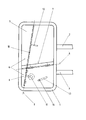
- the invention permits numerous embodiments. To further clarify its basic principle, a left side mirror of a motor vehicle is shown in a highly schematic manner in the drawing and is described below.
- the exterior mirror shown has a mirror housing 1 with two partially shown fastening arms 2, 3.
- a mirror disk 4 is arranged in the mirror housing 1, which consists of two separate mirror surfaces 5, 6, which are separated from one another by a dividing line 7. This dividing line 7 can run horizontally or slightly inclined, as can be seen in the drawing.
- the upper mirror surface 5 can be pivoted about an axis 8 which is also horizontal or slightly inclined with respect to the horizontal, so that when pivoting the upper edge of the mirror surface 5 moves out of the plane of the drawing.
- the lower mirror surface 6 can be pivoted about an axis 9 which is slightly inclined with respect to the vertical. As a result, the right mirror edge moves out of the plane of the drawing when it is pivoted.
- the axis 9 of the exterior mirror is formed by a shaft 10 which is rotatably arranged in the mirror housing 1 and which can be rotated by means of a servomotor 11 which is also arranged in the mirror housing 1 and is designed as a lifting magnet.
- This shaft 10 extends upwards behind the mirror surface 5 and there has a finger 12 which presses against the back of the mirror surface 5 when the shaft 10 is pivoted and therefore pivots it about the axis 8.
- the return movement takes place by a tension spring, not shown, between the mirror surface 5 and the mirror housing 1.
- the mirror surface 6 On its rear side, the mirror surface 6 has a slotted guide 13, seen from the inside out, into which a stationary slide piece 14 of the mirror housing 1 engages. Furthermore, the mirror surface 6 is displaceable on the shaft 10 in the longitudinal direction of the shaft 10, but takes part in its rotational movement. If the mirror surface 6 pivots outwards, then the link guide 13 slides over the slide 14. As a result of the oblique course of the link guide 13, the mirror surface 6 is displaced downward.
- a car exterior mirror which usually differs from an exterior rearview mirror for a truck in that it is considerably wider than it is high and flat. With such an outside mirror, it is expedient if the mirror surface which can be pivoted about the approximately perpendicular axis forms an upper, smaller area of the mirror pane.
Landscapes
- Engineering & Computer Science (AREA)
- Multimedia (AREA)
- Mechanical Engineering (AREA)
- Rear-View Mirror Devices That Are Mounted On The Exterior Of The Vehicle (AREA)
- Optical Elements Other Than Lenses (AREA)
Abstract
Description
- Die Erfindung betrifft einen Außenspiegel für ein Kraftfahrzeug, welcher in einem Spiegelgehäuse eine in zwei Spiegelflächen unterteilte Spiegelscheibe und einen Stellmotor zum Verschwenken einer Spiegelfläche um eine in etwa senkrecht verlaufende, gegenüber einer Innenkante der Spiegelfläche nach außen versetzten Achse hat.
- Ein Außenspiegel der vorstehenden Art ist Gegenstand der GB-A-22 23 724. Bei dem bekannten Spiegel ist die Spiegelscheibe durch eine in etwa senkrecht verlaufende Trennlinie in eine fahrzeuginnenseitige und eine fahrzeugaußenseitige Spiegelfläche aufgeteilt. Bei Betätigung des Richtungsgebers kippt die fahrzeugaußenseitige Spiegelfläche um die senkrechte Achse, so daß ihre äußerste Kante sich nach vorn bewegt. Dadurch wird es dem Fahrzeugführer möglich, mit Hilfe dieser schwenkbaren Spiegelfläche vor einem Spurwechsel einen weiter seitlich liegenden Bereich hinter seinem Fahrzeug zu beobachten als bei nicht verschwenkter Spiegelfläche.
- Außenspiegel der vorstehenden Art konnten sich bislang jedoch in der Praxis nicht durchsetzen, obwohl es immer wieder zu Unfällen beim Überholen kommt, weil vom Ausscherenden ein in seinem "toten Winkel" befindliches, ihn überholendes Fahrzeug nicht gesehen wurde und somit ein sehr großes Bedürfnis nach einem Außenspiegel besteht, der ein Überwachen des "toten Winkels" ermöglicht.
- Der bekannte Außenspiegel ermöglicht insbesondere bei Lastkraftwagen keine ausreichende Überwachung des "toten Winkels", weil ein nahe des Lastkraftwagens seitlich versetzt zu ihm befindliches Fahrzeug sich nicht nur weiter außen, sondern auch in einem schräger nach unten gerichteten Winkel zum Fahrer befindet als ein mit größerem Abstand fahrendes Fahrzeug. Ein zum Überholen eines Lastwagens ansetzender Personenwagen kann sich deshalb nicht nur seitlich des Sichtbereiches eines Spiegels, sondern auch unterhalb dieses Sichtbereiches befinden.
- Der Erfindung liegt das Problem zugrunde, einen Außenspiegel der eingangs genannten Art so zu gestalten, daß eine möglichst weitgehende Beobachtung des rückwärtigen Verkehrs vor einem Überholvorgang möglich ist.
- Dieses Problem wird erfindungsgemäß dadurch gelöst, daß die Spiegelscheibe durch eine in etwa horizontal verlaufende Trennlinie in eine obere Spiegelfläche und eine untere Spiegelfläche unterteilt ist und daß die nicht um die in etwa senkrecht verlaufende Achse verschwenkbare Spiegelfläche um eine in etwa horizontal in der Nähe der Trennungslinie verlaufende Achse schwenkbar ausgebildet ist.
- Bei einem solchen Außenspiegel verschwenken sich im Gegensatz zum Stand der Technik beide Spiegelflächen. Dadurch wird es möglich, zum Überwachen des rückwärtigen Verkehrs nicht nur in einen weiter seitlich liegenden Bereich, sondern auch in einem in der Höhe abweichenden Bereich einzusehen. Praktische Versuche mit dem erfindungsgemäßen Spiegel haben gezeigt, daß er es dem Fahrer vor einem Überholvorgang ermöglicht, sich ohne umzusehen davon zu überzeugen, daß die linke Fahrspur tatsächlich frei ist. Da gemäß der Erfindung von der Spiegelscheibe eine oben oder unten liegende Spiegelfläche um eine in etwa senkrecht liegende Achse verschwenkt wird, könnte man mit der anderen Spiegelfläche weniger weit nach oben oder unten sehen, wenn sie feststehend ausgebildet wäre. Das läßt sich jedoch dank der Erfindung dadurch ausgleichen, daß man die nicht um eine in etwa senkrechte Achse verschwenkbare Spiegelfläche um eine in etwa horizontale Achse verschwenkt und damit mit ihr weiter nach unten oder oben sehen kann.
- Die Verschwenkbarkeit der beiden Spiegelflächen kann auf sehr verschiedene Weise ermöglicht werden. Konstruktiv besonders einfach ist der Außenspiegel gestaltet, wenn gemäß einer vorteilhaften Ausgestaltung der Erfindung die in etwa senkrecht verlaufende Achse durch eine unverdrehbar mit der um sie verschwenkbaren Spiegelfläche verbundene, im Spiegelgehäuse drehbar gelagerte Welle ausgebildet ist, an der der Stellmotor angreift.
- Der Außenspiegel benötigt zur Verschwenkung beider Spiegelflächen nur einen einzigen Stellmotor, wenn gemäß einer anderen Ausgestaltung der Erfindung die Welle bis hinter die um eine in etwa horizontal verlaufende Achse schwenkbare Spiegelfläche führt und hinter dieser Spiegelfläche einen radialen Finger zum Verschwenken dieser Spiegelfläche um ihre in etwa horizontal verlaufende Achse hat.
- Die Spiegelflächen können in nicht verschwenkter Grundstellung sich mit den einander zugewandten Kanten unmittelbar berühren, ohne daß diese Kanten bei Verschwenken stören, wenn die um die in etwa senkrecht verlaufende Achse schwenkbare Spiegelfläche in Vertikalrichtung verschieblich angeordnet ist und auf ihrer Rückseite eine von außen nach innen ansteigende Kulissenführung hat, in welcher ein Gleitstück des Spiegelgehäuses eingreift. Durch diese Gestaltung entfernt sich bei der Schwenkbewegung die eine Spiegelfläche geringfügig von der anderen, so daß der erforderliche Platz für das Kippen der Kanten der Spiegelflächen entsteht.
- Die Verschwenkung der Spiegelflächen beim Setzen und Zurückstellen des Richtungsgebers erfolgt besonders rasch, wenn der Stellmotor ein Hubmagnet ist.
- Für hoch angeordnete Außenspiegel, also für Außenspiegel von Lastkraftwagen, ist eine Ausführungsform der Erfindung vorteilhaft, bei der die um die in etwa senkrecht verlaufende Achse schwenkbare Spiegelfläche einen unteren, kleineren Bereich der Spiegelscheibe bildet.
- Für Personenkraftwagen hat es sich als zweckmäßig herausgestellt, daß die um die in etwa senkrecht verlaufende Achse schwenkbare Spiegelfläche einen oberen, kleineren Bereich der Spiegelscheibe bildet.
- Von Vorteil ist es auch, wenn für ein hohes Fahrzeug die in etwa senkrecht verlaufende Achse an der Spiegeloberseite geringeren seitlichen Abstand vom Kraftfahrzeug hat als an der Spiegelunterseite. Hierdurch wird bei einem Lastkraftwagen oder Bus die untere Spiegelfläche beim Herausschwenken derart verkippt, daß man mit ihr nicht nur weiter seitlich, sondern auch weiter nach hinten schauen kann.
- Im Gegensatz zur vorgenannten Ausführungsform ist es bei niedrigen Fahrzeugen, also bei Personenkraftwagen günstig, wenn die in etwa senkrecht verlaufende Achse an der Spiegeloberseite größeren seitlichen Abstand vom Kraftfahrzeug hat als an der Spiegelunterseite, damit man ebenfalls mit der herausgeschwenkten Spiegelfläche einen weiter im Hintergrund liegenden Bereich beobachten kann.
- Die Erfindung läßt zahlreiche Ausführungsformen zu. Zur weiteren Verdeutlichung ihres Grundprinzips ist in der Zeichnung stark schematisch ein linker Außenspiegel eines Kraftfahrzeugs dargestellt und wird nachfolgend beschrieben.
- Der dargestellte Außenspiegel hat ein Spiegelgehäuse 1 mit zwei teilweise dargestellten Befestigungsarmen 2, 3. Im Spiegelgehäuse 1 ist eine Spiegelscheibe 4 angeordnet, welche aus zwei separaten Spiegelflächen 5, 6 besteht, die durch eine Trennlinie 7 voneinander getrennt sind. Diese Trennlinie 7 kann horizontal oder leicht geneigt verlaufen, wie das in der Zeichnung zu erkennen ist.
- Wichtig für die Erfindung ist, daß die obere Spiegelfläche 5 um eine ebenfalls horizontal oder gegenüber der Horizontalen leicht geneigt verlaufenden Achse 8 schwenkbar ist, so daß beim Verschwenken die obere Kante der Spiegelfläche 5 sich aus der Zeichnungsebene heraus bewegt. Die untere Spiegelfläche 6 ist um eine gegenüber der Senkrechten leicht geneigten Achse 9 schwenkbar. Dadurch bewegt sich bei ihr beim Verschwenken die rechte Spiegelkante aus der Zeichnungsebene heraus.
- Zur Vereinfachung der Darstellung sind auch die hinter der Spiegelscheibe 4 angeordneten Teile des Außenspiegels sichtbar dargestellt. Die Achse 9 des Außenspiegels ist durch eine drehbar im Spiegelgehäuse 1 angeordnete Welle 10 gebildet, welche mittels eines ebenfalls im Spiegelgehäuse 1 angeordneten, als Hubmagnet ausgebildeten Stellmotors 11 verdreht werden kann. Diese Welle 10 reicht nach oben bis hinter die Spiegelfläche 5 und hat dort einen Finger 12, der bei einem Verschwenken der Welle 10 gegen die Rückseite der Spiegelfläche 5 drückt und diese deshalb um die Achse 8 verschwenkt. Die Rückbewegung erfolgt durch eine nicht gezeigte Zugfeder zwischen der Spiegelfläche 5 und dem Spiegelgehäuse 1.
- Die Spiegelfläche 6 hat an ihrer Rückseite eine von innen nach außen gesehen abfallende Kulissenführung 13, in die ein ortsfestes Gleitstück 14 des Spiegelgehäuses 1 greift. Weiterhin ist die Spiegelfläche 6 auf der Welle 10 in Längsrichtung der Welle 10 verschieblich, nimmt jedoch an ihrer Drehbewegung teil. Schwenkt die Spiegelfläche 6 nach außen, dann gleitet die Kulissenführung 13 über das Gleitstück 14. Infolge des schrägen Verlaufs der Kulissenführung 13 wird dabei die Spiegelfläche 6 nach unten verschoben.
- Nicht dargestellt ist ein PKW-Außenspiegel, welcher sich von einem Außenrückspiegel für einen LKW meist dadurch unterscheidet, daß er wesentlich breiter als hoch und plan ist. Bei einem solchen Außenspiegel ist es zweckmäßig, wenn die um die in etwa senkrecht verlaufende Achse schwenkbare Spiegelfläche einen oberen, kleineren Bereich der Spiegelscheibe bildet.
-
- 1 Spiegelgehäuse
- 2 Befestigungsarm
- 3 Befestigungsarm
- 4 Spiegelscheibe
- 5 Spiegelfläche
- 6 Spiegelfläche
- 7 Trennlinie
- 8 Achse
- 9 Achse
- 10 Welle
- 11 Stellmotor
- 12 Finger
- 13 Kulissenführung
- 14 Gleitstück
Claims (9)
Applications Claiming Priority (2)
| Application Number | Priority Date | Filing Date | Title |
|---|---|---|---|
| DE9402385 | 1994-02-14 | ||
| DE9402385U | 1994-02-14 |
Publications (2)
| Publication Number | Publication Date |
|---|---|
| EP0667259A1 true EP0667259A1 (de) | 1995-08-16 |
| EP0667259B1 EP0667259B1 (de) | 1999-06-02 |
Family
ID=6904534
Family Applications (1)
| Application Number | Title | Priority Date | Filing Date |
|---|---|---|---|
| EP95101857A Expired - Lifetime EP0667259B1 (de) | 1994-02-14 | 1995-02-10 | Aussenspiegel für ein Kraftfahrzeug |
Country Status (5)
| Country | Link |
|---|---|
| US (1) | US5631781A (de) |
| EP (1) | EP0667259B1 (de) |
| DE (1) | DE59506060D1 (de) |
| DK (1) | DK0667259T3 (de) |
| ES (1) | ES2134365T3 (de) |
Families Citing this family (2)
| Publication number | Priority date | Publication date | Assignee | Title |
|---|---|---|---|---|
| CN1191822A (zh) * | 1997-02-19 | 1998-09-02 | 不列特斯基科有限公司 | 车辆外部后视镜 |
| GB2373231A (en) * | 2001-03-16 | 2002-09-18 | Fathollah Naini Emami | Wing mirror assembly incuding blind spot mirror |
Citations (9)
| Publication number | Priority date | Publication date | Assignee | Title |
|---|---|---|---|---|
| DE2409748A1 (de) * | 1974-03-01 | 1975-09-04 | Inpat Gmbh & Co | Rueckspiegel fuer kraftfahrzeuge |
| EP0028860A1 (de) * | 1979-11-09 | 1981-05-20 | André Guillaume | Aussenrückspiegel |
| DE3302735A1 (de) * | 1983-01-27 | 1984-08-02 | geb. Hartwig Johanne 6237 Liederbach Schulze | Aussenrueckspiegel fuer kraftfahrzeuge |
| US4715701A (en) * | 1986-07-23 | 1987-12-29 | Urban Milfred W | Mirror and bracket assembly |
| DE3806579A1 (de) * | 1988-02-26 | 1989-09-07 | Horst Kraemer | Fahrzeug-aussenrueckblickspiegel fuer normalen und zusaetzlichen sehbereich |
| US4932770A (en) * | 1988-12-20 | 1990-06-12 | Caravaty Raymond D | Dual plane rear vision mirror |
| FR2650982A1 (fr) * | 1989-08-18 | 1991-02-22 | Silvestre Aime | Retroviseurs exterieurs situes du cote du conducteur |
| DE3931485A1 (de) * | 1989-09-21 | 1991-04-04 | Seefluth Uwe Christian | Aussenrueckspiegel fuer kraftfahrzeuge |
| EP0443990A1 (de) * | 1990-02-23 | 1991-08-28 | Giovanni Battista Musinu | Rückspiegel für Motorfahrzeuge und allgemeine Transportmittel mit zweiteiliger Oberfläche für doppelte Blickrichtung |
Family Cites Families (6)
| Publication number | Priority date | Publication date | Assignee | Title |
|---|---|---|---|---|
| US4678294A (en) * | 1985-12-03 | 1987-07-07 | Nostrand Willard R Van | Mirror assembly for determining distance to passed vehicle |
| GB2223724A (en) * | 1988-09-24 | 1990-04-18 | Benjamin Peter Corrigan | Dual angle rear view mirror |
| US4929074A (en) * | 1988-10-24 | 1990-05-29 | Urban Milfred W | Mirror and bracket assembly |
| BR8900142A (pt) * | 1989-01-10 | 1990-08-14 | Metagal Industria E Comercio Ltda. | Aperfeicoamentos em espelho retrovisor externo para veiculos |
| US5052792A (en) * | 1990-04-16 | 1991-10-01 | Mcdonough Michael J | Selectively positionable rear view mirror system for vehicles with two mirror segments and control circuit cooperating with turn signal system |
| US5295021A (en) * | 1993-04-19 | 1994-03-15 | Arthur P. Swanson | Triple exterior rearview vehicle mirror |
-
1995
- 1995-02-10 EP EP95101857A patent/EP0667259B1/de not_active Expired - Lifetime
- 1995-02-10 ES ES95101857T patent/ES2134365T3/es not_active Expired - Lifetime
- 1995-02-10 DE DE59506060T patent/DE59506060D1/de not_active Expired - Fee Related
- 1995-02-10 DK DK95101857T patent/DK0667259T3/da active
- 1995-02-14 US US08/388,036 patent/US5631781A/en not_active Expired - Fee Related
Patent Citations (9)
| Publication number | Priority date | Publication date | Assignee | Title |
|---|---|---|---|---|
| DE2409748A1 (de) * | 1974-03-01 | 1975-09-04 | Inpat Gmbh & Co | Rueckspiegel fuer kraftfahrzeuge |
| EP0028860A1 (de) * | 1979-11-09 | 1981-05-20 | André Guillaume | Aussenrückspiegel |
| DE3302735A1 (de) * | 1983-01-27 | 1984-08-02 | geb. Hartwig Johanne 6237 Liederbach Schulze | Aussenrueckspiegel fuer kraftfahrzeuge |
| US4715701A (en) * | 1986-07-23 | 1987-12-29 | Urban Milfred W | Mirror and bracket assembly |
| DE3806579A1 (de) * | 1988-02-26 | 1989-09-07 | Horst Kraemer | Fahrzeug-aussenrueckblickspiegel fuer normalen und zusaetzlichen sehbereich |
| US4932770A (en) * | 1988-12-20 | 1990-06-12 | Caravaty Raymond D | Dual plane rear vision mirror |
| FR2650982A1 (fr) * | 1989-08-18 | 1991-02-22 | Silvestre Aime | Retroviseurs exterieurs situes du cote du conducteur |
| DE3931485A1 (de) * | 1989-09-21 | 1991-04-04 | Seefluth Uwe Christian | Aussenrueckspiegel fuer kraftfahrzeuge |
| EP0443990A1 (de) * | 1990-02-23 | 1991-08-28 | Giovanni Battista Musinu | Rückspiegel für Motorfahrzeuge und allgemeine Transportmittel mit zweiteiliger Oberfläche für doppelte Blickrichtung |
Also Published As
| Publication number | Publication date |
|---|---|
| DK0667259T3 (da) | 1999-12-13 |
| EP0667259B1 (de) | 1999-06-02 |
| US5631781A (en) | 1997-05-20 |
| DE59506060D1 (de) | 1999-07-08 |
| ES2134365T3 (es) | 1999-10-01 |
Similar Documents
| Publication | Publication Date | Title |
|---|---|---|
| DE3345122C2 (de) | Fahrzeugschiebedach | |
| DE3124325C2 (de) | ||
| DE3211794A1 (de) | Aussenrueckspiegel fuer kraftfahrzeuge | |
| EP0231924B1 (de) | Elektrischer Schalter, insbesondere Lenkstockschalter für Kraftfahrzeuge | |
| DE2701706C3 (de) | Fensteranordnung für Kraftfahrzeuge | |
| DE2624061C3 (de) | An einem zu öffnenden Fahrzeugkabinenfenster angebrachte Scheibenwischeranlage | |
| DE3222861A1 (de) | Blendschutzvorrichtung fuer mit einer versenkbaren seitenscheibe ausgeruestete fahrzeuge | |
| EP0667259A1 (de) | Aussenspiegel für ein Kraftfahrzeug | |
| DE8512360U1 (de) | Schiebehebedach für Fahrzeuge | |
| DE1988401U (de) | Aschenbehaelter fuer fahrzeuge. | |
| EP0212176B1 (de) | Kraftfahrzeug mit Leuchtenschutzvorrichtung | |
| EP0222064A2 (de) | Fahrzeugspiegel | |
| EP0141145B1 (de) | Anlenkvorrichtung für ein klappbares Karosserieteil an einem Kfz., inbes. für einen Gepäckraumdeckel an einer PKW-Karosserie | |
| DE2218335A1 (de) | Sich selbsttätig abstellender Blinkschalter | |
| DE3532095A1 (de) | Schiebedach fuer fahrzeuge | |
| EP0292960A2 (de) | Kraftfahrzeugtür, insbesondere für Personenkraftwagen | |
| DE2406381A1 (de) | Abblendbarer innenrueckblickspiegel | |
| DE3401033A1 (de) | Inneres autospiegelsystem ohne toten winkel | |
| EP0255139B1 (de) | Kraftfahrzeug, insbesondere Personenkraftwagen, mit in die flach verlaufende Fahrzeugbugdeckwand eingelassen angeordneten Scheinwerfern | |
| DE2937543A1 (de) | Verstellbarer rueckspiegel fuer kraftfahrzeuge | |
| EP0849105B1 (de) | Öffnungsfähiger Deckel, insbesondere für ein Fahrzeug | |
| DE754363C (de) | Abdunkelungsvorrichtung fuer Fahrzeugscheinwerfer | |
| DE225786C (de) | ||
| DE3710429A1 (de) | Sonnenblende fuer kraftfahrzeuge | |
| DE1062130B (de) | Anordnung zum Verhindern der Blendwirkung durch Scheinwerfer od. dgl. |
Legal Events
| Date | Code | Title | Description |
|---|---|---|---|
| PUAI | Public reference made under article 153(3) epc to a published international application that has entered the european phase |
Free format text: ORIGINAL CODE: 0009012 |
|
| AK | Designated contracting states |
Kind code of ref document: A1 Designated state(s): BE DE DK ES FR GB IT NL SE |
|
| 17P | Request for examination filed |
Effective date: 19960217 |
|
| 17Q | First examination report despatched |
Effective date: 19970704 |
|
| GRAG | Despatch of communication of intention to grant |
Free format text: ORIGINAL CODE: EPIDOS AGRA |
|
| GRAG | Despatch of communication of intention to grant |
Free format text: ORIGINAL CODE: EPIDOS AGRA |
|
| GRAH | Despatch of communication of intention to grant a patent |
Free format text: ORIGINAL CODE: EPIDOS IGRA |
|
| GRAH | Despatch of communication of intention to grant a patent |
Free format text: ORIGINAL CODE: EPIDOS IGRA |
|
| GRAA | (expected) grant |
Free format text: ORIGINAL CODE: 0009210 |
|
| AK | Designated contracting states |
Kind code of ref document: B1 Designated state(s): BE DE DK ES FR GB IT NL SE |
|
| REF | Corresponds to: |
Ref document number: 59506060 Country of ref document: DE Date of ref document: 19990708 |
|
| ITF | It: translation for a ep patent filed | ||
| GBT | Gb: translation of ep patent filed (gb section 77(6)(a)/1977) |
Effective date: 19990907 |
|
| ET | Fr: translation filed | ||
| REG | Reference to a national code |
Ref country code: ES Ref legal event code: FG2A Ref document number: 2134365 Country of ref document: ES Kind code of ref document: T3 |
|
| REG | Reference to a national code |
Ref country code: DK Ref legal event code: T3 |
|
| PGFP | Annual fee paid to national office [announced via postgrant information from national office to epo] |
Ref country code: FR Payment date: 20000218 Year of fee payment: 6 |
|
| PGFP | Annual fee paid to national office [announced via postgrant information from national office to epo] |
Ref country code: SE Payment date: 20000221 Year of fee payment: 6 Ref country code: GB Payment date: 20000221 Year of fee payment: 6 |
|
| PGFP | Annual fee paid to national office [announced via postgrant information from national office to epo] |
Ref country code: DK Payment date: 20000224 Year of fee payment: 6 |
|
| PGFP | Annual fee paid to national office [announced via postgrant information from national office to epo] |
Ref country code: ES Payment date: 20000228 Year of fee payment: 6 |
|
| PGFP | Annual fee paid to national office [announced via postgrant information from national office to epo] |
Ref country code: NL Payment date: 20000229 Year of fee payment: 6 |
|
| PGFP | Annual fee paid to national office [announced via postgrant information from national office to epo] |
Ref country code: BE Payment date: 20000317 Year of fee payment: 6 |
|
| PLBE | No opposition filed within time limit |
Free format text: ORIGINAL CODE: 0009261 |
|
| STAA | Information on the status of an ep patent application or granted ep patent |
Free format text: STATUS: NO OPPOSITION FILED WITHIN TIME LIMIT |
|
| 26N | No opposition filed | ||
| PG25 | Lapsed in a contracting state [announced via postgrant information from national office to epo] |
Ref country code: GB Free format text: LAPSE BECAUSE OF NON-PAYMENT OF DUE FEES Effective date: 20010210 Ref country code: DK Free format text: LAPSE BECAUSE OF NON-PAYMENT OF DUE FEES Effective date: 20010210 |
|
| PG25 | Lapsed in a contracting state [announced via postgrant information from national office to epo] |
Ref country code: SE Free format text: LAPSE BECAUSE OF NON-PAYMENT OF DUE FEES Effective date: 20010211 |
|
| PG25 | Lapsed in a contracting state [announced via postgrant information from national office to epo] |
Ref country code: ES Free format text: LAPSE BECAUSE OF NON-PAYMENT OF DUE FEES Effective date: 20010212 |
|
| PG25 | Lapsed in a contracting state [announced via postgrant information from national office to epo] |
Ref country code: BE Free format text: LAPSE BECAUSE OF NON-PAYMENT OF DUE FEES Effective date: 20010228 |
|
| BERE | Be: lapsed |
Owner name: HARTMANN HELMUT Effective date: 20010228 |
|
| PG25 | Lapsed in a contracting state [announced via postgrant information from national office to epo] |
Ref country code: NL Free format text: LAPSE BECAUSE OF NON-PAYMENT OF DUE FEES Effective date: 20010901 |
|
| REG | Reference to a national code |
Ref country code: DK Ref legal event code: EBP |
|
| GBPC | Gb: european patent ceased through non-payment of renewal fee |
Effective date: 20010210 |
|
| EUG | Se: european patent has lapsed |
Ref document number: 95101857.1 |
|
| PG25 | Lapsed in a contracting state [announced via postgrant information from national office to epo] |
Ref country code: FR Free format text: LAPSE BECAUSE OF NON-PAYMENT OF DUE FEES Effective date: 20011031 |
|
| NLV4 | Nl: lapsed or anulled due to non-payment of the annual fee |
Effective date: 20010901 |
|
| REG | Reference to a national code |
Ref country code: FR Ref legal event code: ST |
|
| REG | Reference to a national code |
Ref country code: ES Ref legal event code: FD2A Effective date: 20021116 |
|
| PG25 | Lapsed in a contracting state [announced via postgrant information from national office to epo] |
Ref country code: IT Free format text: LAPSE BECAUSE OF NON-PAYMENT OF DUE FEES;WARNING: LAPSES OF ITALIAN PATENTS WITH EFFECTIVE DATE BEFORE 2007 MAY HAVE OCCURRED AT ANY TIME BEFORE 2007. THE CORRECT EFFECTIVE DATE MAY BE DIFFERENT FROM THE ONE RECORDED. Effective date: 20050210 |
|
| PGFP | Annual fee paid to national office [announced via postgrant information from national office to epo] |
Ref country code: DE Payment date: 20050825 Year of fee payment: 11 |
|
| PG25 | Lapsed in a contracting state [announced via postgrant information from national office to epo] |
Ref country code: DE Free format text: LAPSE BECAUSE OF NON-PAYMENT OF DUE FEES Effective date: 20060901 |