EP0667292A2 - Formkörper zur Aufnahme und Verpackung von Gegenständen - Google Patents
Formkörper zur Aufnahme und Verpackung von Gegenständen Download PDFInfo
- Publication number
- EP0667292A2 EP0667292A2 EP95100476A EP95100476A EP0667292A2 EP 0667292 A2 EP0667292 A2 EP 0667292A2 EP 95100476 A EP95100476 A EP 95100476A EP 95100476 A EP95100476 A EP 95100476A EP 0667292 A2 EP0667292 A2 EP 0667292A2
- Authority
- EP
- European Patent Office
- Prior art keywords
- shaped body
- side walls
- folds
- body according
- edges
- Prior art date
- Legal status (The legal status is an assumption and is not a legal conclusion. Google has not performed a legal analysis and makes no representation as to the accuracy of the status listed.)
- Granted
Links
- 238000004806 packaging method and process Methods 0.000 title claims description 3
- 238000005192 partition Methods 0.000 claims abstract description 19
- 239000000463 material Substances 0.000 claims description 5
- 229920002678 cellulose Polymers 0.000 claims description 2
- 239000001913 cellulose Substances 0.000 claims description 2
- 239000000123 paper Substances 0.000 claims description 2
- 238000007789 sealing Methods 0.000 claims description 2
- 239000012778 molding material Substances 0.000 abstract description 4
- 239000003292 glue Substances 0.000 abstract description 2
- 239000000853 adhesive Substances 0.000 description 2
- 230000001070 adhesive effect Effects 0.000 description 2
- 238000010112 shell-mould casting Methods 0.000 description 2
- 230000004308 accommodation Effects 0.000 description 1
- 238000004519 manufacturing process Methods 0.000 description 1
- 238000002604 ultrasonography Methods 0.000 description 1
Images


Classifications
-
- B—PERFORMING OPERATIONS; TRANSPORTING
- B65—CONVEYING; PACKING; STORING; HANDLING THIN OR FILAMENTARY MATERIAL
- B65D—CONTAINERS FOR STORAGE OR TRANSPORT OF ARTICLES OR MATERIALS, e.g. BAGS, BARRELS, BOTTLES, BOXES, CANS, CARTONS, CRATES, DRUMS, JARS, TANKS, HOPPERS, FORWARDING CONTAINERS; ACCESSORIES, CLOSURES, OR FITTINGS THEREFOR; PACKAGING ELEMENTS; PACKAGES
- B65D5/00—Rigid or semi-rigid containers of polygonal cross-section, e.g. boxes, cartons or trays, formed by folding or erecting one or more blanks made of paper
- B65D5/20—Rigid or semi-rigid containers of polygonal cross-section, e.g. boxes, cartons or trays, formed by folding or erecting one or more blanks made of paper by folding-up portions connected to a central panel from all sides to form a container body, e.g. of tray-like form
- B65D5/24—Rigid or semi-rigid containers of polygonal cross-section, e.g. boxes, cartons or trays, formed by folding or erecting one or more blanks made of paper by folding-up portions connected to a central panel from all sides to form a container body, e.g. of tray-like form with adjacent sides interconnected by gusset folds
- B65D5/241—Rigid or semi-rigid containers of polygonal cross-section, e.g. boxes, cartons or trays, formed by folding or erecting one or more blanks made of paper by folding-up portions connected to a central panel from all sides to form a container body, e.g. of tray-like form with adjacent sides interconnected by gusset folds and the gussets folds connected to the inside of the container body
- B65D5/243—Rigid or semi-rigid containers of polygonal cross-section, e.g. boxes, cartons or trays, formed by folding or erecting one or more blanks made of paper by folding-up portions connected to a central panel from all sides to form a container body, e.g. of tray-like form with adjacent sides interconnected by gusset folds and the gussets folds connected to the inside of the container body the container body comprising a continuous rim or flange
-
- B—PERFORMING OPERATIONS; TRANSPORTING
- B65—CONVEYING; PACKING; STORING; HANDLING THIN OR FILAMENTARY MATERIAL
- B65D—CONTAINERS FOR STORAGE OR TRANSPORT OF ARTICLES OR MATERIALS, e.g. BAGS, BARRELS, BOTTLES, BOXES, CANS, CARTONS, CRATES, DRUMS, JARS, TANKS, HOPPERS, FORWARDING CONTAINERS; ACCESSORIES, CLOSURES, OR FITTINGS THEREFOR; PACKAGING ELEMENTS; PACKAGES
- B65D5/00—Rigid or semi-rigid containers of polygonal cross-section, e.g. boxes, cartons or trays, formed by folding or erecting one or more blanks made of paper
- B65D5/42—Details of containers or of foldable or erectable container blanks
- B65D5/44—Integral, inserted or attached portions forming internal or external fittings
- B65D5/48—Partitions
- B65D5/48002—Partitions integral
- B65D5/48022—Partitions integral formed by two parallel panels located in the base of a tray being folded up towards each other
Definitions
- the entire invention relates to a shaped body suitable for receiving and packaging objects, which is made from a cellulose material such as cardboard, paper, parchment or the like by folding the same and has the shape of an upwardly open shell or. The like., In which in each case located in the corner areas excess molding material a reduction of the same effecting folds are introduced, which are folded against the outside or inside of the raised side walls and attached to them.
- the object of the present invention is now to eliminate this still existing disadvantage and to create a shaped body which is suitable for the separate accommodation of different objects, goods or the like.
- the molded body has a plurality of compartments and is designed as a shell or the like formed from a single blank, the partition walls between the compartments of which are formed by double folding the blank, in which between these partition walls and These adjacent side walls are also provided with corner folds which reduce the excess molding material, can be folded over against the outer or inner sides of the raised side walls and fastened to them. It is particularly important that only a single blank is required for such a tray or the like having multiple compartments.
- the fold lines of the folds made in the corner areas expediently form an angle of 30 to 60 ° with the adjacent edges of the partition walls, but in particular an angle of 45 if it is in the latter case it is a substantially rectangular shell.
- FIG. 1 shows the diagrammatic representation of a shell-shaped molded body 1 which has three compartments 2 to 4 which are adjacent to one another and which are separated from one another by partitions designated 5 and 6. Each of these three compartments 2 to 4 is designed as a partial shell 7 to 9, these partial shells 7 to 9 being connected to one another again via the partition walls 5 and 6 already mentioned.
- the outer side walls of these partial shells 7 to 9 are designated by 10 to 12, 13 and 14 and 15 to 17.
- this molded body 1 has a continuous, outwardly projecting edge 18, which serves as a support for a cover, which is not particularly shown, and which covers the entire molded body 1. This edge 18 is again formed from mutually overlapping partial edges 19 to 26 formed on the side walls 10 to 17.
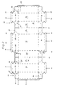
- This blank 27 has three adjacent blank parts, labeled 28 to 30, which are connected to one another along the fold lines labeled 31 and 32 are.
- each of these three cut parts 28 to 30 each has a base designated 33, to which the associated side walls 10 to 12, 13 and 14 and 15 to 17 then adjoin.
- these three base parts 33 are each connected to one another by means of mutually adjacent partition wall parts 34 and 35.
- an obliquely outwardly directed folding line 37 is incorporated, which includes an angle x of 45 with the edge 38 of the respectively adjacent side wall 10 to 17.
- the side walls 10 to 17 and the partition wall parts 34 and 35 of the partial shells 7, 8 and 9 are raised by 90 ° in the usual manner.
- these corner regions 36 are folded along their fold line 37, as a result of which folds which are directed outwards and are designated by 39 are produced.
- These folds 39 are then folded in the direction of the arrows 40 against the outer sides of the respectively associated side walls 10 to 17 and glued to the latter by means of an adhesive to be activated, for example, by ultrasound.
- These folds 39 are triangular and each have a blunt end edge 41, which are formed by corresponding cutouts 42.
- the partial edges 19 to 26 are also bent by 90 ° into their horizontal position shown in FIG. 1, the ends of these partial edges 19 to 26 designated by 43 then being bent in that shown in FIG Way overlap each other.
- These partial edge ends 43 are also connected to one another by means of a suitable adhesive in such a way that these partial edges 19 to 26 form a rigid edge 18 suitable as a support for the previously mentioned, not particularly illustrated cover.
- partition wall parts 34 and 35 When the partition wall parts 34 and 35 are raised, they are folded over along their fold lines 31 and 32 to form a double fold forming the two partition walls 5 and 6, respectively.
- the cardboard provided for the blank 27 is plastic-coated and the fold lines incorporated into the blank are only grooved, the three cup-shaped, adjacent compartments 2 to 4 are also liquid-tight.
- the molded body 52 shown in FIG. 3 with its side walls 45 to 48 has dividing walls 43, 44 running at an angle to the side surfaces 46, 48.
- three trapezoidal partial shells 49, 50 and 51 are formed, which can be used to insert specially designed parts.
- the longitudinal side walls 46, 48 are designed without edges and any sealing film (not shown) that may be provided can then be attached to the side parts of these walls.
Landscapes
- Engineering & Computer Science (AREA)
- Mechanical Engineering (AREA)
- Cartons (AREA)
- Packaging Of Special Articles (AREA)
- Making Paper Articles (AREA)
Abstract
Description
- Die voliegende Erfindung hat einen zur Aufnahme und Verpackung von Gegenständen geeigneten Formkörper zum Gegenstand, der aus einem aus Zellulosewerkstoff wie beispielsweise Pappe, Papier, Pergament od. dgl. bestehenden Zuschitt durch Faltung desselben hergestellt ist und die Gestalt einer nach oben hin offenen Schale od. dgl. aufweist, wobei in das jeweils in den Eckbereichen befindliche überschüssige Formkörpermaterial eine Reduzierung desselben bewirkende Einschlagfalten eingebracht sind, die gegen die Außen- oder Innenseiten der hochgestellten Seitenwände umgeklappt und an diesen befestigt sind.
- Es sind bereits einschalige Formkörper der zuvor erwähnten Art bekannt, bei denen in das in den Eckbereichen überstehende überschüssige Formkörpermaterial nach außen vorstehende Doppelfalten eingebracht sind, die nach dem Hochstellen der Seitenwände gegen deren Außenseiten abgebogen und an denselben angeklebt worden sind.
- Diese einschaligen Formkörper sind jedoch immer dann nicht ausreichend, wenn in denselben mehrere unterschiedliche Gegenstände od. dgl. untergebracht werden sollen und diese voneinander getrennt zu halten sind.
- Aufgabe der vorliegenden Erfindung ist es nunmehr, diesen immer noch bestehenden Nachteil zu beseitigen und ein Formkörper zu schaffen, der für die getrennte Unterbringung unterschiedlicher Gegenstände, Waren od. dgl. geeignet ist.
- Diese Aufgabe wird erfindungsgemäß nun dadurch gelöst, daß der Formkörper mehrere Fächer aufweist und als eine aus einem einzigen Zuschnitt gebildete Schale od. dgl. ausgestaltet ist, deren zwischen den Fächern befindlichen Trennwände durch Doppelfalten des Zuschnittes gebildet sind, in dessen zwischen diesen Trennwänden und den diesen benachbarten Seitenwänden befindlichen Eckbereichen desgleichen das überschüssige Formkörpermaterial reduzierende, gegen die Außen- oder Innenseiten der hochgestellten Seitenwände umklappbare und an diesen zu befestigende Einschlagfalten eingebracht sind. Besonders bedeutsam ist es dabei, daß auch für eine solche mehrere Fächer aufweisende Schale od. dgl. nur ein einziger Zuschnitt benötigt wird.
- Weist der schalenartige Formkörper einen horizontalen Boden und gegenüber diesem hochgestellte Seitenwände auf, so schließen die Faltlinien der in den Eckbereichen eingebrachten Einschlagfalten mit den benachbarten Kanten der Trennwände zweckmäßig einen Winkel von 30 bis 60°, insbesondere aber einen Winkel von 45 ein, wenn es sich im letzteren Fall um eine im wesentliche rechteckige Schale handelt.
- Darüber hinaus ist es noch zweckmäßig, wenn an den Oberkanten der Trennwände nach außen vorstehende Randleisten od. dgl. angeformt sind, die eine durchgehende, sich über den gesamten Rand der Schale erstreckenden Auflage für einen auf dieselbe aufzulegenden, das Fach mindestens teilweise abdeckenden Deckel bilden.
- Weitere Einzelheiten der vorliegenden Erfindung sind der folgenden Beschreibung einer beispielsweisen Ausführungsform sowie den nachgestellten Ansprüchen zu entnehmen. Es zeigen:
- Figur 1 die schaubildliche Darstellung eines schalenförmigen, drei Fächer aufweisenden Formkörpers und
- Figur 2 die Draufsicht eines für die Herstellung dieses Formkörpers geeigneten Zuschnittes.
- Figur 3 eine Darstellung nach Figur 1 eines anderen Formkörpers.
- Die Figur 1 zeigt die schaubildliche Darstellung eines schalenförmigen Formkörpers 1, der drei einander benachbarte Fächer 2 bis 4 aufweist, die durch mit 5 und 6 bezeichnete Trennwände gegeneinander abgeteilt sind. Jedes dieser drei Fächer 2 bis 4 ist dabei als Teilschale 7 bis 9 ausgebildet, wobei diese Teilschalen 7 bis 9 wieder über die zuvor schon erwähnten Trennwände 5 und 6 miteinander verbunden sind. Die äußeren Seitenwände dieser Teilschalen 7 bis 9 sind dabei mit 10 bis 12, 13 und 14 sowie 15 bis 17 bezeichnet. Darüber hinaus weist dieser Formkörper 1 einen durchgehenden, nach außen vorstehenden Rand 18 auf, der als Auflager für einen nicht besonders dargestellten, den gesamten Formkörper 1 abdeckenden Deckel dient. Dieser Rand 18 wird dabei wieder aus sich gegenseitig überlappenden, an den Seitenwänden 10 bis 17 angeformten Teilrändern 19 bis 26 gebildet.
- Zur Herstellung dieses Formkörpers 1 dient ein einziger, in Figur 2 in Draufsicht dargestellter und aus Pappe bestehender Zuschnitt 27. Dieser Zuschnitt 27 weist dabei drei einander benachbarte, mit 28 bis 30 bezeichnete Zuschnitteile auf, die längs der mit 31 und 32 bezeichneten Faltlinien miteinander verbunden sind. Zur Bildung der zuvor erwähnten Teilschalen 7 bis 9 hat jeder dieser drei Zuschnitteile 28 bis 30 jeweils einen mit 33 bezeichneten Boden, an den sich dann die zugehörigen Seitenwände 10 bis 12, 13 und 14 sowie 15 bis 17 anschließen. Außerdem sind diese drei Bodenteile 33 jeweils mittels paarweise einander benachbarten Trennwandteilen 34 und 35 miteinander verbunden. Schließlich ist in den zwischen den Seitenwänden 10 bis 17 und den Trennwandteilen 34 und 35 befindlichen Eckbereichen 36 jeweils eine schräg nach außen gerichtete Faltlinie 37 eingearbeitet, die mit der Kante 38 der jeweils benachbarten Seitenwand 10 bis 17 einen Winkel x von 45 einschließt.
- Um nun aus diesem zuvor ausführlich behandelten Zuschnitt 27 den in Figur 1 dargestellten Formkörper 1 herzustellen, werden in der üblichen Weise die Seitenwände 10 bis 17 sowie die Trennwandteile 34 und 35 der Teilschalen 7, 8 und 9 um 90 ° hochgestellt. Um ferner das in den Eckbereichen 36 befindliche Formkörpermaterial zu verdrängen, werden diese Eckbereiche 36 längs ihrer Faltlinie 37 gefaltet, wodurch nach außen gerichtete und mit 39 bezeichnete Einschlagfalten entstehen. Diese Einschlagfalten 39 werden sodann in Richtung der Pfeile 40 gegen die Außenseiten der jeweils zugehörigen Seitenwände 10 bis 17 geklappt und mittels eines beispielsweise durch Ultraschall zu aktivierenden Klebers an diesen angeklebt. Diese Einschlagfalten 39 sind dreiecksförmig und weisen jeweils eine stumpfe Endkante 41 auf, die dabei durch entsprechende Ausschnitte 42 gebildet sind.
- Gleichzeitig mit dem Hochstellen der Seitenwände 10 bis 17 werden auch die Teilränder 19 bis 26 um 90 ° in ihre in der Figur 1 gezeigte horizontale Lage umgebogen, wobei sich dann die mit 43 bezeichneten Enden dieser Teilränder 19 bis 26 in der in der Figur 1 gezeigten Weise einander überlappen. Auch diese Teilrandenden 43 werden mittels eines geeigneten Klebers so miteinander verbunden, das diese Teilränder 19 bis 26 einen als Auflage für den zuvor schon erwähnten, nicht besonders dargestellten Deckel geeigneten steifen Rand 18 bilden.
- Bei dem Hochstellen der Trennwandteile 34 und 35 werden diese längs ihrer Faltlinien 31 bzw. 32 jeweils zu einer die beiden Trennwände 5 bzw. 6 bildenden Doppelfalte umgeschlagen. Um hierbei dem Formkörper 1 die notwendige Steifigkeit zu verleihen, ist es vorteilhaft, die einander gegenüberliegenden Innenseiten dieser Trennwandteile 34/35 miteinander zu verkleben.
- Da die für den Zuschnitt 27 vorgesehene Pappe kunststoffbeschichtet und die in den Zuschnitt eingearbeiteten Faltlinien nur gerillt sind, sind die drei schalenförmigen, einander benachbarten Fächer 2 bis 4 auch flüssigkeitsdicht.
- Der in Figur 3 dargestellte Formkörper 52 mit seinen Seitenwänden 45 bis 48 weist in einem Winkel zu den Seitenflächen 46, 48 verlaufende Trennwände 43, 44 auf. Dadurch werden drei trapezförmige Teilschalen 49, 50 und 51 gebildet, welche zum Einsetzen von besonders gestalteten Teilen dienen können.
- Um die Oberfläche des Formkörpers 52 möglichst klein zu halten sind die Längsseitenwände 46, 48 randfrei ausgebildet und eine etwa vorgesehene nicht dargestellte Versiegelungsfolie kann dann an den Seitenteilen dieser Wände festgelegt werden.
Claims (10)
Applications Claiming Priority (2)
| Application Number | Priority Date | Filing Date | Title |
|---|---|---|---|
| DE9401595U DE9401595U1 (de) | 1994-02-01 | 1994-02-01 | Formkörper zur Aufnahme und Verpackung von Gegenständen |
| DE9401595U | 1994-02-01 |
Publications (3)
| Publication Number | Publication Date |
|---|---|
| EP0667292A2 true EP0667292A2 (de) | 1995-08-16 |
| EP0667292A3 EP0667292A3 (de) | 1995-08-30 |
| EP0667292B1 EP0667292B1 (de) | 1998-10-28 |
Family
ID=6903956
Family Applications (1)
| Application Number | Title | Priority Date | Filing Date |
|---|---|---|---|
| EP95100476A Expired - Lifetime EP0667292B1 (de) | 1994-02-01 | 1995-01-16 | Formkörper zur Aufnahme und Verpackung von Gegenständen |
Country Status (5)
| Country | Link |
|---|---|
| EP (1) | EP0667292B1 (de) |
| AT (1) | ATE172679T1 (de) |
| DE (2) | DE9401595U1 (de) |
| DK (1) | DK0667292T3 (de) |
| ES (1) | ES2126160T3 (de) |
Cited By (2)
| Publication number | Priority date | Publication date | Assignee | Title |
|---|---|---|---|---|
| FR2905937A1 (fr) * | 2006-09-14 | 2008-03-21 | Papeteries D Espaly Soc Par Ac | Plateau de transport de produits agroalimentaires pourvu d'une paroi de fond presentant une resistance au flambage amelioree |
| GB2450982A (en) * | 2007-07-13 | 2009-01-14 | Nampak Cartons Ltd | Carton tray with integral partion |
Families Citing this family (3)
| Publication number | Priority date | Publication date | Assignee | Title |
|---|---|---|---|---|
| IT1276975B1 (it) * | 1995-10-20 | 1997-11-03 | Vara Srl | Impianto per il confezionamento di contenitori in cartone e processo di confezionamento dei suddetti cartoni |
| EP3947170A1 (de) * | 2019-03-29 | 2022-02-09 | WestRock Shared Services, LLC | Papierschale mit geteilten fächern mit zweifach gefalteten eckbahnen |
| EP4457157A4 (de) * | 2021-12-28 | 2025-12-31 | Moltzau Packaging As | Kartonschachtel zum halten von inhalt und verfahren zur verwendung davon |
Family Cites Families (4)
| Publication number | Priority date | Publication date | Assignee | Title |
|---|---|---|---|---|
| US1476750A (en) * | 1921-06-24 | 1923-12-11 | Charles C Casey | Two-compartment tray |
| SE433736B (sv) * | 1979-10-12 | 1984-06-12 | Sprinter System Ab | Fackindelat trag |
| US4944451A (en) * | 1989-12-06 | 1990-07-31 | Westvaco Corporation | Compartmented flanged tray |
| DE4140030C1 (en) * | 1991-12-04 | 1993-05-19 | C.P. Schmidt Verpackungs-Werk Gmbh & Co Kg, 6750 Kaiserslautern, De | Foldable box with six walls and partitions - has one side wall coupled to single compartment bottom via fold line |
-
1994
- 1994-02-01 DE DE9401595U patent/DE9401595U1/de not_active Expired - Lifetime
-
1995
- 1995-01-16 DE DE59504024T patent/DE59504024D1/de not_active Expired - Fee Related
- 1995-01-16 AT AT95100476T patent/ATE172679T1/de not_active IP Right Cessation
- 1995-01-16 EP EP95100476A patent/EP0667292B1/de not_active Expired - Lifetime
- 1995-01-16 DK DK95100476T patent/DK0667292T3/da active
- 1995-01-16 ES ES95100476T patent/ES2126160T3/es not_active Expired - Lifetime
Cited By (2)
| Publication number | Priority date | Publication date | Assignee | Title |
|---|---|---|---|---|
| FR2905937A1 (fr) * | 2006-09-14 | 2008-03-21 | Papeteries D Espaly Soc Par Ac | Plateau de transport de produits agroalimentaires pourvu d'une paroi de fond presentant une resistance au flambage amelioree |
| GB2450982A (en) * | 2007-07-13 | 2009-01-14 | Nampak Cartons Ltd | Carton tray with integral partion |
Also Published As
| Publication number | Publication date |
|---|---|
| ES2126160T3 (es) | 1999-03-16 |
| DK0667292T3 (da) | 1999-07-19 |
| EP0667292B1 (de) | 1998-10-28 |
| DE59504024D1 (de) | 1998-12-03 |
| ATE172679T1 (de) | 1998-11-15 |
| EP0667292A3 (de) | 1995-08-30 |
| DE9401595U1 (de) | 1994-03-17 |
Similar Documents
| Publication | Publication Date | Title |
|---|---|---|
| DE69501267T2 (de) | Zuschnitt zur Herstellung einer leicht zu öffnenden amerikanischen Schachtel, sowie so hergestellte Schachtel | |
| DE2362427B2 (de) | Zuschnitt fuer eine fuer zigaretten oder zigarillos bestimmte schachtel | |
| DE1797428B1 (de) | Schallplattenhuelle | |
| DE2215198C3 (de) | Am Ende zu beladender, oben zu öffnender Karton | |
| DE2757251A1 (de) | Zuschnitt zum herstellen von klappschachteln, bahn o.dgl. aus verpackungsmaterial zur bildung von zuschnitten sowie klappschachtel | |
| DE102018009118A1 (de) | Schachtel und Verfahren zur Herstellung von Schachteln | |
| EP0667292B1 (de) | Formkörper zur Aufnahme und Verpackung von Gegenständen | |
| DE2915166C2 (de) | ||
| DD299631A5 (de) | Verpackung fuer torten, insbesondere tortenstuecke und dgl. | |
| DE3326082A1 (de) | Zweiteilige schachtel | |
| DE29809572U1 (de) | Zigarettenverpackung | |
| DE2809231C2 (de) | Würfelkette | |
| DE2854226C2 (de) | Filterpapiereinsatz für eine Filtervorrichtung zur Herstellung von Aromaauszügen | |
| DE68910766T2 (de) | Kartonzuschnitt zum Herstellen der Seitenwände eines Behälters sowie auf diese Weise gefertigter Behälter. | |
| DE2838748C2 (de) | Verpackungsschachtel mit aus Faltlaschen gebildeten Innengefachen | |
| DE3788223T2 (de) | Karton zum ausstellen von artikeln. | |
| DE829255C (de) | Kappenschachtel und Verfahren zu ihrer Herstellung | |
| DE2937185A1 (de) | Faltschachtel und faltschachtelzuschnitt zu ihrer herstellung | |
| DE2940613A1 (de) | Verfahren zur herstellung einer schachtel | |
| DE4140030C1 (en) | Foldable box with six walls and partitions - has one side wall coupled to single compartment bottom via fold line | |
| EP0557613A2 (de) | Verpackungsbehälter | |
| DE2236804A1 (de) | Zuschnitt fuer eine mit einem deckelund einem bodenteil versehene faltschachtel | |
| DE3937991A1 (de) | Schachtel, insbesondere aus karton, mit durchsichtigem fenster und verfahren fuer ihre herstellung | |
| DE29515811U1 (de) | Faltschachtel mit einsteckbarem Informationsträger und/oder Dekorationselement | |
| DE2441037A1 (de) | Zuschnitt zur herstellung einer schachtel mit einem hals und einem denselben uebergreifenden deckel, und die aus diesem zuschnitt hergestellte schachtel |
Legal Events
| Date | Code | Title | Description |
|---|---|---|---|
| PUAI | Public reference made under article 153(3) epc to a published international application that has entered the european phase |
Free format text: ORIGINAL CODE: 0009012 |
|
| PUAL | Search report despatched |
Free format text: ORIGINAL CODE: 0009013 |
|
| AK | Designated contracting states |
Kind code of ref document: A2 Designated state(s): AT BE CH DE DK ES FR GB GR IE IT LI LU NL PT SE |
|
| AK | Designated contracting states |
Kind code of ref document: A3 Designated state(s): AT BE CH DE DK ES FR GB GR IE IT LI LU NL PT SE |
|
| 17P | Request for examination filed |
Effective date: 19950817 |
|
| 17Q | First examination report despatched |
Effective date: 19961031 |
|
| GRAG | Despatch of communication of intention to grant |
Free format text: ORIGINAL CODE: EPIDOS AGRA |
|
| GRAG | Despatch of communication of intention to grant |
Free format text: ORIGINAL CODE: EPIDOS AGRA |
|
| GRAH | Despatch of communication of intention to grant a patent |
Free format text: ORIGINAL CODE: EPIDOS IGRA |
|
| GRAH | Despatch of communication of intention to grant a patent |
Free format text: ORIGINAL CODE: EPIDOS IGRA |
|
| GRAA | (expected) grant |
Free format text: ORIGINAL CODE: 0009210 |
|
| ITPR | It: changes in ownership of a european patent |
Owner name: CAMBIO NOME EPO REG. 92;ROTOPACK GMBH |
|
| AK | Designated contracting states |
Kind code of ref document: B1 Designated state(s): AT BE CH DE DK ES FR GB GR IE IT LI LU NL PT SE |
|
| PG25 | Lapsed in a contracting state [announced via postgrant information from national office to epo] |
Ref country code: GR Free format text: LAPSE BECAUSE OF NON-PAYMENT OF DUE FEES Effective date: 19981028 |
|
| REF | Corresponds to: |
Ref document number: 172679 Country of ref document: AT Date of ref document: 19981115 Kind code of ref document: T |
|
| REG | Reference to a national code |
Ref country code: CH Ref legal event code: EP |
|
| REF | Corresponds to: |
Ref document number: 59504024 Country of ref document: DE Date of ref document: 19981203 |
|
| REG | Reference to a national code |
Ref country code: IE Ref legal event code: FG4D Free format text: GERMAN |
|
| ITF | It: translation for a ep patent filed | ||
| ET | Fr: translation filed | ||
| GBT | Gb: translation of ep patent filed (gb section 77(6)(a)/1977) |
Effective date: 19990127 |
|
| REG | Reference to a national code |
Ref country code: ES Ref legal event code: FG2A Ref document number: 2126160 Country of ref document: ES Kind code of ref document: T3 |
|
| RAP2 | Party data changed (patent owner data changed or rights of a patent transferred) |
Owner name: ROTOPACK GMBH |
|
| REG | Reference to a national code |
Ref country code: PT Ref legal event code: SC4A Free format text: AVAILABILITY OF NATIONAL TRANSLATION Effective date: 19990126 |
|
| NLT2 | Nl: modifications (of names), taken from the european patent patent bulletin |
Owner name: ROTOPACK GMBH |
|
| NLXE | Nl: other communications concerning ep-patents (part 3 heading xe) |
Free format text: PAT. BUL. 01/99 PAGE 55: CORR.: ROTOPACK GMBH |
|
| REG | Reference to a national code |
Ref country code: DK Ref legal event code: T3 |
|
| PLBE | No opposition filed within time limit |
Free format text: ORIGINAL CODE: 0009261 |
|
| STAA | Information on the status of an ep patent application or granted ep patent |
Free format text: STATUS: NO OPPOSITION FILED WITHIN TIME LIMIT |
|
| 26N | No opposition filed | ||
| PGFP | Annual fee paid to national office [announced via postgrant information from national office to epo] |
Ref country code: FR Payment date: 20011114 Year of fee payment: 8 |
|
| PGFP | Annual fee paid to national office [announced via postgrant information from national office to epo] |
Ref country code: CH Payment date: 20011116 Year of fee payment: 8 |
|
| PGFP | Annual fee paid to national office [announced via postgrant information from national office to epo] |
Ref country code: PT Payment date: 20011119 Year of fee payment: 8 |
|
| PGFP | Annual fee paid to national office [announced via postgrant information from national office to epo] |
Ref country code: GB Payment date: 20011121 Year of fee payment: 8 |
|
| PGFP | Annual fee paid to national office [announced via postgrant information from national office to epo] |
Ref country code: SE Payment date: 20011126 Year of fee payment: 8 |
|
| PGFP | Annual fee paid to national office [announced via postgrant information from national office to epo] |
Ref country code: AT Payment date: 20011204 Year of fee payment: 8 |
|
| PGFP | Annual fee paid to national office [announced via postgrant information from national office to epo] |
Ref country code: IE Payment date: 20011218 Year of fee payment: 8 |
|
| REG | Reference to a national code |
Ref country code: GB Ref legal event code: IF02 |
|
| PGFP | Annual fee paid to national office [announced via postgrant information from national office to epo] |
Ref country code: DK Payment date: 20020114 Year of fee payment: 8 |
|
| PGFP | Annual fee paid to national office [announced via postgrant information from national office to epo] |
Ref country code: LU Payment date: 20020117 Year of fee payment: 8 |
|
| PGFP | Annual fee paid to national office [announced via postgrant information from national office to epo] |
Ref country code: NL Payment date: 20020125 Year of fee payment: 8 |
|
| PGFP | Annual fee paid to national office [announced via postgrant information from national office to epo] |
Ref country code: BE Payment date: 20020208 Year of fee payment: 8 |
|
| PGFP | Annual fee paid to national office [announced via postgrant information from national office to epo] |
Ref country code: DE Payment date: 20020221 Year of fee payment: 8 |
|
| PGFP | Annual fee paid to national office [announced via postgrant information from national office to epo] |
Ref country code: ES Payment date: 20020226 Year of fee payment: 8 |
|
| PG25 | Lapsed in a contracting state [announced via postgrant information from national office to epo] |
Ref country code: LU Free format text: LAPSE BECAUSE OF NON-PAYMENT OF DUE FEES Effective date: 20030116 Ref country code: IE Free format text: LAPSE BECAUSE OF NON-PAYMENT OF DUE FEES Effective date: 20030116 Ref country code: GB Free format text: LAPSE BECAUSE OF NON-PAYMENT OF DUE FEES Effective date: 20030116 Ref country code: AT Free format text: LAPSE BECAUSE OF NON-PAYMENT OF DUE FEES Effective date: 20030116 |
|
| PG25 | Lapsed in a contracting state [announced via postgrant information from national office to epo] |
Ref country code: SE Free format text: LAPSE BECAUSE OF NON-PAYMENT OF DUE FEES Effective date: 20030117 Ref country code: ES Free format text: LAPSE BECAUSE OF NON-PAYMENT OF DUE FEES Effective date: 20030117 |
|
| PG25 | Lapsed in a contracting state [announced via postgrant information from national office to epo] |
Ref country code: LI Free format text: LAPSE BECAUSE OF NON-PAYMENT OF DUE FEES Effective date: 20030131 Ref country code: DK Free format text: LAPSE BECAUSE OF NON-PAYMENT OF DUE FEES Effective date: 20030131 Ref country code: CH Free format text: LAPSE BECAUSE OF NON-PAYMENT OF DUE FEES Effective date: 20030131 Ref country code: BE Free format text: LAPSE BECAUSE OF NON-PAYMENT OF DUE FEES Effective date: 20030131 |
|
| PG25 | Lapsed in a contracting state [announced via postgrant information from national office to epo] |
Ref country code: PT Free format text: LAPSE BECAUSE OF NON-PAYMENT OF DUE FEES Effective date: 20030731 |
|
| PG25 | Lapsed in a contracting state [announced via postgrant information from national office to epo] |
Ref country code: NL Free format text: LAPSE BECAUSE OF NON-PAYMENT OF DUE FEES Effective date: 20030801 Ref country code: DE Free format text: LAPSE BECAUSE OF NON-PAYMENT OF DUE FEES Effective date: 20030801 |
|
| EUG | Se: european patent has lapsed | ||
| GBPC | Gb: european patent ceased through non-payment of renewal fee | ||
| REG | Reference to a national code |
Ref country code: DK Ref legal event code: EBP |
|
| REG | Reference to a national code |
Ref country code: CH Ref legal event code: PL |
|
| PG25 | Lapsed in a contracting state [announced via postgrant information from national office to epo] |
Ref country code: FR Free format text: LAPSE BECAUSE OF NON-PAYMENT OF DUE FEES Effective date: 20030930 |
|
| NLV4 | Nl: lapsed or anulled due to non-payment of the annual fee |
Effective date: 20030801 |
|
| REG | Reference to a national code |
Ref country code: FR Ref legal event code: ST |
|
| REG | Reference to a national code |
Ref country code: IE Ref legal event code: MM4A |
|
| REG | Reference to a national code |
Ref country code: ES Ref legal event code: FD2A Effective date: 20030117 |
|
| PG25 | Lapsed in a contracting state [announced via postgrant information from national office to epo] |
Ref country code: IT Free format text: LAPSE BECAUSE OF NON-PAYMENT OF DUE FEES Effective date: 20050116 |