EP0667496A1 - Lüftungskasten - Google Patents
Lüftungskasten Download PDFInfo
- Publication number
- EP0667496A1 EP0667496A1 EP94120238A EP94120238A EP0667496A1 EP 0667496 A1 EP0667496 A1 EP 0667496A1 EP 94120238 A EP94120238 A EP 94120238A EP 94120238 A EP94120238 A EP 94120238A EP 0667496 A1 EP0667496 A1 EP 0667496A1
- Authority
- EP
- European Patent Office
- Prior art keywords
- ventilation
- box according
- housing
- ventilation box
- perforated
- Prior art date
- Legal status (The legal status is an assumption and is not a legal conclusion. Google has not performed a legal analysis and makes no representation as to the accuracy of the status listed.)
- Granted
Links
- 238000009423 ventilation Methods 0.000 title claims abstract description 74
- 230000001105 regulatory effect Effects 0.000 abstract 2
- 238000009826 distribution Methods 0.000 description 4
- 238000009434 installation Methods 0.000 description 4
- 238000010276 construction Methods 0.000 description 2
- 230000000694 effects Effects 0.000 description 2
- 239000002184 metal Substances 0.000 description 2
- 238000009827 uniform distribution Methods 0.000 description 2
- 229910000831 Steel Inorganic materials 0.000 description 1
- 238000005352 clarification Methods 0.000 description 1
- 230000001419 dependent effect Effects 0.000 description 1
- 238000002474 experimental method Methods 0.000 description 1
- 239000004519 grease Substances 0.000 description 1
- 230000035515 penetration Effects 0.000 description 1
- 239000010959 steel Substances 0.000 description 1
Images

Classifications
-
- F—MECHANICAL ENGINEERING; LIGHTING; HEATING; WEAPONS; BLASTING
- F24—HEATING; RANGES; VENTILATING
- F24F—AIR-CONDITIONING; AIR-HUMIDIFICATION; VENTILATION; USE OF AIR CURRENTS FOR SCREENING
- F24F13/00—Details common to, or for air-conditioning, air-humidification, ventilation or use of air currents for screening
- F24F13/02—Ducting arrangements
- F24F13/06—Outlets for directing or distributing air into rooms or spaces, e.g. ceiling air diffuser
- F24F13/068—Outlets for directing or distributing air into rooms or spaces, e.g. ceiling air diffuser formed as perforated walls, ceilings or floors
Definitions
- the invention relates to a ventilation box with a housing with an air outlet opening, at least one ventilation pipe extending into the housing, which is connected to an air supply and in which a control flap is arranged. Furthermore, the air outlet opening is covered by a base plate, which is composed of a perforated plate and a honeycomb insert.
- each element consists of a rectangular housing with an air outlet surface forming the base area and an air inlet nozzle opening into one of the base area opposite or adjacent surfaces.
- a throttle valve (not described in more detail) for setting the desired amount of air flowing through is arranged in this air inlet connection.
- a plate-shaped, perforated air distribution plate is arranged symmetrically to the inside of the housing below the air inlet connector.
- Another perforated plate is arranged as an air jam plate between the air distribution plate and an air guiding chamber and serves to homogenize the air flow over the air outlet surface of the housing.
- the air guiding chamber comprises a honeycomb plate with uniformly distributed cylindrical channels and a perforated plate placed on the inlet side of the honeycomb plate.
- the technical problem underlying the invention is to create a ventilation box in a simple construction in which an adjustable, laminar air inflow is possible.
- the solution to this technical problem is to create a ventilation box of the generic type, which is characterized in that the outer surface of the ventilation pipe and the control flap are perforated, the ventilation pipe has a closed bottom at its end located in the housing and the perforated plate is on the outlet side connects to the honeycomb insert.
- the invention is based on the idea of using the perforated ventilation tube with a closed bottom and the perforated control flap arranged in the ventilation tube to create a uniform distribution in the housing, which does not require subdivisions into different chambers for uniform distribution of the air.
- the control flap which can be adjusted via a lever, enables the inflow of air to be adjusted depending on the size of the room to be ventilated. At the same time, pre-swirling takes place, which supports an even distribution in the housing.
- a perforated ventilation pipe is known, but this ventilation pipe is used in combination with a movable screen in front for the supply of fresh air to a specific location, and on the other hand, nozzles are arranged on the perforation of the ventilation pipe which force a deflection of the air flow by approximately 90 with respect to the ventilation pipe axis.
- the honeycomb insert has a large number of channels lying close to one another, the cross section of which is circular or polygonal.
- a good laminar air flow results at a height of 10 to 20 mm of the honeycomb insert.
- the channels of the honeycomb insert have a diameter of 3 to 8 mm, whereby tests have shown that the diameter of the channels of 4 mm and a height of the honeycomb insert of 13 mm were particularly advantageous.
- the ventilation pipe may be advantageous to arrange the ventilation pipe vertically. However, should not be enough Installation space is available, so a horizontal installation position of the ventilation pipe in the ventilation box is easily possible.
- Perforation of the control flap and the outer surface of the ventilation pipe with the same grid and the same diameter of the openings has proven to be particularly advantageous in combination with the honeycomb inserts mentioned and the perforated plate. It is advantageous here if the diameter of the opening is in a range from 4 mm to 6 mm, a diameter of 5 mm being preferred.
- the ventilation box according to the invention consists of a box-shaped housing 1 made of sheet steel, which is open at the bottom. Two side surfaces of the housing 1 lying parallel to one another are bent at right angles in the area of the air outlet opening in order to serve as a support for a perforated plate 10 covering the air outlet opening.
- the perforated plate 10 has a double right-angled bend on two opposite side surfaces.
- a honeycomb insert 11 is inserted into the U-shaped bevels, which is designed in the manner of a honeycomb, i.e. has adjacent channels which have a circular cross section.
- the honeycomb insert 11 is held on the perforated plate 10 by means of a hold-down device 12 which is inserted between the honeycomb insert 11 and the U-shaped folds of the perforated plate 10.
- the box-shaped housing 1 has a round opening on its top, into which a ventilation tube 2 is inserted.
- This ventilation pipe - as can be seen in particular from Fig. 2 - consists of a perforated plate cylinder forming the outer surface of the ventilation pipe 2, the bottom, i.e. inside the housing 1 is closed with a base plate 21.
- the ventilation pipe 2 has, on its side facing away from the sheet metal disk 21 and lying outside the ventilation box, a connecting piece which is connected to a supply air source, which is not shown here.
- FIG. 1 Another embodiment of the arrangement of the ventilation tube 2 in the housing 1 with a horizontal ventilation tube axis is shown as an example on the right side of the housing 1.
- the ventilation pipe 2 has a control flap 22, the outer diameter of which is slightly smaller than that of the perforated plate cylinder of the ventilation pipe 2 and which is pivotably mounted about a horizontal axis in the perforated plate cylinder via two bearing journals 26.
- the control flap 22 also consists of perforated sheet metal and its position can be adjusted by means of a lever 23.
- FIG. 3 shows one of the two journals of the control flap 22 in an enlarged view.
- a U-shaped angle 25 is attached, in the legs of which holes are made for the passage of the bearing pin 26.
- the bearing pin 26 is in the bores at an angle 25 and in one of the openings in the perforated plate cylinder of the ventilation tube 3.
- the bearing journal is secured at an angle 25 by means of a helical spring 24.
- the spring 24 is supported on one of its ends on one of the legs of the angle 25 and engages with the other end in a groove made in the journal 26. As a result, the position of the journal 26 is secured.
- the control flap 22 can be removed with little effort by pushing the bearing pin 26 back against the spring force of the spring 24.
- the ventilation box according to the invention is part of a ventilation ceiling, can be varied in size according to requirements and have one or more ventilation pipes 2.
- the ventilation pipes 2 can either be installed with a vertical axis, as shown on the left in FIG. 1, or with a horizontal axis, as shown on the right in FIG. 1.
- Various tests have shown that the effect is essentially the same and the installation position of the ventilation pipes 2 is therefore only dependent on the spatial conditions. Is above the ventilation ceiling, in which the ventilation box according to the invention is integrated, enough space is available, it is preferable to install the ventilation pipe 2 with the vertical axis. However, if the space above the top of the ventilation box is restricted, installation with a horizontal axis of the ventilation pipe 2 is recommended.
- the ventilation box according to the invention with perforated ventilation pipe 2, perforated control flap 22, honeycomb insert 11 and perforated plate 10 arranged therein provides a very uniform air outlet over the entire perforated plate surface.
- perforated ventilation pipe 2 with closed bottom 21 distributes the supply air evenly inside the housing 1, so that a constant pressure prevails throughout the housing 1.
- the honeycomb insert 11 in turn has a directional effect. The air from the interior of the housing 1 is aligned vertically through the openings in the honeycomb insert 11 and flows in a uniform air curtain through the perforated plate 10 into the space to be ventilated.
Landscapes
- Engineering & Computer Science (AREA)
- Chemical & Material Sciences (AREA)
- Combustion & Propulsion (AREA)
- Mechanical Engineering (AREA)
- General Engineering & Computer Science (AREA)
- Air-Flow Control Members (AREA)
- Ventilation (AREA)
- Duct Arrangements (AREA)
- Packaging Of Machine Parts And Wound Products (AREA)
- Percussion Or Vibration Massage (AREA)
- Connection Or Junction Boxes (AREA)
Abstract
Description
- Die Erfindung betrifft einen Lüftungskasten mit einem Gehäuse mit einer Luftaustrittsöffnung, mindestens einem sich in das Gehäuse erstreckenden Belüftungsrohr, das mit einer Luftzuführung verbunden und in der eine Regelklappe angeordnet ist. Des weiteren ist die Luftaustrittsöffnung durch eine Bodenplatte abgedeckt, die sich aus einem Lochblech und einem Wabeneinsatz zusammensetzt.
- Bei der Zuführung von Frischluft in stark genutzte Arbeitsräume treten entsprechend der unterschiedlichen Nutzung verschiedenste lüftungstechnische Probleme auf. Gerade bei Großküchen, bei denen ein hoher Fett-Dampf-Anteil in der Raumluft anfällt, ist eine durch die Decke eingeleitete Zuluft von Frischluft mittels bekannter Luftzufuhreinrichtungen oftmals sehr uneffektiv. Da bei den bekannten Zufuhrvorrichtungen die Luft sehr verwirbelt oder nur mit sehr hohen Strömungsgeschwindigkeiten zugeführt werden kann, wird entweder durch benachbarte Entlüftungseinrichtungen die zugeführte Frischluft gleich wieder entzogen, ohne daß die belastete Raumluft durch Frischluft ersetzt wird, oder es kommt im gesamten Arbeitsraum zu sehr starken, unerwünschten Luftbewegungen.
- In der DE-OS 38 05 873 A1 ist ein Luftauslaßsystem in Elementbauweise gezeigt, bei dem jedes Element aus einem rechteckigen Gehäuse mit einer die Grundfläche bildenden Luftaustrittsfläche und einem in eine der die Grundfläche gegenüberliegenden oder diese benachbarten Flächen einmündenden Lufteintrittstutzen besteht. In diesem Lufteintrittstutzen ist eine nicht näher beschriebene Drosselklappe zur Einstellung der gewünschten durchtretenden Luftmenge angeordnet. Im Gehäuseinneren ist unterhalb des Lufteintrittstutzens symmetrisch zu diesem ein tellerförmig gestaltetes, perforiertes Luftverteilungsblech angeordnet. Ein weiteres perforiertes Blech ist als Luftstaublech zwischen dem Luftverteilungsblech und einer Luftführungskammer angeordnet und dient der Homogenisierung des Luftstromes über der Luftaustrittsfläche des Gehäuses. Die Luftführungskammer umfaßt eine Wabenplatte mit gleichmäßig verteilten zylindrischen Kanälen und ein auf der Eintrittsseite der Wabenplatte aufgelegtes Lochblech.
- Zwar wird bei dem bekannten Luftauslaßsystem bei relativ hoher partieller Lufteindringgeschwindigkeit, d.h. entsprechend großer Luftaustauschrate eine laminare Luftströmung erreicht, jedoch ist hierzu eine Unterteilung in wenigstens zwei in Strömungsrichtung hintereinander angeordnete Kammern mit entsprechend aufwendigem und kostenintensivem Aufbau notwendig.
- Das der Erfindung zugrunde liegende technische Problem ist es, einen Lüftungskasten in einfacher Bauweise zu schaffen, bei dem eine einstellbare, laminare Lufteinströmung möglich ist.
- Die Lösung dieses technischen Problemes besteht darin, einen Lüftungskasten der gattungsgemäßen Art zu schaffen, der dadurch gekennzeichnet ist, daß die Mantelfläche des Belüftungsrohres und die Regelklappe perforiert ausgebildet sind, das Belüftungsrohr an seinen im Gehäuse befindlichen Ende einen geschlossenen Boden aufweist und sich das Lochblech austrittsseitig an dem Wabeneinsatz anschließt.
- Der Erfindung liegt der Gedanke zugrunde, bereits mittels des perforierten Belüftungsrohres mit geschlossenem Boden und der im Belüftungsrohr angeordneten, perforierten Regelklappe eine gleichmäßige Verteilung im Gehäuse zu schaffen, die keine Unterteilungen in unterschiedliche Kammern zur gleichmäßigen Verteilung der Luft benötigt. Die zuerst richtungsorientierte Lenkung der Luft durch den Wabeneinsatz und dann die Ausströmung der gerichteten Luft durch das Lochblech hindurch ermöglicht zusammen mit der speziellen Ausgestaltung des Belüftungsrohres in überraschender Weise eine hervorragende laminare Lufteinströmung, die wie verschiedene Versuche gezeigt haben, über mehrere Meter hinweg von der Decke bis zum Boden hin laminar ohne Verwirbelung einströmt. Durch die über einen Hebel einstellbare Regelklappe ist eine Einstellung der einströmenden Luftmenge je nach der zu belüftenden Raumgröße möglich. Gleichzeitig findet eine Vorverwirbelung statt, die eine gleichmäßige Verteilung im Gehäuse unterstützt.
- Aus der DE-PS 27 54 699 ist zwar ein perforiertes Belüftungsrohr bekannt, jedoch ist dieses Belüftungsrohr in Kombination mit einem sich davor befindlichen beweglichen Schirm für die Zufuhr von Frischluft zu einem bestimmten ort benutzt, und zum anderen sind an der Perforation des Belüftungsrohres Düsen angeordnet, die gegenüber der Belüftungsrohrachse eine Umlenkung der Luftströmung um ungefähr 90 erzwingen.
- Zur Bildung einer sehr gleichmäßigen Laminarströmung ist es sehr vorteilhaft, wenn der Wabeneinsatz eine Vielzahl von dicht nebeneinander liegenden Kanälen aufweist, deren Querschnitt kreisrund oder vieleckig ist.
- Eine gute laminare Luftströmung ergibt sich bei einer Höhe von 10 bis 20 mm des Wabeneinsatzes.
- Vorteilhafterweise haben die Kanäle des Wabeneinsatzes einen Durchmesser von 3 bis 8 mm, wobei sich durch Versuche als besonders vorteilhaft ein Durchmesser der Kanäle von jeweils 4 mm und eine Höhe des Wabeneinsatzes von 13 mm herausgestellt hat.
- Je nach dem vorhandenen Raum zwischen Lüftungskasten und einer darüberliegenden Oberdecke kann es vorteilhaft sein, das Belüftungsrohr vertikal anzuordnen. Sollte jedoch nicht genügend Einbauraum vorhanden sein, so ist auch eine horizontale Einbaulage des Belüftungsrohres im Lüftungskasten problemlos möglich.
- Wird die Zufuhr einer sehr großen Frischluftmenge gewünscht, kann es auch vorteilhaft sein, ein vertikal und horizontal angeordnetes Belüftungsrohr in einem Geäuse einzubauen.
- Eine Perforation der Regelklappe und der Mantelfläche des Belüftungsrohres mit gleichem Raster und gleichem Durchmesser der Öffnungen hat sich als besonders vorteilhaft in Kombination mit den genannten Wabeneinsätzen und dem Lochblech erwiesen. Hierbei ist es vorteilhaft, wenn der Durchmesser der Öffnung in einem Bereich von 4 mm bis 6 mm liegt, wobei ein Durchmesser von 5 mm bevorzugt wird.
- Aufgrund eines kleineren Durchmessers der Wabenkanäle gegenüber den Durchmessern der Öffnungen des Lochbleches wird eine sehr gleichmäßige Verteilung der Luftaustrittsströmung erreicht.
- Eine hervorragende laminare Luftverströmung wird bei einem Durchmesser der Öffnungen im Lochblech von 2 mm erreicht.
- Im folgenden sind zum besseren Verständnis und zur weiteren Erläuterung zwei Ausführungsbeispiele der Erfindung unter Bezugnahme auf beigefügten Zeichnungen näher beschrieben und erläutert. Es zeigt:
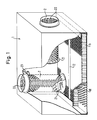
- Fig. 1 eine teilweise aufgeschnittene, räumliche Darstellung eines erfindungsgemäßen Lüftungskastens, bei dem zur Verdeutlichung die vertikale wie auch horizontale Anordnung eines Belüftungsrohres gezeigt ist,
- Fig. 2 einen Längsschnitt durch das Belüftungsrohr mit darin angeordneter Regelklappe, und
- Fig. 3 eine Teilansicht einer der Drehverbindungen von Regelklappe und Belüftungsrohr.
- Wie aus der Fig. 1 ersichtlich, besteht der erfindungsgemäße Lüftungskasten aus einem kastenförmigen Gehäuse 1 aus Stahlblech, das nach unten offen ist. Zwei parallel zueinanderliegende Seitenflächen des Gehäuses 1 sind im Bereich der Luftaustrittsöffnung rechtwinklig abgekantet, um als Auflage für ein die Luftaustrittsöffnung bedeckendes Lochblech 10 zu dienen. Das Lochblech 10 weist an zwei sich gegenüberliegenden Seitenflächen jeweils eine zweifache rechtwinklige Abkantung auf. In die U-förmigen Abkantungen ist ein Wabeneinsatz 11 eingeschoben, der nach Art einer Bienenwabe gestaltet ist, d.h. nebeneinander liegende Kanäle aufweist, die einen kreisrunden Querschnitt aufweisen. Der Wabeneinsatz 11 ist auf dem Lochblech 10 mittels eines Niederhalters 12, der zwischen dem Wabeneinsatz 11 und den U-förmigen Abkantungen des Lochbleches 10 eingeschoben ist, gehalten.
- Das kastenförmige Gehäuse 1 besitzt auf seiner Oberseite eine runde Öffnung, in die ein Belüftungsrohr 2 eingesetzt ist. Dieses Lüftungsrohr besteht - wie insbesondere aus Fig. 2 hervorgeht - aus einem die Mantelfläche des Belüftungsrohres 2 bildenden Lochblechzylinder, der bodenseitig, d.h. im Inneren des Gehäuses 1 mit einer Bodenplatte 21 verschlossen ist. Das Belüftungsrohr 2 besitzt auf seiner, der Blechscheibe 21 abgewandten, außerhalb des Lüftungskastens liegenden Seite einen Anschlußstutzen, der mit einer Zuluftquelle in Verbindung steht, die hier nicht gezeigt ist.
- Eine weitere Ausführungsform der Anordnung des Belüftungsrohres 2 im Gehäuse 1 mit horizontaler Belüftungsrohrachse ist auf der rechten Seite des Gehäuses 1 beispielhaft gezeigt.
- Wie in der Fig. 2 gezeigt, besitzt das Belüftungsrohr 2 eine Regelklappe 22, deren Außendurchmesser etwas kleiner ist als der des Lochblechzylinders des Belüftungsrohres 2 und die über zwei Lagerzapfen 26 im Lochblechzylinder um eine horizontale Achse schwenkbar gelagert ist. Die Regelklappe 22 besteht ebenfalls aus Lochblech und ist mittels eines Hebels 23 in ihrer Lage einstellbar.
- In der Fig. 3 ist einer der zwei Lagerzapfen der Regelklappe 22 in vergrößerter Darstellung gezeigt. Am Außenumfang der Regelklappe 22 ist ein U-förmiger Winkel 25 angebracht, in dessen Schenkeln Bohrungen zum Durchlaß des Lagerzapfens 26 eingebracht sind. Der Lagerzapfen 26 steckt in den Bohrungen im Winkel 25 sowie in einer der Öffnungen im Lochblechzylinder des Belüftungsrohrs 3 . Mittels einer Schraubenfeder 24 ist der Lagerzapfen im Winkel 25 gesichert. Die Feder 24 stützt sich dabei an einem ihrer Enden an einem der Schenkel des Winkels 25 ab und greift mit dem anderen Ende in eine im Lagerzapfen 26 eingebrachte Nut ein. Hierdurch ist die Lage des Lagerzapfens 26 gesichert. Außerdem kann ohne großen Aufwand die Regelklappe 22 entfernt werden, indem der Lagerzapfen 26 gegen die Federkraft der Feder 24 zurückgeschoben wird.
- Der erfindungsgemäße Lüftungskasten ist Bestandteil einer Lüftungsdecke, kann den Erfordernissen entsprechend in seiner Größe variiert werden und ein oder mehrere Belüftungsrohre 2 aufweisen. Die Belüftungsrohre 2 können entweder mit vertikaler Achse, wie in Fig. 1 links dargestellt, oder mit horizontaler Achse, wie in Fig. 1 rechts dargestellt, eingebaut werden. Verschiedene Versuche haben ergeben, daß die Wirkung im wesentlichen gleich ist und die Einbaulage der Belüftungsrohre 2 daher lediglich von den Raumverhältnissen abhängig ist. Ist über der Belüftungsdecke, in die der erfindungsgemäße Lüftungskasten integriert ist, genügend Raum vorhanden, so ist eine Einbaulage des Belüftungsrohres 2 mit vertikaler Achse vorzuziehen. Sind jedoch die Raumverhältnisse über der Oberseite des Lüftungskastens beengt, so ist ein Einbau mit horizontaler Achse des Belüftungsrohres 2 zu empfehlen.
- Der erfindungsgemäße Lüftungskasten mit perforiertem Belüftungsrohr 2, darin angeordneter, perforierter Regelklappe 22, Wabeneinsatz 11 und Lochblech 10 erbringt einen sehr gleichmäßigen Luftaustritt über die gesamte Lochblechfläche. Versuche haben gezeigt, daß diese Kombination deshalb so vorteilhaft ist, weil durch das perforierte Belüftungsrohr 2 mit geschlossenem Boden 21 die Zuluft gleichmäßig im Inneren des Gehäuses 1 verteilt wird, so daß überall im Gehäuse 1 ein konstanter Druck herrscht. Der Wabeneinsatz 11 wiederum hat eine Richtwirkung. Durch die Öffnungen im Wabeneinsatz 11 wird die Luft aus dem Inneren des Gehäuses 1 vertikal ausgerichtet und strömt in einem gleichmäßigen Luftschleier durch das Lochblech 10 hindurch in den zu belüftenden Raum ein.
Claims (13)
dadurch gekennzeichnet, daß
dadurch gekennzeichnet, daß
der Wabeneinsatz (11) kreisrunde oder vielekkige, dicht nebeneinanderliegende Kanäle aufweist.
dadurch gekennzeichnet, daß
der Wabeneinsatz (11) eine Höhe von 10 bis 20 mm aufweist.
dadurch gekennzeichnet, daß
die einzelnen Kanäle des Wabeneinsatzes (11) jeweils einen Durchmesser von 3 bis 8 mm aufweisen.
dadurch gekennzeichnet, daß
die einzelnen Kanäle des Wabeneinsatzes (11) jeweils einen Durchmesser von 4 mm und eine Höhe von 13 mm aufweisen.
dadurch gekennzeichnet, daß
das Belüftungsrohr (2) vertikal im Gehäuse (1) angeordnet ist.
dadurch gekennzeichnet, daß
das Belüftungsrohr (2) in dem Gehäuse (1) horizontal angeordnet ist.
dadurch gekennzeichnet, daß
die Regelklappe (22) über einen Hebel (23) einstellbar ist.
dadurch gekennzeichnet, daß
die perforierte Mantelfläche des Belüftungsrohres (2) sowie die perforierte Regelklappe (22) die gleiche Perforation aufweisen.
dadurch gekennzeichnet, daß
die perforierte Mantelfläche des Belüftungsrohres (2) sowie die perforierte Regelklappe (23) regelmäßig verteilte Öffnungen aufweisen, die einen Durchmesser von 4 mm bis 6 mm haben.
dadurch gekennzeichnet, daß
die Öffnungen einen Durchmesser von 5 mm haben.
dadurch gekennzeichnet, daß
die Kanäle des Wabeneinsatzes (11) einen Durchmesser aufweisen, der kleiner ist als der Durchmesser der Öffnungen im Lochblech (10).
dadurch gekennzeichnet, daß
die Öffnungen des Lochblechs (10) einen Durchmesser von 2 mm bis 4 mm, bevorzugtermaßen einen Durchmesser von 2 mm haben.
Applications Claiming Priority (2)
| Application Number | Priority Date | Filing Date | Title |
|---|---|---|---|
| DE4343718 | 1993-12-21 | ||
| DE4343718A DE4343718A1 (de) | 1993-12-21 | 1993-12-21 | Lüftungskasten |
Publications (2)
| Publication Number | Publication Date |
|---|---|
| EP0667496A1 true EP0667496A1 (de) | 1995-08-16 |
| EP0667496B1 EP0667496B1 (de) | 1998-06-10 |
Family
ID=6505698
Family Applications (1)
| Application Number | Title | Priority Date | Filing Date |
|---|---|---|---|
| EP94120238A Expired - Lifetime EP0667496B1 (de) | 1993-12-21 | 1994-12-20 | Lüftungskasten |
Country Status (5)
| Country | Link |
|---|---|
| EP (1) | EP0667496B1 (de) |
| AT (1) | ATE167276T1 (de) |
| DE (2) | DE4343718A1 (de) |
| ES (1) | ES2119954T3 (de) |
| IL (1) | IL112026A (de) |
Cited By (2)
| Publication number | Priority date | Publication date | Assignee | Title |
|---|---|---|---|---|
| EP1637815A1 (de) * | 2004-06-10 | 2006-03-22 | Lindab AB | Belüftungsvorrichtung |
| WO2007121855A1 (en) * | 2006-04-20 | 2007-11-01 | Airbus Deutschland Gmbh | Noise optimized air distributor |
Families Citing this family (2)
| Publication number | Priority date | Publication date | Assignee | Title |
|---|---|---|---|---|
| CH703924A1 (de) * | 2010-10-13 | 2012-04-13 | Trox Hesco Schweiz Ag | Ebenflächige Ausströmwand eines Luftdurchlasses. |
| JP2015505025A (ja) * | 2011-12-05 | 2015-02-16 | カイプ プロプライエタリー リミテッド | 空気ディフューザおよび空気循環システム |
Citations (6)
| Publication number | Priority date | Publication date | Assignee | Title |
|---|---|---|---|---|
| US2825500A (en) * | 1956-03-09 | 1958-03-04 | Wallace W Mclean | Ventilating apparatus |
| DE2126491A1 (de) * | 1970-06-24 | 1971-12-30 | Ar Ventilation Ab | Luftausströmungsvorrichtung |
| DE2254169A1 (de) * | 1971-11-01 | 1973-05-10 | Trance Co | Luftverteiler |
| DE2754699C2 (de) * | 1976-12-09 | 1988-12-29 | Leif Ingemar Johanneshov Se Lind | |
| DE3805873A1 (de) * | 1988-02-25 | 1989-09-07 | Zander Waermetechnik Kulmbach | Luftauslasssystem in elementbauweise |
| DE4210807A1 (de) * | 1992-04-01 | 1993-10-07 | Siegle & Epple | Luftdurchlaß |
-
1993
- 1993-12-21 DE DE4343718A patent/DE4343718A1/de not_active Withdrawn
-
1994
- 1994-12-19 IL IL11202694A patent/IL112026A/en not_active IP Right Cessation
- 1994-12-20 DE DE59406209T patent/DE59406209D1/de not_active Expired - Lifetime
- 1994-12-20 EP EP94120238A patent/EP0667496B1/de not_active Expired - Lifetime
- 1994-12-20 AT AT94120238T patent/ATE167276T1/de active
- 1994-12-20 ES ES94120238T patent/ES2119954T3/es not_active Expired - Lifetime
Patent Citations (6)
| Publication number | Priority date | Publication date | Assignee | Title |
|---|---|---|---|---|
| US2825500A (en) * | 1956-03-09 | 1958-03-04 | Wallace W Mclean | Ventilating apparatus |
| DE2126491A1 (de) * | 1970-06-24 | 1971-12-30 | Ar Ventilation Ab | Luftausströmungsvorrichtung |
| DE2254169A1 (de) * | 1971-11-01 | 1973-05-10 | Trance Co | Luftverteiler |
| DE2754699C2 (de) * | 1976-12-09 | 1988-12-29 | Leif Ingemar Johanneshov Se Lind | |
| DE3805873A1 (de) * | 1988-02-25 | 1989-09-07 | Zander Waermetechnik Kulmbach | Luftauslasssystem in elementbauweise |
| DE4210807A1 (de) * | 1992-04-01 | 1993-10-07 | Siegle & Epple | Luftdurchlaß |
Cited By (4)
| Publication number | Priority date | Publication date | Assignee | Title |
|---|---|---|---|---|
| EP1637815A1 (de) * | 2004-06-10 | 2006-03-22 | Lindab AB | Belüftungsvorrichtung |
| WO2007121855A1 (en) * | 2006-04-20 | 2007-11-01 | Airbus Deutschland Gmbh | Noise optimized air distributor |
| JP2009534621A (ja) * | 2006-04-20 | 2009-09-24 | エアバス・オペレーションズ・ゲーエムベーハー | 雑音最適化した空気分配器 |
| US7815012B2 (en) | 2006-04-20 | 2010-10-19 | Airbus Deutschland Gmbh | Noise optimized air distributor |
Also Published As
| Publication number | Publication date |
|---|---|
| ES2119954T3 (es) | 1998-10-16 |
| EP0667496B1 (de) | 1998-06-10 |
| DE4343718A1 (de) | 1995-06-22 |
| DE59406209D1 (de) | 1998-07-16 |
| IL112026A (en) | 1996-12-05 |
| ATE167276T1 (de) | 1998-06-15 |
| IL112026A0 (en) | 1995-03-15 |
Similar Documents
| Publication | Publication Date | Title |
|---|---|---|
| DE2754699C2 (de) | ||
| DE202008018286U1 (de) | Luftauslass | |
| DE1289284B (de) | ||
| DE2609030C3 (de) | Vorrichtung zum Führen von aus einer luftdurchlässigen perforierten Fläche austretenden Luftströmen | |
| DE1271951B (de) | Luft-Diffusor | |
| DE2518609A1 (de) | Kombinations-schlitzauslass mit auswechselbarem filter fuer lueftungsund klimaanlagen | |
| EP0667496B1 (de) | Lüftungskasten | |
| DE3805873A1 (de) | Luftauslasssystem in elementbauweise | |
| DE3410078A1 (de) | Deckenluftauslass fuer hohe raeume | |
| EP4232758A1 (de) | Verschlusseinheit einer lüftungsvorrichtung | |
| DE69100459T2 (de) | Endauslass für Raumlüftungsanlagen. | |
| DE102013111244A1 (de) | Luftauslass | |
| DE8713209U1 (de) | Deckenluftauslaß | |
| DE19626884A1 (de) | Luftauslaß | |
| CH652195A5 (en) | Device for controlling the airflow arriving from an air-preparation installation on distribution to individual rooms | |
| DE69105947T2 (de) | Lüftungsanlage. | |
| EP3587943A2 (de) | Vorrichtung zur belüftung und temperierung eines raums eines gebäudes | |
| DE2401801A1 (de) | Luftverteilervorrichtung | |
| DE3529013A1 (de) | Luftauslasskopf fuer anlagen zur klimatisierung oder belueftung von raeumen | |
| DE1105587B (de) | Luftkanal fuer Lueftungsanlagen | |
| DE69400879T2 (de) | Selbstregelnder Lüftungsrost | |
| EP1471313A1 (de) | Gehäuse für die Luftdurchführung | |
| DE1454656A1 (de) | Deckenkonstruktion | |
| DE2810383C2 (de) | Ausblaseeinheit mit Regulierung bzw. Verschiebung der auszublasenden Luftmenge | |
| DE2735643A1 (de) | Luftauslass fuer die klimatisierung von aufenthaltsraeumen |
Legal Events
| Date | Code | Title | Description |
|---|---|---|---|
| PUAI | Public reference made under article 153(3) epc to a published international application that has entered the european phase |
Free format text: ORIGINAL CODE: 0009012 |
|
| AK | Designated contracting states |
Kind code of ref document: A1 Designated state(s): AT BE CH DE DK ES FR GB GR IE IT LI LU MC NL PT SE |
|
| 17P | Request for examination filed |
Effective date: 19950922 |
|
| GRAG | Despatch of communication of intention to grant |
Free format text: ORIGINAL CODE: EPIDOS AGRA |
|
| 17Q | First examination report despatched |
Effective date: 19970725 |
|
| GRAG | Despatch of communication of intention to grant |
Free format text: ORIGINAL CODE: EPIDOS AGRA |
|
| GRAH | Despatch of communication of intention to grant a patent |
Free format text: ORIGINAL CODE: EPIDOS IGRA |
|
| GRAH | Despatch of communication of intention to grant a patent |
Free format text: ORIGINAL CODE: EPIDOS IGRA |
|
| GRAA | (expected) grant |
Free format text: ORIGINAL CODE: 0009210 |
|
| AK | Designated contracting states |
Kind code of ref document: B1 Designated state(s): AT BE CH DE DK ES FR GB GR IE IT LI LU MC NL PT SE |
|
| PG25 | Lapsed in a contracting state [announced via postgrant information from national office to epo] |
Ref country code: GR Free format text: LAPSE BECAUSE OF NON-PAYMENT OF DUE FEES Effective date: 19980610 |
|
| REF | Corresponds to: |
Ref document number: 167276 Country of ref document: AT Date of ref document: 19980615 Kind code of ref document: T |
|
| REG | Reference to a national code |
Ref country code: CH Ref legal event code: NV Representative=s name: BUECHEL & PARTNER AG PATENTBUERO Ref country code: CH Ref legal event code: EP |
|
| GBT | Gb: translation of ep patent filed (gb section 77(6)(a)/1977) |
Effective date: 19980611 |
|
| REF | Corresponds to: |
Ref document number: 59406209 Country of ref document: DE Date of ref document: 19980716 |
|
| ITF | It: translation for a ep patent filed | ||
| PG25 | Lapsed in a contracting state [announced via postgrant information from national office to epo] |
Ref country code: SE Free format text: LAPSE BECAUSE OF FAILURE TO SUBMIT A TRANSLATION OF THE DESCRIPTION OR TO PAY THE FEE WITHIN THE PRESCRIBED TIME-LIMIT Effective date: 19980910 Ref country code: DK Free format text: LAPSE BECAUSE OF FAILURE TO SUBMIT A TRANSLATION OF THE DESCRIPTION OR TO PAY THE FEE WITHIN THE PRESCRIBED TIME-LIMIT Effective date: 19980910 |
|
| ET | Fr: translation filed | ||
| PG25 | Lapsed in a contracting state [announced via postgrant information from national office to epo] |
Ref country code: PT Free format text: LAPSE BECAUSE OF FAILURE TO SUBMIT A TRANSLATION OF THE DESCRIPTION OR TO PAY THE FEE WITHIN THE PRESCRIBED TIME-LIMIT Effective date: 19980915 |
|
| REG | Reference to a national code |
Ref country code: IE Ref legal event code: FG4D Free format text: GERMAN |
|
| REG | Reference to a national code |
Ref country code: ES Ref legal event code: FG2A Ref document number: 2119954 Country of ref document: ES Kind code of ref document: T3 |
|
| PGFP | Annual fee paid to national office [announced via postgrant information from national office to epo] |
Ref country code: BE Payment date: 19981216 Year of fee payment: 5 |
|
| PG25 | Lapsed in a contracting state [announced via postgrant information from national office to epo] |
Ref country code: LU Free format text: LAPSE BECAUSE OF NON-PAYMENT OF DUE FEES Effective date: 19981220 |
|
| PG25 | Lapsed in a contracting state [announced via postgrant information from national office to epo] |
Ref country code: IE Free format text: LAPSE BECAUSE OF NON-PAYMENT OF DUE FEES Effective date: 19990219 |
|
| REG | Reference to a national code |
Ref country code: IE Ref legal event code: FD4D |
|
| PLBE | No opposition filed within time limit |
Free format text: ORIGINAL CODE: 0009261 |
|
| STAA | Information on the status of an ep patent application or granted ep patent |
Free format text: STATUS: NO OPPOSITION FILED WITHIN TIME LIMIT |
|
| 26N | No opposition filed | ||
| PG25 | Lapsed in a contracting state [announced via postgrant information from national office to epo] |
Ref country code: MC Free format text: LAPSE BECAUSE OF NON-PAYMENT OF DUE FEES Effective date: 19990630 |
|
| PG25 | Lapsed in a contracting state [announced via postgrant information from national office to epo] |
Ref country code: NL Free format text: LAPSE BECAUSE OF NON-PAYMENT OF DUE FEES Effective date: 19990701 |
|
| NLV4 | Nl: lapsed or anulled due to non-payment of the annual fee |
Effective date: 19990701 |
|
| PG25 | Lapsed in a contracting state [announced via postgrant information from national office to epo] |
Ref country code: BE Free format text: LAPSE BECAUSE OF NON-PAYMENT OF DUE FEES Effective date: 19991231 |
|
| BERE | Be: lapsed |
Owner name: WIMBOCK BESITZ G.M.B.H. Effective date: 19991231 |
|
| REG | Reference to a national code |
Ref country code: GB Ref legal event code: IF02 |
|
| PGFP | Annual fee paid to national office [announced via postgrant information from national office to epo] |
Ref country code: ES Payment date: 20031210 Year of fee payment: 10 |
|
| PG25 | Lapsed in a contracting state [announced via postgrant information from national office to epo] |
Ref country code: ES Free format text: LAPSE BECAUSE OF NON-PAYMENT OF DUE FEES Effective date: 20041221 |
|
| REG | Reference to a national code |
Ref country code: ES Ref legal event code: FD2A Effective date: 20041221 |
|
| PGFP | Annual fee paid to national office [announced via postgrant information from national office to epo] |
Ref country code: CH Payment date: 20080129 Year of fee payment: 14 |
|
| PGFP | Annual fee paid to national office [announced via postgrant information from national office to epo] |
Ref country code: IT Payment date: 20080130 Year of fee payment: 14 |
|
| REG | Reference to a national code |
Ref country code: GB Ref legal event code: 732E Free format text: REGISTERED BETWEEN 20090604 AND 20090610 |
|
| REG | Reference to a national code |
Ref country code: CH Ref legal event code: PL |
|
| PG25 | Lapsed in a contracting state [announced via postgrant information from national office to epo] |
Ref country code: LI Free format text: LAPSE BECAUSE OF NON-PAYMENT OF DUE FEES Effective date: 20081231 Ref country code: CH Free format text: LAPSE BECAUSE OF NON-PAYMENT OF DUE FEES Effective date: 20081231 |
|
| REG | Reference to a national code |
Ref country code: FR Ref legal event code: TP |
|
| REG | Reference to a national code |
Ref country code: FR Ref legal event code: CA |
|
| PG25 | Lapsed in a contracting state [announced via postgrant information from national office to epo] |
Ref country code: IT Free format text: LAPSE BECAUSE OF NON-PAYMENT OF DUE FEES Effective date: 20081220 |
|
| PGFP | Annual fee paid to national office [announced via postgrant information from national office to epo] |
Ref country code: GB Payment date: 20131227 Year of fee payment: 20 Ref country code: AT Payment date: 20131204 Year of fee payment: 20 Ref country code: DE Payment date: 20131230 Year of fee payment: 20 |
|
| PGFP | Annual fee paid to national office [announced via postgrant information from national office to epo] |
Ref country code: FR Payment date: 20131217 Year of fee payment: 20 |
|
| REG | Reference to a national code |
Ref country code: DE Ref legal event code: R071 Ref document number: 59406209 Country of ref document: DE |
|
| REG | Reference to a national code |
Ref country code: DE Ref legal event code: R071 Ref document number: 59406209 Country of ref document: DE |
|
| REG | Reference to a national code |
Ref country code: GB Ref legal event code: PE20 Expiry date: 20141219 |
|
| PG25 | Lapsed in a contracting state [announced via postgrant information from national office to epo] |
Ref country code: GB Free format text: LAPSE BECAUSE OF EXPIRATION OF PROTECTION Effective date: 20141219 |
|
| REG | Reference to a national code |
Ref country code: AT Ref legal event code: MK07 Ref document number: 167276 Country of ref document: AT Kind code of ref document: T Effective date: 20141220 |