EP0667720A2 - Appareil d'enregistrement et de reproduction de signaux vidéo - Google Patents
Appareil d'enregistrement et de reproduction de signaux vidéo Download PDFInfo
- Publication number
- EP0667720A2 EP0667720A2 EP95300889A EP95300889A EP0667720A2 EP 0667720 A2 EP0667720 A2 EP 0667720A2 EP 95300889 A EP95300889 A EP 95300889A EP 95300889 A EP95300889 A EP 95300889A EP 0667720 A2 EP0667720 A2 EP 0667720A2
- Authority
- EP
- European Patent Office
- Prior art keywords
- signals
- accompanying
- video
- blocks
- copy protection
- Prior art date
- Legal status (The legal status is an assumption and is not a legal conclusion. Google has not performed a legal analysis and makes no representation as to the accuracy of the status listed.)
- Granted
Links
Images








Classifications
-
- H—ELECTRICITY
- H04—ELECTRIC COMMUNICATION TECHNIQUE
- H04N—PICTORIAL COMMUNICATION, e.g. TELEVISION
- H04N9/00—Details of colour television systems
- H04N9/79—Processing of colour television signals in connection with recording
- H04N9/80—Transformation of the television signal for recording, e.g. modulation, frequency changing; Inverse transformation for playback
- H04N9/82—Transformation of the television signal for recording, e.g. modulation, frequency changing; Inverse transformation for playback the individual colour picture signal components being recorded simultaneously only
- H04N9/8205—Transformation of the television signal for recording, e.g. modulation, frequency changing; Inverse transformation for playback the individual colour picture signal components being recorded simultaneously only involving the multiplexing of an additional signal and the colour video signal
-
- H—ELECTRICITY
- H04—ELECTRIC COMMUNICATION TECHNIQUE
- H04N—PICTORIAL COMMUNICATION, e.g. TELEVISION
- H04N5/00—Details of television systems
- H04N5/76—Television signal recording
- H04N5/91—Television signal processing therefor
- H04N5/913—Television signal processing therefor for scrambling ; for copy protection
-
- H—ELECTRICITY
- H04—ELECTRIC COMMUNICATION TECHNIQUE
- H04N—PICTORIAL COMMUNICATION, e.g. TELEVISION
- H04N9/00—Details of colour television systems
- H04N9/79—Processing of colour television signals in connection with recording
- H04N9/80—Transformation of the television signal for recording, e.g. modulation, frequency changing; Inverse transformation for playback
- H04N9/804—Transformation of the television signal for recording, e.g. modulation, frequency changing; Inverse transformation for playback involving pulse code modulation of the colour picture signal components
- H04N9/8042—Transformation of the television signal for recording, e.g. modulation, frequency changing; Inverse transformation for playback involving pulse code modulation of the colour picture signal components involving data reduction
- H04N9/8047—Transformation of the television signal for recording, e.g. modulation, frequency changing; Inverse transformation for playback involving pulse code modulation of the colour picture signal components involving data reduction using transform coding
-
- H—ELECTRICITY
- H04—ELECTRIC COMMUNICATION TECHNIQUE
- H04N—PICTORIAL COMMUNICATION, e.g. TELEVISION
- H04N5/00—Details of television systems
- H04N5/76—Television signal recording
- H04N5/91—Television signal processing therefor
- H04N5/913—Television signal processing therefor for scrambling ; for copy protection
- H04N2005/91307—Television signal processing therefor for scrambling ; for copy protection by adding a copy protection signal to the video signal
- H04N2005/91321—Television signal processing therefor for scrambling ; for copy protection by adding a copy protection signal to the video signal the copy protection signal being a copy protection control signal, e.g. a record inhibit signal
-
- H—ELECTRICITY
- H04—ELECTRIC COMMUNICATION TECHNIQUE
- H04N—PICTORIAL COMMUNICATION, e.g. TELEVISION
- H04N5/00—Details of television systems
- H04N5/76—Television signal recording
- H04N5/91—Television signal processing therefor
- H04N5/913—Television signal processing therefor for scrambling ; for copy protection
- H04N2005/91307—Television signal processing therefor for scrambling ; for copy protection by adding a copy protection signal to the video signal
- H04N2005/91328—Television signal processing therefor for scrambling ; for copy protection by adding a copy protection signal to the video signal the copy protection signal being a copy management signal, e.g. a copy generation management signal [CGMS]
-
- H—ELECTRICITY
- H04—ELECTRIC COMMUNICATION TECHNIQUE
- H04N—PICTORIAL COMMUNICATION, e.g. TELEVISION
- H04N9/00—Details of colour television systems
- H04N9/79—Processing of colour television signals in connection with recording
- H04N9/80—Transformation of the television signal for recording, e.g. modulation, frequency changing; Inverse transformation for playback
- H04N9/804—Transformation of the television signal for recording, e.g. modulation, frequency changing; Inverse transformation for playback involving pulse code modulation of the colour picture signal components
- H04N9/806—Transformation of the television signal for recording, e.g. modulation, frequency changing; Inverse transformation for playback involving pulse code modulation of the colour picture signal components with processing of the sound signal
- H04N9/8063—Transformation of the television signal for recording, e.g. modulation, frequency changing; Inverse transformation for playback involving pulse code modulation of the colour picture signal components with processing of the sound signal using time division multiplex of the PCM audio and PCM video signals
Definitions
- FIG. 1 is a block diagram of a proposed signal processing circuit of the recording side of a digital recording and reproducing device and is described in copending application serial no. (attorney docket 450100-3160).
- an analog composite video signal which, for example, is comprised of video signals Y, R-Y, and B-Y, is supplied to an A/D processing circuit 1, which converts the analog composite video signal to a digital video signal and delivers the signal to a blocking/shuffling circuit 2.
- the blocking/shuffling circuit 2 samples the data in an effective scan area of one frame of the digital composite video signal (that is, an area which contains viewable information) and arranges the samples into units.
- the Y, R-Y, and B-Y components of the digital composite video signal of the frame are respectively divided into a predetermined number of horizontal samples and into a predetermined number of vertical samples, and the samples are grouped into units formed of eight horizontal samples by eight vertical samples.
- the blocking/shuffling circuit 2 supplies the units to a Discrete Cosine Transform (DCT) circuit 3 which transforms the units into DCT units and delivers the DCT units to encoding circuit 4.
- the encoding circuit 4 quantizes the DCT units and variable length encodes the quantized DCT units using, for example, a two-dimensional Huffman code.
- the encoding circuit 4 quantizes the DCT units in buffering units of 30 DCT units each, for example, so that the length of the variable length encoded output of the encoding circuit 4 is within a predefined value.
- DCT Discrete Cosine Transform
- An input analog audio signal is converted to a digital audio signal by an A/D processing circuit 7 which delivers the digital audio signal to an interleaving circuit 8.
- the interleaving circuit 8 interleaves the digital audio signal so that the effect of burst errors on the sound quality is minimized and then delivers the interleaved audio signal to the switching circuit 6.
- a microprocessor 10 generates and delivers accompanying audio and video information to an accompanying (AUX) data generating circuit 11 which forms blocks of accompanying video signals, such as formatted VAUX signals, and blocks of accompanying audio signals, such as formatted AAUX signals, under the control of the microprocessor 10.
- VAUX and AAUX signals are described in application (attorney docket 450100-3160).
- the AUX data generating circuit 11 delivers the formatted VAUX signals and the formatted AAUX signals to the switching circuit 6.
- the microprocessor 10 generates and delivers subcode information, used for high-speed searching of the recording medium, to a subcode generating circuit 13 which generates formatted subcode signals under the control of the microprocessor 10.
- the subcode generating circuit 13 delivers the formatted subcode signals to the switching circuit 6.
- the deshuffling circuit 14 temporarily stores the blocks of associated video signals, the blocks of associated audio signals and the formatted subcode signals in frame memory and rearranges the blocks of associated video signals so that blocks of associated video signals that correspond to adjacent regions of the video frame are recorded on adjacent regions of the recording medium.
- the deshuffling circuit 14 delivers the rearranged blocks of associated video signals, the block of associated audio signals and the formatted subcode signals to a parity generating circuit 15 which adds an error correcting code and delivers the signals to a channel encoder 16.
- the channel encoder 16 signal modulates the rearranged blocks of associated video signals, the blocks of associated audio signals and the formatted subcode signals by affixing a SYNC signal to the signals, for example, and converts the signals to serial form.
- the channel encoder 16 supplies the signals to a recording head for recording onto a recording medium.
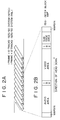
- Fig. 2 shows a recording format for the signals formed by the processing circuit shown in Fig. 1.
- a plurality of helically recorded tracks form one picture frame, as shown in Fig. 2A.
- a frame is recorded in ten tracks
- a frame is recorded in 12 tracks.
- Fig. 2B shows the recording format for one track of the frame.
- the track is bounded by margins, and starting from the left most margin, which represents the recording start end, there are recorded an audio area, a video area and a subcode area. Inter-block gaps, which serve as a margin for editing and for prevention of overwriting of data, are provided between these areas.
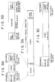
- Fig. 3 shows the respective areas of one track in greater detail.
- the audio area shown in Fig. 3B, is comprised of a pre-amble sector, which includes a run-up block and a pre-sync block, an audio sector and a post-amble sector, which includes post-sync and guard area blocks.
- the pre- and post-sync blocks include a 2 byte sync region formed by a recording signal modulating circuit (not shown) using 24 to 25 conversion, and a 3 byte ID region formed by an ID data adding circuit (not shown).
- the video area shown in Fig. 3C, includes a pre-amble sector, which includes run-up and pre-sync regions, a video sector, and a post-amble sector, which includes post-sync and guard area regions.
- the video sector is divided into sync blocks and each sync block includes 2 bytes of sync data and 3 bytes of ID data, shown in Fig. 6.
- the pre-sync blocks and the post-sync block are structured in a manner similar to the pre- and post-sync blocks of the audio sector.
- the video sector of the video area is shown in detail in Fig. 6 and includes 149 sync blocks.
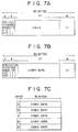
- Sync blocks ⁇ , ⁇ and ⁇ shown in greater detail in Fig. 7A, are VAUX sync blocks and store the accompanying video information signals.
- the 135 remaining sync blocks, shown in Fig. 6, include video data as well as inner parity data and form buffering units BUF0 to BUF26.
- the eleven sync blocks C2 are parity sync blocks and include both outer parity data and inner parity data.
- Fig. 7C illustrates a buffering unit formed of five sync blocks, each comprised of the 77 bytes of video data shown in Fig 7B.
- the first byte is a Q data byte in which quantization data is stored.
- Following the Q byte are 76 bytes of video signal data.
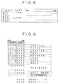
- the AAUX region of the audio sector of the audio area shown in Fig. 5B and the VAUX region of the video sector of the video area shown in Fig. 7A are each formed of "packs", shown in Fig. 8.
- the first byte PC0 of the pack serves as a pack header (ITEM) and the remaining bytes, PC1-PC4, serve as pack data.
- the ITEM data is divided into upper 4-bit data and lower 4-bit data.
- the upper 4-bit data identifies what is referred to as a "large” item, and the lower 4-bit data identifies what is referred to as a "small” item.
- the upper 4-bit "large” item and the lower 4-bit “small” item define the format and content of the succeeding data. There are at most 16 “large” items, and for a respective "large” item, there are at most 16 "small” items.
- the large items identified by the upper 4 bits of the item data include, as shown in Fig. 9, control [0000], title [0001], chapter [0010], part [0011], and program [0100] items.
- Line item [0101] indicates data recorded during a vertical blanking period.
- Other items include the video auxiliary (VAUX) data [0110], the audio auxiliary (AAUX) data [0111] and soft mode data [1111], which is designated for software applications.
- Large items [1000] to [1110] are reserved items for future applications.
- Each VAUX sync block includes 15 5-byte packs, for a total of 45 packs per track. Similarly, nine 5-byte packs are recorded in the AAUX regions of the audio sector shown in Fig. 5A.
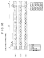
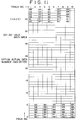
- Fig. 11 shows the VAUX pack data structure of one frame.
- an NTSC frame consisting of 10 tracks, there is a total of 450 VAUX regions, 45 per track. Of the 45 VAUX regions in each track, 6 are designated as main VAUX regions, numbered 60-65, and the remaining are designated as optional regions.
- main VAUX regions there are recorded packs of information regarding basic data common to all tapes.
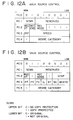
- VAUX packs formed by the VAUX large item [0110] and its respective small items include the VAUX SOURCE pack [0110 0000] (the hexadecimal representation of which is “60”), the VAUX SOURCE CONTROL pack [0110 0001] ("61"), the VAUX REC DATA pack [0110 0010] ("62"), the VAUX REC TIME pack [0110 0011] ("63") and the VAUX REC TIME BINARY GROUP pack [0110 0100] ("64”).
- the VAUX SOURCE CONTROL pack [0110 0001] ("61") includes a Serial Copy Management System (SCMS) code which includes copy protection information for restricting the number of times the video signals are to be copied.
- SCMS Serial Copy Management System
- the upper ("copy protect") bit of the SCMS code indicates whether copying of the video signals is permitted and has a value "0" when copying is permitted and value "1" when copying is not permitted.
- the value of the lower (“original") bit of the SCMS code indicates whether the video signals stored in the recording medium is the original copy ("0") or not ("1").
- the VAUX SOURCE CONTROL pack also includes flag code "REC ST” which indicates whether or not a recording signal is the starting point for recording.
- REC MODE indicates whether a recorded item is an original or an after-recorded item.
- FF is a flag which indicates whether or not the video signal is a 1-field signal that is repeated to form a frame.
- Flag "FS” indicates whether or not the record is an odd-order field, and flag "FC” indicates whether or not the video data in a present frame is identical to the video data in the immediately preceding frame.
- Flag "IL” indicates whether or not the recording signal is interlaced.
- ST is a flag which indicates whether or not the recording signal is a still picture signal
- SC is a flag which indicates whether or not the image content to be recorded is a still picture that is reproduced with the tape travel of the reproducing VTR temporarily stopped.
- BCSYS represents the aspect ratio.
- GENE CATEGORY is a code which represents the genre of a recorded item.
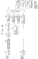
- Fig. 14 is a block diagram of a reproducing side of a digital recording and reproducing device of the type described in the aforenoted application.
- signals reproduced from the recording medium by a reproducing head (not shown) are supplied to a channel decoder 25 which converts the signals from series to parallel form and then demodulates them.
- the channel decoder 25 delivers the demodulated signals to an error correcting circuit 27 via a time base correcting circuit (TBC) 26.
- TBC time base correcting circuit
- the error correcting circuit 27 error corrects the signals or, if too many errors are present in a portion of the signals, appends an error flag to that portion.
- the shuffling circuit 28 supplies the shuffled signals to a switching circuit 6, comprised of a demultiplexing circuit or, preferably, a multiplexing/demultiplexing circuit, which separates the signals into signals representing the above-described video, audio and subcode areas, divides the video area signals into blocks of video signals and into blocks of VAUX signals and divides the audio area signals into blocks of audio signals and blocks of AAUX signals.
- the blocks of VAUX signals and the blocks of AAUX signals are formed of, for example, the packs shown in Fig. 8.
- the switching circuit 6 supplies the blocks of video signals to a deframing circuit 29 which decomposes the blocks of video signals into variable length encoded video signals which are then supplied to a decoding circuit 30.
- the decoding circuit 30 variable length decodes and inverse quantizes the variable length encoded video signals and then supplies the decoded and dequantized signals to an inverse DCT (IDCT) circuit 31 which decompresses and supplies the decompressed video signals to a de-blocking/de-shuffling circuit 32.
- IDCT inverse DCT
- the de-brocking/de-shuffling circuit 32 supplies the de-shuffled video signal to a D/A conversion circuit 33 which converts the de-shuffled video signal to an analog composite video signal which is comprised of, for example, a Y signal, a R-Y signal, and a B-Y signal.
- the analog video signal is supplied to an output terminal and, as an example, is delivered to a display device where a reproduced image is displayed.
- the switching circuit 6 supplies the blocks of audio signals to a de-interleaving circuit 34 which operates in a complementary manner to interleave circuit 8 of Fig. 1 and further processes the audio signals which then are supplied to D/A conversion circuit 35 for output as an analog audio signal.
- the switching circuit 6 also supplies the blocks of VAUX and AAUX signals to an AUX data decoder 24 which decodes the accompanying audio and video information and supplies the decoded information to microprocessor 10 which performs various controlling operations as a function of the accompanying audio and video information.
- the switching circuit 6 further supplies the subcode signals to a subcode data decoder 36 which decodes information from the subcode data and supplies the decoded information to the microprocessor 10.
- Fig. 15 is a block diagram of a signal processing circuit of the reproducing side of a digital recording and reproducing device of the type described in copending application Serial No. (attorney docket 450100-3160) which includes the circuit shown in Fig. 14.
- the signal processing circuit processes signals reproduced from the recording medium for output as analog audio and video signals and also is adapted to transmit the reproduced signals over a digital transmission line via a digital interface.
- those components which are the same as those shown in Fig. 14 are identified by the same reference numerals and further description thereof is omitted.
- the shuffling circuit 28 of Fig. 15 shuffles signals derived from the reproduced signals, as described above with reference to Fig. 14, and supplies the shuffled signals to a packetizing circuit 17 which arranges the shuffled signals into packets of predetermined size.
- the packets are delivered to a parity generator circuit 18 which adds parity data that is used at the remote end of the digital transmission line for detecting communication errors.
- the parity generator 18 supplies the packets and the parity data to a driver circuit 19 which channel codes the packets and the parity data into signals that are suitable for transmission over the digital transmission line, which may be, for example, twisted pair cable, and then serially transmits the signals over the digital transmission line via the digital interface.
- Fig. 16 is a block diagram of the recording side of a known digital recording and reproducing device of the type described in the aforementioned application and which includes the circuit shown in Fig. 1 herein and in which the signals transmitted by the circuit shown in Fig. 15, for example, are received and processed for recording onto a recording medium.
- the apparatus shown in Fig. 16 may be connected to the remote end of the digital transmission line mentioned in connection with the signal processing circuit of Fig. 15.
- those components which are the same as those shown in Fig. 1 are identified by the same reference numerals and further description thereof is omitted.
- the signals transmitted by the signal processing circuit of Fig. 15 over the digital transmission line are received via a digital interface and supplied to a receiver circuit 21 which converts the serially transmitted signals to parallel encoded signals and then channel-decodes the signals to recover the packets.
- the receiver circuit 21 delivers the decoded packets to an error detecting circuit 22 which determines whether an error is present in the packets and, when an error is detected, appends an error flag to the packet.
- the detecting circuit 22 supplies the packets to a depacketizing circuit 23 which arranges the packets into blocks of associated video signals, blocks of associated audio signals and formatted subcode signals and delivers the signals to the switching circuit 6.
- the switching circuit 6 separates the blocks of associated video signals into blocks of video signals and into blocks of VAUX signals and separates the blocks of associated audio signals into blocks of audio signals and blocks of AAUX signals for further processing by deshuffling circuit 14, parity generator 15 and channel encoder 16, for example, for subsequent recording onto a recording medium.
- the blocks of VAUX signals and the blocks of AAUX signals are formed of, for example, the packs shown in Fig. 8.
- the switching circuit 6 also supplies the blocks of VAUX and AAUX signals to the AUX data decoder 24 which decodes accompanying audio and video information from the blocks of AAUX and VAUX signals and supplies the decoded accompanying audio and video information to the microprocessor 10 which performs various controlling operations.
- the microprocessor 10 delivers accompanying audio and video information to the AUX data generating circuit 11 for further processing as described above with reference to Fig. 1.
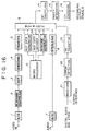
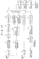
- Fig. 17 is a block diagram of the recording side of a digital recording and reproducing device of the type described in the aforementioned application in which analog composite video signals are received and processed for digital recording onto the recording medium as well as for transmission over a digital transmission line.
- the analog composite video signals include video information and copy protection information, the latter being disposed in the vertical blanking period of the video signal for restricting the number of times the video information may be copied.
- Fig. 17 includes the circuit shown Fig. 1 as well as the circuit shown in Fig. 15 which is used to transmit digital video signals over the digital transmission line and those components which have been described previously are identified by the same reference numerals.
- the input analog composite video signal is supplied to the A/D processing circuit 1 for further processing as described above with reference to Fig. 1.
- the analog composite video signal is also supplied to a vertical blanking (VBLK) signal decoder circuit 9 which decodes the copy protection information present in the vertical blanking period of the analog video signal and delivers the copy protection information to the microprocessor 10.
- VBLK vertical blanking
- the microprocessor determines whether copying of the video information is permitted based on the copy protection information and, if copying is permitted, generates SCMS code comprising updated copy protection information that indicates that the video information was copied.
- the microprocessor 10 delivers the SCMS code to the AUX data generating circuit 11 which generates blocks of accompanying audio and video signals which include, for example, the packs of VAUX and AAUX signals shown in Figs. 12(1)-12(2) and having the SCMS code.
- the AUX data generating circuit 11 supplies the blocks of accompanying audio and video signals to the switching circuit 6 which combines the blocks of audio signals and the blocks of accompanying audio signals to form the blocks of associated audio signals and combines the blocks of video signals and the blocks of accompanying video signals to form the blocks of associated video signals which are delivered to the deshuffling circuit 14 and further processed, as described above with reference to Fig. 1, for recording in a digital recording medium.
- the blocks of associated video signals, the blocks of associated audio signals and the formatted subcode signals are also supplied by the switching circuit 6 to the packetizing circuit 17 and further processed, as described above with reference to Fig. 15, for transmission over the digital transmission line via the digital interface.
- Fig. 18A-18C illustrate various arrangements for dubbing a recording of, for example, video and audio information, stored on an original recording medium, such as a tape, onto one or more copy media using, for example, the recording and reproducing devices shown in Figs. 1 and 14-17.
- the recording includes copy protection information for restricting the number of times that the recording may be copied, or dubbed.
- Fig. 18A illustrates dubbing an original recording in which the copy protection information included therein permits the original recording to be copied.
- the original recording stored on a tape 40 is reproduced by a reproducing circuit 41, such as is shown Figs. 14 or 15, and is outputted as analog audio and video signals to a recording circuit 42, such as the type shown in Fig. 17.
- a reproducing circuit 41 such as is shown Figs. 14 or 15
- a recording circuit 42 such as the type shown in Fig. 17.
- the reproduced recording is further processed for recording onto a copy recording medium 43.
- the reproduced recording may be outputted as digital audio and video signals via a digital transmission line from reproducing circuit 41 to the recording circuit 42 for further processing and recording onto the copy recording medium 43.
- Fig. 18B illustrates the attempted dubbing of an original recording in which the copy protection information included therein does not permit copying of the original recording.
- the original recording stored on a tape 45 is reproduced by a reproducing circuit 46 and because copying is not permitted, the reproduced recording is not outputted to a recording circuit 47.
- the reproduced recording is outputted by the reproducing circuit 46 to the recording circuit 47, which may be of the type shown in Fig. 17, but because copying is not permitted, the recording circuit 47 does not record the reproduced recording supplied thereto onto a copy recording medium 48.
- FIG. 18C illustrates the attempted concurrent dubbing of an original recording onto first and second copy recording media and in which the copy protection information included in the original recording on tape 50 permits copying from the original recording but does not permit copying from a copy of that original recording.
- the original recording stored on tape 50 is reproduced by a reproducing circuit 51 and because copying of the original recording is permitted, the original recording is outputted to a recording and transmission circuit 52.
- Circuit 52 generates updated copy protection information that indicates that the video information was copied once and cannot be further copied, and this updated copy protection information is recorded with the reproduced recording onto a copy recording medium 53.
- Circuit 52 also transmits the updated copy protection information with the reproduced recording to the recording circuit 54, and because the updated copy protection information indicates that further copying is not permitted, the recording circuit 54 cannot record the reproduced recording onto another copy recording medium 55. As a result, concurrent dubbing of an original recording onto two or more copy recording media is not possible.
- an apparatus records and transmits digital video signals derived from input video signals in which the input video signals include video information and accompanying copy protection information for restricting copying of the video information.
- Blocks of digital video signal are produced in response to the input video signal, and copy protection signals are generated from the copy protection information detected in the input video signal.
- First accompanying signals which include the copy protection information, are generated as a function of the copy protection signals and are combined with the blocks of digital video signals and transmitted over an interface.
- Second accompanying signals which include updated copy protection information to indicate that the video information is being copied, are generated as a function of the copy protection signals and are combined with the blocks of digital video signals for recording onto a recording medium.
- the digital video signals which are recorded as well as the digital signals which are received have a recording format which includes a video signal recording area that contains the video information and the accompanying signals, the latter including the copy protection information.
- the received digital video signals are decoded into blocks of video signals and into blocks of first accompanying signals; and the blocks of first accompanying signals are decoded to generate the copy protection signals.
- the second accompanying signals are generated as a function of the decoded copy protection signals and include the updated copy protection information which are combined with the blocks of video signals and recorded onto the recording medium.
- the blocks of video signals which were combined with the first accompanying signals and transmitted over the interface are received and decoded into blocks of video signals and into blocks of first accompanying signals.
- the blocks of first accompanying signals are decoded to generate copy protection signals, and the second accompanying signals, which include updated copy protection information indicating that the video information is being copied, are generated as a function of the copy protection signals.
- the received and decoded blocks of video signals are combined with the second accompanying signals and recorded onto a recording medium.
- header signals are generated as a function of the copy protection signals and are transmitted and recorded with the combined blocks of digital video signals and accompanying signals.
- the header signals transmitted with the digital video signals are decoded at the receiving apparatus into copy protection signals from which second accompanying signals are generated to include the updated copy protection information.
- the received blocks of digital video signals are combined with these second accompanying signals and recorded onto the recording medium.
- a digital video signal is formed from the blocks of video signals and converted to a composite video signal, and second copy protection signals are generated as a function of the first copy protection signals and are combined with the composite video signal to form output composite video signals that may be transmitted in analog form.
- the present embodiment records and reproduces video signals, which include video information and copy protection information for restricting the number of times the video information may be copied, and permits the video information that is reproduced from an original recording to be dubbed concurrently onto one or more copies.
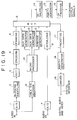
- Fig. 19 is a block diagram of a signal processing circuit of the recording and transmitting side of a digital recording and reproducing device according to a first embodiment of the present invention.
- those components which have been described above are indicated by the same reference numerals and in the interest of brevity, further description thereof is omitted.
- the circuit shown in Fig. 19 receives input analog composite video signals, which include video information and copy protection information, and input analog audio signals, which include audio information, and concurrently processes the input signals for digital recording onto a first recording medium and for transmission over a digital transmission line.
- the recorded audio and video signals include updated copy protection information which indicates that the input audio and video signals have been copied, and the transmitted audio and video signals include the original copy protection information so that the transmitted signals, or at least the information represented by the transmitted signals, subsequently may be recorded onto a second recording medium.
- the input analog composite video signal is supplied to the A/D processing circuit 1 and to the vertical blanking (VBLK) signal decoder circuit 9.
- the VBLK signal decoder circuit 9 decodes the copy protection information in the vertical blanking period of the video signal and delivers the copy protection information to a microprocessor 10 which determines therefrom whether copying of the video information is permitted. If copying is permitted, the microprocessor 10 generates a first SCMS code comprising updated copy protection information to indicate that the video information was copied and delivers this SCMS code to a first AUX data generating circuit 11.
- the first AUX data generating circuit 11 generates blocks of first accompanying video signals comprised of, for example, the packs of VAUX signals shown in Fig.
- the switching circuit combines the blocks of video signals and the blocks of first accompanying video signals and couples the combined signals to the deshuffling circuit 14 for further processing and subsequent recording on a first digital recording medium.
- the microprocessor 10 also generates a second SCMS code comprising the original copy protection information of the input analog composite video signal, if that copy protection information indicates that copying is permitted, and delivers the second SCMS code to a second AUX data generating circuit 12.
- the second AUX data generating circuit generates blocks of accompanying video signals formed of, for example, the packs of VAUX signals shown in Fig. 12(2) and which include the second SCMS code, and these blocks of accompanying video signals are supplied to the switching circuit 6 for transmission to (as opposed to recording by) another device.
- the switching circuit couples the blocks of video signals and the blocks of accompanying video signals, as well as the interleaved audio signals, the accompanying audio signals and the formatted subcode signals described with reference to Fig. 1, to the packetizing circuit 17 for further processing, as described with reference to Fig. 17, and subsequent transmission over a digital transmission line via a digital interface.
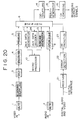
- Fig. 20 is a block diagram of another signal processing circuit that may be disposed at the receiving and recording side of a digital recording and reproducing device.
- This circuit receives the digital video signals that are transmitted by the circuit shown in Fig. 19 over the digital transmission line and processes those signals for recording onto a digital recording medium. It is appreciated that the received digital video signals include video information and copy protection information.
- blocks of video signals and blocks of accompanying video signals which are derived from the received digital video signals as described above in conjunction with Fig. 16, are delivered by a depacketizing circuit 23 to the switching circuit 6.
- the switching circuit supplies the blocks of received accompanying video signals to the AUX data decoder 24 which decodes the copy protection information from those blocks and supplies the copy protection information to microprocessor 10.
- the microprocessor interprets the copy protection information to determine whether copying of the received video information is permitted and, if so, generates an updated SCMS code comprising updated copy protection information that indicates that the video information was copied.
- the updated SCMS code is supplied from the microprocessor to the AUX data generating circuit 11 which generates blocks of second accompanying video signals formed of, for example, the packs of VAUX signals shown in Fig. 12(2) and containing the updated SCMS code.
- the blocks of second accompanying video signals are supplied to the switching circuit 6 which combines the blocks of received digital video signals and the blocks of second accompanying video signals and delivers the combined signals to the deshuffling circuit 14 for further processing and recording on the digital medium as described above with reference to Fig. 16.
- the circuits shown in Figs. 19 and 20 are operable to dub an original recording concurrently onto two or more copy media.
- the signal processing circuit shown in Fig. 19 preferably arranged as the recording and transmission circuit 52 in Fig. 18C and the signal processing circuit shown in Fig. 20 preferably is arranged as the recording circuit 54, thereby permitting an original recording (in which the accompanying copy protection information permits the copying of the original recording but does not permit copying from a copy) onto first and second copy media.
- the original recording on recording medium 50 is reproduced by reproducing circuit 51 and is outputted as analog audio and video signals to the recording and transmission circuit 52, which includes the circuit shown in Fig. 19.
- the recording and transmission circuit 52 generates updated copy protection information that indicates that the video information was copied and records this updated copy protection information along with the reproduced recording onto first copy recording medium 53.
- the recording and transmission circuit 52 also transmits the original copy protection information with the reproduced recording over the digital transmission line to the recording circuit 54, which includes the circuit shown in Fig. 20. Because the original copy protection information indicates that further copying is permitted, the recording circuit 54 records the reproduced recording onto second copy recording medium 55 along with the updated copy protection information.
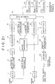
- Fig. 21 is a block diagram of a signal processing circuit of the recording and transmitting side of a digital recording and reproducing device according to another embodiment of the present invention.
- the circuit shown in Fig. 21 processes input analog composite video signals, which include video information and copy protection information, as well as input analog audio signals, which include audio information, for recording onto a digital recording medium and for concurrent transmission over a digital transmission line.
- the recorded audio and video signals, as well as the transmitted audio and video signals include updated copy protection information which indicates that the audio and video signals have been copied.
- the transmitted audio and video signals also include header signals formed of the original input copy protection information so that the transmitted audio and video information subsequently may be recorded onto a second recording medium.
- an input analog composite video signal is supplied to A/D processing circuit 1 for digital conversion, and to vertical blanking (VBLK) signal decoder circuit 9.
- the VBLK signal decoder circuit decodes the copy protection information included in the vertical blanking period of the input video signal and supplies the copy protection information to microprocessor 10.
- the microprocesssor determines from the copy protection information whether copying of the video information is permitted and, if so, generates a first SCMS code comprising updated copy protection information that indicates that the video information was copied.
- the microprocessor couples this first SCMS code to the AUX data generating circuit 11 which generates blocks of accompanying video signals comprised of, for example, the packs of VAUX signals shown in Fig.
- the switching circuit combines the blocks of video signals (received from framing circuit 5) and the blocks of accompanying video signals and supplies the combined signals to the deshuffling circuit 14 for further processing and subsequent recording onto the digital recording medium.
- the microprocessor 10 further generates a second SCMS code comprised of the original copy protection information, if that information indicates that copying is permitted, and supplies the second SCMS code to packetizing circuit 17.
- the microprocessor also instructs the packetizing circuit to generate a header packet H0 which includes the original copy protection information and has the format shown in Fig. 22.
- the second SCMS code is stored in the second and third most significant bits of bytes 5 and 6 of the header packet H0 and represents the copy protection information of the video signal.
- the second SCMS code is stored in the second and third most significant bits of the sixth byte of the header packet H0.
- the switching circuit 6 also supplies the blocks of video signals derived from the input video signals and the accompanying video signals generated by AUX data generator 11, as well as the interleaved audio signals, the accompanying audio signals and the formatted subcode signals described above with reference to Fig. 1, to the packetizing circuit 17.
- the packetizing circuit arranges the signals into packets and appends the packets to the header packet H0 in the predefined sequence shown in Fig. 23. As shown, in Fig. 23, the packets representing one track of a video frame are arranged in the sequence H0, SC0, SC1, VA0, VA1, VA2, A0, V0, V1, V2, ... V14, A1, V15, V16, .... V134.
- Each of the packets SC0 and SC1 includes six of the twelve synch blocks of formatted subcode data shown in Fig. 13; each of the packets VA0, VA1 and VA2 includes one of the three VAUX synch blocks shown in Fig. 10; each of the packets A0, A1 ... A8 includes one of the nine audio synch blocks shown in Fig. 5A; and each of the packets V0, V1 ... V134 include one of the 135 video synch blocks shown in Fig. 6.
- the packetizing circuit 17 supplies the packets to parity generator circuit 18 for further processing, and transmission over the digital transmission line via the digital interface.
- Fig. 24 is a block diagram of a signal processing circuit of the receiving and recording side of a digital recording and reproducing device compatible with and complementary to the circuit shown in Fig. 21.
- the digital video signals that are transmitted by the circuit shown in Fig. 21 over the above-described digital transmission line are received and processed for recording onto a digital recording medium.
- the received digital video signals include video information and copy protection information formed of the packets SC0 .... V134 shown in Fig. 23.
- These packets are received by receiver circuit 21, error detected by error detecting circuit 22, and converted to blocks of received video signals and blocks of accompanying video signals by depacketizing circuit 23 which are supplied to switching circuit 6.
- the depacketizing circuit 23 also converts the header packet H0 into the second SCMS code, comprised of the original copy protection information, which is coupled to the microprocessor 10.
- the microprocessor interprets the original copy protection information included in the header packet H0 to determine whether copying of the video information is permitted, and if so, generates an updated SCMS code formed of updated copy protection information that indicates that the video information was copied.
- the microprocessor couples the updated SCMS code to the AUX data generating circuit 11 which generates blocks of accompanying video signals formed of, for example, the packs of VAUX signals shown in Fig. 12(2) and having the updated SCMS code.
- the AUX data generating circuit supplies the generated blocks of accompanying video signals to the switching circuit 6 which combines these blocks with the blocks of video signals and couples the combined signals to the deshuffling circuit 14 for further processing and subsequent recording onto the digital recording medium.
- the microprocessor instructs the switching circuit 6 to combine the blocks of received video signals and the received blocks of accompanying video signals, which include the updated copy protection information, and to supply the combined blocks to the deshuffling circuit 14 for further processing and recording as described above.
- the circuits shown in Figs, 21 and 24 are operable to concurrently dub an original recording onto two or more copies.
- the signal processing circuit shown in Fig. 21 is arranged, for example, as the recording and transmission circuit 52, and the signal processing circuit shown in Fig. 24 is arranged as the recording circuit 54 shown in Fig. 18C to copy an original recording onto first and second copy media even if the copy protection information permits the copying of the original recording but does not permit copying from a copy.
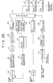
- Fig. 25 is block diagram of another embodiment of a signal processing circuit of the receiving, recording and transmitting side of a digital recording and reproducing device.
- Digital video signals that are transmitted over a digital transmission line by a signal processing circuit of the type shown in Fig. 19 are received and concurrently processed for recording onto a digital recording medium and for output as analog composite video signals and audio signals.
- the received video signals include blocks of video signals and blocks of accompanying video signals, which are supplied by depacketizing circuit 23 to the switching circuit 6.
- the switching circuit delivers the blocks of accompanying video signals to the AUX data decoder 24 which decodes the copy protection information included therein and supplies the copy protection information to the microprocessor 10.
- the microprocessor determines from the copy protection information whether copying of the video information is permitted and, if so, generates a first SCMS code which comprises updated copy protection information indicating that the video information was copied.
- the microprocessor supplies this first SCMS code to the AUX data generating circuit 11 which generates blocks of accompanying video signals comprised of, for example, the packs of VAUX signals shown in Fig. 12(2) and which include the first SCMS code, and supplies the blocks of accompanying video signals to the switching circuit for combining with the blocks of received video signals.
- the combined signals are coupled to the deshuffling circuit 14 for further processing and subsequent recording onto a digital recording medium.
- the switching circuit 6 also supplies the blocks of video signals to deframing circuit 29 for further processing, as described above with reference to Fig. 14, and subsequent delivery to a combining circuit 38 which provides an output analog video signal.
- the microprocessor 10 also generates a second SCMS code comprising the original copy protection information, and supplies the second SCMS code to the vertical blanking (VBLK) signal generator 37 which generates an analog copy protection signal based on this second SCMS code and delivers the analog copy protection signal to the combining circuit 38.
- the combining circuit inserts the analog copy protection signal into the vertical blanking period of the output analog composite video signal which is couple to the output terminal.
- the circuits shown in Figs. 19 and 25 are operable to concurrently dub an original recording onto two or more copies.
- the signal processing circuit shown in Fig. 19 is arranged, for example, as the recording and transmission circuit 52 and the signal processing circuit shown in Fig. 25 is arranged as the recording circuit 54 shown in Fig. 18C to copy an original recording, in which the copy protection information permits copying of the original recording but does not permit copying from the copy, onto first and second copy media.
- the original recording stored on recording medium 50 is reproduced by reproducing circuit 51 and is outputted to the recording and transmission circuit 52 shown in Fig. 19.
- the recording and transmission circuit 52 generates updated copy protection information that indicates that the video information was copied and records this updated copy protection information with the reproduced recording onto the first copy recording medium 53.
- the recording and transmission circuit 52 also transmits the original copy protection information with the reproduced recording via the digital transmission line to the recording circuit 54, shown in Fig. 25, and because the original copy protection information indicates that further copying is permitted, the recording circuit 54 records the reproduced recording with the updated copy protection information onto the second copy recording medium 55.
- embodiments of the present invention provide apparatus and methods for recording and reproducing video signals which contain copy protection information that restricts the number of times the video information may be copied; and/or apparatus and methods to concurrently dub from an original recording onto one or more copies video signals that include copy protection information which restricts the number of times the video signals may be is copied.
Landscapes
- Engineering & Computer Science (AREA)
- Multimedia (AREA)
- Signal Processing (AREA)
- Signal Processing For Digital Recording And Reproducing (AREA)
- Television Signal Processing For Recording (AREA)
Priority Applications (1)
| Application Number | Priority Date | Filing Date | Title |
|---|---|---|---|
| EP01201209A EP1133182B1 (fr) | 1994-02-15 | 1995-02-14 | Appareil d'enregistrement et de reproduction de signal vidéo |
Applications Claiming Priority (3)
| Application Number | Priority Date | Filing Date | Title |
|---|---|---|---|
| JP40450/94 | 1994-02-15 | ||
| JP04045094A JP3321972B2 (ja) | 1994-02-15 | 1994-02-15 | ディジタル信号記録装置 |
| JP4045094 | 1994-02-15 |
Related Child Applications (1)
| Application Number | Title | Priority Date | Filing Date |
|---|---|---|---|
| EP01201209A Division EP1133182B1 (fr) | 1994-02-15 | 1995-02-14 | Appareil d'enregistrement et de reproduction de signal vidéo |
Publications (3)
| Publication Number | Publication Date |
|---|---|
| EP0667720A2 true EP0667720A2 (fr) | 1995-08-16 |
| EP0667720A3 EP0667720A3 (fr) | 1995-11-29 |
| EP0667720B1 EP0667720B1 (fr) | 2001-11-07 |
Family
ID=12580983
Family Applications (2)
| Application Number | Title | Priority Date | Filing Date |
|---|---|---|---|
| EP95300889A Expired - Lifetime EP0667720B1 (fr) | 1994-02-15 | 1995-02-14 | Appareil d'enregistrement et de reproduction de signaux vidéo |
| EP01201209A Expired - Lifetime EP1133182B1 (fr) | 1994-02-15 | 1995-02-14 | Appareil d'enregistrement et de reproduction de signal vidéo |
Family Applications After (1)
| Application Number | Title | Priority Date | Filing Date |
|---|---|---|---|
| EP01201209A Expired - Lifetime EP1133182B1 (fr) | 1994-02-15 | 1995-02-14 | Appareil d'enregistrement et de reproduction de signal vidéo |
Country Status (4)
| Country | Link |
|---|---|
| US (2) | US5673357A (fr) |
| EP (2) | EP0667720B1 (fr) |
| JP (1) | JP3321972B2 (fr) |
| DE (2) | DE69533241T2 (fr) |
Cited By (11)
| Publication number | Priority date | Publication date | Assignee | Title |
|---|---|---|---|---|
| EP0762758A3 (fr) * | 1995-09-01 | 1997-05-28 | Sony Corp | Protection numérique contre la copie vidéo |
| EP0762759A3 (fr) * | 1995-09-01 | 1997-06-04 | Sony Corp | Enregistrement de données |
| EP0762417A3 (fr) * | 1995-08-25 | 1999-01-27 | Sony Corporation | Enregistrement et reproduction de signaux,support d'enregistrement de signaux et transmission et réception de signaux |
| EP0944256A1 (fr) * | 1998-03-19 | 1999-09-22 | Hitachi Europe Limited | Procedé et appareil pour la protection contre la copiage |
| EP0906693A4 (fr) * | 1996-06-19 | 2000-12-13 | Sony Electronics Inc | Systeme d'acces conditionnel pour un dispositif de memorisation local |
| EP0789361A3 (fr) * | 1996-02-06 | 2001-01-03 | Matsushita Electric Industrial Co., Ltd. | Appareil de réception de données, appareil de transmission de données, système de traitement d'information, méthode de réception de données et milieu d'enregistrement d'information pour le stockage de la méthode de réception de données utilisable pour prévenir la copie illégale de documents |
| EP1124383A3 (fr) * | 2000-02-10 | 2002-01-30 | Nec Corporation | Méthode et système de contrôle de duplication pour données vidéo numériques |
| US6377968B1 (en) | 1998-04-16 | 2002-04-23 | Hitachi, Ltd. | Digital filtering circuit |
| EP0769780B1 (fr) * | 1995-10-18 | 2003-01-29 | Matsushita Electric Industrial Co., Ltd. | Dispositif d'enregistrement d'information et dispositif émetteur d'information |
| SG97761A1 (en) * | 1997-02-24 | 2003-08-20 | Nec Corp | Digital data encode system |
| EP1130916A3 (fr) * | 2000-03-03 | 2004-01-21 | Matsushita Electric Industrial Co., Ltd. | Appareil d'enregistrement et de reproduction |
Families Citing this family (54)
| Publication number | Priority date | Publication date | Assignee | Title |
|---|---|---|---|---|
| US5748763A (en) | 1993-11-18 | 1998-05-05 | Digimarc Corporation | Image steganography system featuring perceptually adaptive and globally scalable signal embedding |
| KR0152788B1 (ko) | 1994-11-26 | 1998-10-15 | 이헌조 | 디지탈 영상 시스템의 복사 방지 방법 및 장치 |
| KR0136458B1 (ko) | 1994-12-08 | 1998-05-15 | 구자홍 | 디지탈 자기 기록재생 시스템의 복사 방지장치 |
| US6687828B1 (en) | 1995-08-11 | 2004-02-03 | Sony Corporation | Method and apparatus for ciphering playback mode information for recording on record medium |
| JP4518574B2 (ja) * | 1995-08-11 | 2010-08-04 | ソニー株式会社 | 記録方法及び装置、記録媒体、並びに再生方法及び装置 |
| JP3341546B2 (ja) * | 1995-10-05 | 2002-11-05 | ソニー株式会社 | デジタル画像信号の記録再生方法及び記録再生装置 |
| JP3613858B2 (ja) * | 1995-10-26 | 2005-01-26 | ソニー株式会社 | テレビジョン信号の伝送または記録方法、および記録装置 |
| JP3371187B2 (ja) * | 1995-12-04 | 2003-01-27 | ソニー株式会社 | 情報信号記録装置および方法、並びに情報信号複製装置および方法 |
| JP3405034B2 (ja) * | 1995-12-27 | 2003-05-12 | ソニー株式会社 | ディジタル信号多重化方法及び装置、並びにディジタル信号記録媒体 |
| US6011765A (en) * | 1996-04-12 | 2000-01-04 | Sony Corporation | Recording medium having copying protection signals recorded in superposition on main signals |
| JPH103745A (ja) * | 1996-06-12 | 1998-01-06 | Sony Corp | 記録媒体、デジタルコピー管理方法、再生装置、及び記録装置 |
| JP3941178B2 (ja) | 1996-09-05 | 2007-07-04 | ソニー株式会社 | 記録媒体、デジタル記録機器、及び制御用ic |
| US6298196B1 (en) | 1996-09-05 | 2001-10-02 | Sony Corporation | Digital recording apparatus and copyright protection method thereof |
| US7221853B1 (en) | 1996-09-05 | 2007-05-22 | Sony Corporation | Digital recording apparatus and copyright protection method thereof |
| JP3736588B2 (ja) * | 1996-11-18 | 2006-01-18 | ソニー株式会社 | 情報出力装置、情報出力方法、記録装置および情報複製防止制御方法 |
| JP3700738B2 (ja) * | 1996-11-18 | 2005-09-28 | ソニー株式会社 | 情報出力装置、情報出力方法、記録装置および記録方法 |
| US6282684B1 (en) | 1997-10-23 | 2001-08-28 | Sony Corporation | Apparatus and method for recovery of data in a lossy transmission environment |
| US6581170B1 (en) * | 1997-10-23 | 2003-06-17 | Sony Corporation | Source coding to provide for robust error recovery during transmission losses |
| US6212663B1 (en) | 1997-10-23 | 2001-04-03 | Sony Corporation | Apparatus and method for recovery of quantization codes in a lossy transmission environment |
| JP4106740B2 (ja) * | 1998-02-18 | 2008-06-25 | ソニー株式会社 | 情報記録装置および方法、情報再生装置および方法、並びにプログラム記録媒体 |
| JP3697064B2 (ja) * | 1998-05-29 | 2005-09-21 | キヤノン株式会社 | 画像編集装置、記録装置、画像編集方法及びコンピュータ読み取り可能な記録媒体 |
| US6539054B1 (en) * | 1998-09-18 | 2003-03-25 | Matsushita Electric Industrial Co., Ltd. | Image output apparatus, image reproduction method, object composition apparatus, object composition method, and data storage medium |
| US6519369B1 (en) | 1999-02-12 | 2003-02-11 | Sony Corporation | Method and apparatus for filter tap expansion |
| US6418548B1 (en) | 1999-02-12 | 2002-07-09 | Sony Corporation | Method and apparatus for preprocessing for peripheral erroneous data |
| US6535148B1 (en) | 1999-02-12 | 2003-03-18 | Sony Corporation | Method and apparatus for truncated decoding |
| US6621936B1 (en) | 1999-02-12 | 2003-09-16 | Sony Corporation | Method and apparatus for spatial class reduction |
| US6591398B1 (en) | 1999-02-12 | 2003-07-08 | Sony Corporation | Multiple processing system |
| US6170074B1 (en) | 1999-02-12 | 2001-01-02 | Sony Corporation | Source coding to provide for robust error recovery |
| US6307560B1 (en) | 1999-02-12 | 2001-10-23 | Sony Corporation | Classified adaptive spatio-temporal format conversion method and apparatus |
| US7010737B2 (en) * | 1999-02-12 | 2006-03-07 | Sony Corporation | Method and apparatus for error data recovery |
| US6307979B1 (en) | 1999-02-12 | 2001-10-23 | Sony Corporation | Classified adaptive error recovery method and apparatus |
| US6363118B1 (en) | 1999-02-12 | 2002-03-26 | Sony Corporation | Apparatus and method for the recovery of compression constants in the encoded domain |
| JP3816689B2 (ja) * | 1999-03-31 | 2006-08-30 | 株式会社東芝 | 情報配信装置、情報受信装置及び通信方法 |
| EP1089274B1 (fr) | 1999-04-16 | 2007-11-14 | Sony Corporation | Systeme de traitement de donnees, procede de traitement de donnees et processeur de donnees |
| US6473876B1 (en) | 1999-06-29 | 2002-10-29 | Sony Corporation | Method and apparatus for encoding of bitstreams using rotation |
| US6493842B1 (en) | 1999-06-29 | 2002-12-10 | Sony Corporation | Time-varying randomization for data synchronization and implicit information transmission |
| US6389562B1 (en) | 1999-06-29 | 2002-05-14 | Sony Corporation | Source code shuffling to provide for robust error recovery |
| US6549672B1 (en) | 1999-06-29 | 2003-04-15 | Sony Corporation | Method and apparatus for recovery of encoded data using central value |
| US6522785B1 (en) | 1999-09-24 | 2003-02-18 | Sony Corporation | Classified adaptive error recovery method and apparatus |
| US6351494B1 (en) | 1999-09-24 | 2002-02-26 | Sony Corporation | Classified adaptive error recovery method and apparatus |
| US6539517B1 (en) | 1999-11-09 | 2003-03-25 | Sony Corporation | Data transformation for explicit transmission of control information |
| US6754371B1 (en) | 1999-12-07 | 2004-06-22 | Sony Corporation | Method and apparatus for past and future motion classification |
| JP2001309322A (ja) * | 2000-04-27 | 2001-11-02 | Sony Corp | 信号伝送方法及び信号伝送装置、信号受信方法及び信号受信装置、vbi信号発生装置、ビデオ信号送信装置、ビデオ信号処理装置、ビデオ信号受信装置、解読装置、並びに、ビデオ信号を記録する記録媒体 |
| US7978613B2 (en) * | 2000-05-26 | 2011-07-12 | British Telecommunications Public Limited Company | Test signalling |
| US7571244B2 (en) * | 2000-07-15 | 2009-08-04 | Filippo Costanzo | Audio-video data switching and viewing system |
| JP4934923B2 (ja) * | 2001-08-09 | 2012-05-23 | ソニー株式会社 | 情報記録装置、情報再生装置、および情報記録方法、情報再生方法、並びにコンピュータ・プログラム |
| US7398008B2 (en) * | 2002-09-19 | 2008-07-08 | Hewlett-Packard Development Company, L.P. | Copy protection for analog video signals from computing devices |
| CN100555441C (zh) * | 2003-02-28 | 2009-10-28 | 松下电器产业株式会社 | 再现装置、记录方法再现方法 |
| US20060204212A1 (en) * | 2004-08-31 | 2006-09-14 | Minoru Kinaka | Information recording/reproducing device |
| US7836216B2 (en) * | 2005-08-23 | 2010-11-16 | Palm, Inc. | Connector system for supporting multiple types of plug carrying accessory devices |
| US7734841B2 (en) * | 2006-06-30 | 2010-06-08 | Palm, Inc. | System and method for providing serial bus connectivity |
| CN101611323B (zh) * | 2006-09-29 | 2013-02-20 | 密理博公司 | 流式细胞术脉冲的区分和应用 |
| FI20065783A0 (sv) * | 2006-12-08 | 2006-12-08 | Nokia Corp | Signalfördistorsion i radiosändare |
| US8787726B2 (en) | 2012-02-26 | 2014-07-22 | Antonio Rossi | Streaming video navigation systems and methods |
Family Cites Families (12)
| Publication number | Priority date | Publication date | Assignee | Title |
|---|---|---|---|---|
| JPS5954388A (ja) * | 1982-09-22 | 1984-03-29 | Victor Co Of Japan Ltd | デイジタルビデオ信号再生装置 |
| US5057947A (en) * | 1988-02-10 | 1991-10-15 | Matsushita Electric Industrial Co., Ltd. | Recording and reproducing apparatus with limited digital copying |
| JP2797404B2 (ja) * | 1989-04-20 | 1998-09-17 | ソニー株式会社 | 動画像データの記録方式 |
| JP3273781B2 (ja) * | 1989-09-21 | 2002-04-15 | コーニンクレッカ フィリップス エレクトロニクス エヌ ヴイ | 記録担体及び記録担体を得る方法及び装置及び複写防止手段を持つ情報記録装置 |
| JPH0727715B2 (ja) * | 1989-11-24 | 1995-03-29 | シャープ株式会社 | ディジタルオーディオインターフェイス信号中継装置 |
| KR920006995B1 (ko) * | 1990-06-27 | 1992-08-24 | 삼성전자 주식회사 | 디지탈신호 재생처리장치 |
| JP2883449B2 (ja) * | 1990-12-27 | 1999-04-19 | 株式会社東芝 | 記録装置 |
| DE69225346T2 (de) * | 1991-02-07 | 1998-09-03 | Matsushita Electric Ind Co Ltd | Verfahren und Vorrichtung zur Übertragung und Reproduktion von einem digitalen Signal |
| TW221507B (fr) * | 1992-06-16 | 1994-03-01 | Matsushita Electric Industrial Co Ltd | |
| JPH0644755A (ja) * | 1992-07-24 | 1994-02-18 | Sony Corp | ビデオ信号の伝送方法及び記録装置 |
| JP3217137B2 (ja) * | 1992-07-28 | 2001-10-09 | 株式会社日立製作所 | 映像信号記録装置、再生装置及び伝送装置 |
| US5315448A (en) * | 1993-03-18 | 1994-05-24 | Macrovision Corporation | Copy protection for hybrid digital video tape recording and unprotected source material |
-
1994
- 1994-02-15 JP JP04045094A patent/JP3321972B2/ja not_active Expired - Lifetime
-
1995
- 1995-02-14 EP EP95300889A patent/EP0667720B1/fr not_active Expired - Lifetime
- 1995-02-14 US US08/388,499 patent/US5673357A/en not_active Expired - Lifetime
- 1995-02-14 DE DE69533241T patent/DE69533241T2/de not_active Expired - Lifetime
- 1995-02-14 DE DE69523650T patent/DE69523650T2/de not_active Expired - Lifetime
- 1995-02-14 EP EP01201209A patent/EP1133182B1/fr not_active Expired - Lifetime
-
1997
- 1997-05-22 US US08/861,985 patent/US5907657A/en not_active Expired - Lifetime
Cited By (29)
| Publication number | Priority date | Publication date | Assignee | Title |
|---|---|---|---|---|
| US6345145B1 (en) | 1995-08-25 | 2002-02-05 | Sony Corporation | Signal recording/reproducing method and apparatus, signal record medium and signal transmission/reception method and apparatus |
| US8301014B2 (en) | 1995-08-25 | 2012-10-30 | Sony Corporation | Signal recording/reproducing method and apparatus, signal record medium and signal transmission/reception method and apparatus |
| US7428369B2 (en) | 1995-08-25 | 2008-09-23 | Sony Corporation | Signal recording/reproducing method and apparatus, signal record medium and signal transmission/reception method and apparatus |
| EP0762417A3 (fr) * | 1995-08-25 | 1999-01-27 | Sony Corporation | Enregistrement et reproduction de signaux,support d'enregistrement de signaux et transmission et réception de signaux |
| US6363209B2 (en) | 1995-08-25 | 2002-03-26 | Sony Corporation | Signal recording/reproducing method and apparatus, signal record medium and signal |
| US6345146B1 (en) | 1995-08-25 | 2002-02-05 | Sony Corporation | Signal recording/reproducing method and apparatus, signal record medium and signal transmission/reception method and apparatus |
| EP1359754A3 (fr) * | 1995-09-01 | 2004-03-03 | Sony Corporation | Protection contre la copie de vidéo numérique |
| US5703859A (en) * | 1995-09-01 | 1997-12-30 | Sony Corporation | Digital video copy protection system |
| EP1085754A1 (fr) * | 1995-09-01 | 2001-03-21 | Sony Corporation | Système pour l'acquisition et la reproduction de programmes de télévision |
| US6266482B1 (en) * | 1995-09-01 | 2001-07-24 | Sony Corporation | Data recording apparatus and method for preventing illegal copying |
| US6295407B1 (en) | 1995-09-01 | 2001-09-25 | Sony Corporation | Digital video copy protection system |
| EP0762759A3 (fr) * | 1995-09-01 | 1997-06-04 | Sony Corp | Enregistrement de données |
| EP0762758A3 (fr) * | 1995-09-01 | 1997-05-28 | Sony Corp | Protection numérique contre la copie vidéo |
| US5991499A (en) * | 1995-09-01 | 1999-11-23 | Sony Corporation | Data recording apparatus and method for preventing illegal copying |
| EP0769780B1 (fr) * | 1995-10-18 | 2003-01-29 | Matsushita Electric Industrial Co., Ltd. | Dispositif d'enregistrement d'information et dispositif émetteur d'information |
| EP0789361A3 (fr) * | 1996-02-06 | 2001-01-03 | Matsushita Electric Industrial Co., Ltd. | Appareil de réception de données, appareil de transmission de données, système de traitement d'information, méthode de réception de données et milieu d'enregistrement d'information pour le stockage de la méthode de réception de données utilisable pour prévenir la copie illégale de documents |
| EP0906693A4 (fr) * | 1996-06-19 | 2000-12-13 | Sony Electronics Inc | Systeme d'acces conditionnel pour un dispositif de memorisation local |
| EP2081380A3 (fr) * | 1996-06-19 | 2010-09-08 | Sony Electronics, Inc. | Système d'acces conditionnel pour un dispositif de memorisation local |
| EP2068562A3 (fr) * | 1996-06-19 | 2010-09-08 | Sony Electronics, Inc. | Système d'acces conditionnel pour un dispositif de memorisation local |
| EP1732319A3 (fr) * | 1996-06-19 | 2008-08-20 | Sony Electronics Inc. | Système d'acces conditionnel pour un dispositif de memorisation local |
| SG97761A1 (en) * | 1997-02-24 | 2003-08-20 | Nec Corp | Digital data encode system |
| US6865553B2 (en) | 1998-03-19 | 2005-03-08 | Hitachi, Ltd. | Copy protection apparatus and method |
| EP0944256A1 (fr) * | 1998-03-19 | 1999-09-22 | Hitachi Europe Limited | Procedé et appareil pour la protection contre la copiage |
| US6310956B1 (en) | 1998-03-19 | 2001-10-30 | Hitachi, Ltd. | Copy protection apparatus and method |
| US6675183B2 (en) | 1998-04-16 | 2004-01-06 | Hitachi, Ltd. | Digital filtering circuit |
| US6377968B1 (en) | 1998-04-16 | 2002-04-23 | Hitachi, Ltd. | Digital filtering circuit |
| US7151887B2 (en) | 2000-02-10 | 2006-12-19 | Nec Corporation | Copy controlling method and system of digital contents |
| EP1124383A3 (fr) * | 2000-02-10 | 2002-01-30 | Nec Corporation | Méthode et système de contrôle de duplication pour données vidéo numériques |
| EP1130916A3 (fr) * | 2000-03-03 | 2004-01-21 | Matsushita Electric Industrial Co., Ltd. | Appareil d'enregistrement et de reproduction |
Also Published As
| Publication number | Publication date |
|---|---|
| EP1133182A1 (fr) | 2001-09-12 |
| DE69533241D1 (de) | 2004-08-12 |
| DE69523650T2 (de) | 2002-08-14 |
| EP0667720B1 (fr) | 2001-11-07 |
| DE69523650D1 (de) | 2001-12-13 |
| JP3321972B2 (ja) | 2002-09-09 |
| JPH07226915A (ja) | 1995-08-22 |
| EP0667720A3 (fr) | 1995-11-29 |
| DE69533241T2 (de) | 2005-06-30 |
| US5673357A (en) | 1997-09-30 |
| EP1133182B1 (fr) | 2004-07-07 |
| US5907657A (en) | 1999-05-25 |
Similar Documents
| Publication | Publication Date | Title |
|---|---|---|
| EP1133182B1 (fr) | Appareil d'enregistrement et de reproduction de signal vidéo | |
| CA2187077C (fr) | Magnetoscope a cassettes numerique a commande d'image de reproduction speciale | |
| EP0682421B1 (fr) | Procédé et dispositif pour enregistrer d'un signal audio numérique composé d'une pluralité de canaux audiophonique, et procédé et dispositif pour reproduire lesquels | |
| US5583654A (en) | Digital video and audio signal recording and reproducing apparatus efficiently storing a variety of different accompanying video and audio information data | |
| EP0675612B1 (fr) | Dispositif de transmission, réproduction et enrégistrement de signaux de son numérique | |
| EP0853437A2 (fr) | Appareil d'enregistrement et de reproduction d'un signal vidéo | |
| EP0667714B1 (fr) | Appareil d'enregistrement d'un signal vidéo numérique | |
| EP0711085B1 (fr) | Enregistrement et reproduction de signaux de télévision | |
| JP3385623B2 (ja) | ディジタル情報信号の伝送装置 | |
| US6009235A (en) | Digital signal recording/reproducing apparatus | |
| EP0667715B1 (fr) | Méthodes et dispositifs pour transmettre des données numériques comprimées à partir d'un dispositif enregistreur/lecteur | |
| JP3521495B2 (ja) | 音声信号記録方法、音声信号再生装置、及び音声信号記録再生方法 | |
| JP3477753B2 (ja) | 記録再生装置 | |
| JP3277458B2 (ja) | プリンタ装置 | |
| JP3493729B2 (ja) | ディジタルビデオおよびオーディオ信号記録/再生装置および方法 | |
| JPH07296519A (ja) | ディジタルオーディオ信号伝送装置 | |
| JPH07212699A (ja) | ディジタル画像・音声信号記録再生装置 | |
| JPH08223600A (ja) | テレビジョン信号の記録装置、再生装置、及び記録再生装置 | |
| JPH08214330A (ja) | テレビジョン信号の記録装置、再生装置、及び記録再生装置 |
Legal Events
| Date | Code | Title | Description |
|---|---|---|---|
| PUAI | Public reference made under article 153(3) epc to a published international application that has entered the european phase |
Free format text: ORIGINAL CODE: 0009012 |
|
| AK | Designated contracting states |
Kind code of ref document: A2 Designated state(s): DE FR GB NL |
|
| PUAL | Search report despatched |
Free format text: ORIGINAL CODE: 0009013 |
|
| AK | Designated contracting states |
Kind code of ref document: A3 Designated state(s): DE FR GB NL |
|
| 17P | Request for examination filed |
Effective date: 19960411 |
|
| 17Q | First examination report despatched |
Effective date: 19980525 |
|
| GRAG | Despatch of communication of intention to grant |
Free format text: ORIGINAL CODE: EPIDOS AGRA |
|
| GRAG | Despatch of communication of intention to grant |
Free format text: ORIGINAL CODE: EPIDOS AGRA |
|
| GRAH | Despatch of communication of intention to grant a patent |
Free format text: ORIGINAL CODE: EPIDOS IGRA |
|
| GRAH | Despatch of communication of intention to grant a patent |
Free format text: ORIGINAL CODE: EPIDOS IGRA |
|
| GRAA | (expected) grant |
Free format text: ORIGINAL CODE: 0009210 |
|
| AK | Designated contracting states |
Kind code of ref document: B1 Designated state(s): DE FR GB NL |
|
| REF | Corresponds to: |
Ref document number: 69523650 Country of ref document: DE Date of ref document: 20011213 |
|
| REG | Reference to a national code |
Ref country code: GB Ref legal event code: IF02 |
|
| PLBE | No opposition filed within time limit |
Free format text: ORIGINAL CODE: 0009261 |
|
| STAA | Information on the status of an ep patent application or granted ep patent |
Free format text: STATUS: NO OPPOSITION FILED WITHIN TIME LIMIT |
|
| 26N | No opposition filed | ||
| PGFP | Annual fee paid to national office [announced via postgrant information from national office to epo] |
Ref country code: NL Payment date: 20140218 Year of fee payment: 20 Ref country code: DE Payment date: 20140219 Year of fee payment: 20 |
|
| PGFP | Annual fee paid to national office [announced via postgrant information from national office to epo] |
Ref country code: FR Payment date: 20140219 Year of fee payment: 20 |
|
| PGFP | Annual fee paid to national office [announced via postgrant information from national office to epo] |
Ref country code: GB Payment date: 20140218 Year of fee payment: 20 |
|
| REG | Reference to a national code |
Ref country code: DE Ref legal event code: R071 Ref document number: 69523650 Country of ref document: DE |
|
| REG | Reference to a national code |
Ref country code: NL Ref legal event code: V4 Effective date: 20150214 |
|
| REG | Reference to a national code |
Ref country code: GB Ref legal event code: PE20 Expiry date: 20150213 |
|
| PG25 | Lapsed in a contracting state [announced via postgrant information from national office to epo] |
Ref country code: GB Free format text: LAPSE BECAUSE OF EXPIRATION OF PROTECTION Effective date: 20150213 |