EP0668146A1 - Procédé et dispositif pour la fabrication d'un article composite - Google Patents
Procédé et dispositif pour la fabrication d'un article composite Download PDFInfo
- Publication number
- EP0668146A1 EP0668146A1 EP95890029A EP95890029A EP0668146A1 EP 0668146 A1 EP0668146 A1 EP 0668146A1 EP 95890029 A EP95890029 A EP 95890029A EP 95890029 A EP95890029 A EP 95890029A EP 0668146 A1 EP0668146 A1 EP 0668146A1
- Authority
- EP
- European Patent Office
- Prior art keywords
- blanks
- cutting
- take
- roll
- station
- Prior art date
- Legal status (The legal status is an assumption and is not a legal conclusion. Google has not performed a legal analysis and makes no representation as to the accuracy of the status listed.)
- Withdrawn
Links
- 239000002131 composite material Substances 0.000 title claims abstract description 22
- 238000000034 method Methods 0.000 title claims abstract description 12
- 238000004519 manufacturing process Methods 0.000 title claims description 9
- 238000005520 cutting process Methods 0.000 claims abstract description 59
- 239000000463 material Substances 0.000 claims abstract description 37
- 238000003860 storage Methods 0.000 claims abstract description 34
- 230000003287 optical effect Effects 0.000 claims abstract description 8
- 238000003780 insertion Methods 0.000 claims description 36
- 230000037431 insertion Effects 0.000 claims description 36
- 239000002699 waste material Substances 0.000 claims description 12
- 238000004804 winding Methods 0.000 claims description 7
- 238000011144 upstream manufacturing Methods 0.000 claims description 4
- 230000000007 visual effect Effects 0.000 claims description 4
- 238000009434 installation Methods 0.000 claims 1
- 238000010276 construction Methods 0.000 description 3
- 239000011888 foil Substances 0.000 description 3
- 238000010586 diagram Methods 0.000 description 2
- 239000007858 starting material Substances 0.000 description 2
- 229920002430 Fibre-reinforced plastic Polymers 0.000 description 1
- 239000013256 coordination polymer Substances 0.000 description 1
- 230000007812 deficiency Effects 0.000 description 1
- 230000001419 dependent effect Effects 0.000 description 1
- 230000000694 effects Effects 0.000 description 1
- 239000011151 fibre-reinforced plastic Substances 0.000 description 1
- 238000000926 separation method Methods 0.000 description 1
Images

Classifications
-
- B—PERFORMING OPERATIONS; TRANSPORTING
- B29—WORKING OF PLASTICS; WORKING OF SUBSTANCES IN A PLASTIC STATE IN GENERAL
- B29C—SHAPING OR JOINING OF PLASTICS; SHAPING OF MATERIAL IN A PLASTIC STATE, NOT OTHERWISE PROVIDED FOR; AFTER-TREATMENT OF THE SHAPED PRODUCTS, e.g. REPAIRING
- B29C70/00—Shaping composites, i.e. plastics material comprising reinforcements, fillers or preformed parts, e.g. inserts
- B29C70/04—Shaping composites, i.e. plastics material comprising reinforcements, fillers or preformed parts, e.g. inserts comprising reinforcements only, e.g. self-reinforcing plastics
- B29C70/28—Shaping operations therefor
- B29C70/54—Component parts, details or accessories; Auxiliary operations, e.g. feeding or storage of prepregs or SMC after impregnation or during ageing
- B29C70/545—Perforating, cutting or machining during or after moulding
-
- B—PERFORMING OPERATIONS; TRANSPORTING
- B29—WORKING OF PLASTICS; WORKING OF SUBSTANCES IN A PLASTIC STATE IN GENERAL
- B29C—SHAPING OR JOINING OF PLASTICS; SHAPING OF MATERIAL IN A PLASTIC STATE, NOT OTHERWISE PROVIDED FOR; AFTER-TREATMENT OF THE SHAPED PRODUCTS, e.g. REPAIRING
- B29C70/00—Shaping composites, i.e. plastics material comprising reinforcements, fillers or preformed parts, e.g. inserts
- B29C70/04—Shaping composites, i.e. plastics material comprising reinforcements, fillers or preformed parts, e.g. inserts comprising reinforcements only, e.g. self-reinforcing plastics
- B29C70/28—Shaping operations therefor
- B29C70/30—Shaping by lay-up, i.e. applying fibres, tape or broadsheet on a mould, former or core; Shaping by spray-up, i.e. spraying of fibres on a mould, former or core
- B29C70/38—Automated lay-up, e.g. using robots, laying filaments according to predetermined patterns
- B29C70/386—Automated tape laying [ATL]
-
- B—PERFORMING OPERATIONS; TRANSPORTING
- B29—WORKING OF PLASTICS; WORKING OF SUBSTANCES IN A PLASTIC STATE IN GENERAL
- B29C—SHAPING OR JOINING OF PLASTICS; SHAPING OF MATERIAL IN A PLASTIC STATE, NOT OTHERWISE PROVIDED FOR; AFTER-TREATMENT OF THE SHAPED PRODUCTS, e.g. REPAIRING
- B29C70/00—Shaping composites, i.e. plastics material comprising reinforcements, fillers or preformed parts, e.g. inserts
- B29C70/04—Shaping composites, i.e. plastics material comprising reinforcements, fillers or preformed parts, e.g. inserts comprising reinforcements only, e.g. self-reinforcing plastics
- B29C70/28—Shaping operations therefor
- B29C70/54—Component parts, details or accessories; Auxiliary operations, e.g. feeding or storage of prepregs or SMC after impregnation or during ageing
- B29C70/543—Fixing the position or configuration of fibrous reinforcements before or during moulding
Definitions
- the invention relates to a method for producing a composite workpiece from a plurality of individual blanks, according to which the individual blanks are cut out of a flat material unwound from a donor roll together with a carrier foil as a tape, without cutting through the carrier foil, removed from the carrier foil and used to build up the workpiece in one certain order and arrangement can be inserted into a mold with visual indication of the respective insertion point.
- the construction of a composite workpiece from individual blanks allows material properties for the composite workpiece to be combined and, for example, direction-oriented strength properties of the blanks to be used to produce a workpiece with special properties.
- the blanks therefore usually also consist of fiber-reinforced plastics, in particular prepregs, and then lead to the desired workpiece properties on the basis of the predetermined sequence and arrangement in the construction of the workpiece. If blanks from prepregs or the like are used and these are inserted into insert molds, spatially designed composite workpieces can also be produced, whereby after inserting the blanks into the mold, heat and pressure treatment lead to hardening of the blanks and to completion of the workpiece.
- a special insertion station for inserting the blanks into the insertion mold, in which an optical display device, for example a laser device, is arranged above the insertion mold, with the aid of which the outline shape of the blanks to be inserted in each case is projected into the mold at the insertion point concerned, so that even when the blanks are inserted manually, they can be inserted in the correct order, arrangement and position.
- This insertion is, however, quite cumbersome despite the visual aid, since the individual blanks have to be found out by the respective worker from a plurality of blanks available and have to be removed from the strip material that is being spread, which not only leads to errors, but also difficulties in removing the blanks from the carrier film brings with it.
- the handling of the tape wound on the storage roll to remove the cut blanks is unsatisfactory due to the lack of a suitable removal device, so that the blanks are still removed in the cutting machine and only permit a slow workflow.
- the invention is therefore based on the object of eliminating these deficiencies and of specifying a method of the type described at the outset which simplifies and speeds up the production process in the production of composite workpieces and helps to avoid laying errors.
- a device for the rational implementation of this method is to be created.
- the invention solves this problem in that the blanks are continuously cut out of the flat material in a reverse order to the insertion and wound up with the carrier film onto a storage roll and that the tape is then unwound from the storage roll in steps predetermined by the successive cuts and with each unwinding step a blank is removed from the tape and inserted into the mold at the indicated position. If the blanks are continuously cut out of the material tape in the reverse order to laying and wound up on a storage roll, these blanks can then be removed one after the other in the correct order from the backing film of the tape when the storage roll is unwound and immediately inserted into the insert form.
- this step is stopped step by step to make it easier to remove, and the visual display immediately shows the worker the correct position of this blank that has just been removed in the insert form, so that it becomes one fast and, above all, error-free removal and insertion of the blanks.
- the tape is moved further after the step-by-step stopping as a function of the respective blank length, so that this tape movement simplifies the removal of the longer blanks.
- a system is provided with a cutting machine for cutting blanks from flat material strips, an insertion station for workpiece assembly and a control device, the cutting machine being a cutting tool that can be moved over the working surface of a cutting table and a cutting tool that can be adjusted to a specific cutting depth having cutting unit and the cutting table upstream or downstream in the feed direction, feed devices having roll receptacles for a dispenser roll or a storage roll for unwinding or winding up a flat material strip and the insertion station is provided with an optical display device arranged above an insertion mold for inserting the blanks.
- a removal station for removing from the flat material cut-out blanks set up, which comprises a take-off table with a take-off edge or the like provided at the end of the table and the take-up devices having roll receptacles for a storage roll or a waste roll upstream or downstream in the feed direction, and in the control device there is a shape,
- the position and arrangement of the individual blanks of a composite workpiece, a coordinated control program can be read in and the control device controls the cutting machine in the sense of continuously cutting out the individual blanks from the flat material strip and winding them onto the storage roll in the reverse order to the workpiece construction, and the removal station in the sense of a gradual unwinding dependent on the successive blanks the tape from the storage roll in the correct order for the workpiece assembly and the display device in the sense of the blanks to be inserted in this order into the insert form.
- the tape is stopped so that a worker can grasp the end of the blank now protruding from the carrier film and can easily remove the blank.
- the blank removed in this way is then simply carried into the insertion station provided next to the removal station, where the correct insertion point for the respective blank is already displayed on the optical display device by projecting the outline of the blank into the mold via this device, for example a laser device .
- the tape is moved further in the removal station until the next blank protrudes with its front end over the removal edge, so that the next blank can now be removed and put back into the insert form, where the correct one is now for this blank Insertion point is displayed.
- the cutting machine, removal station and loading station can be controlled without difficulty in such a way that the individual blanks are cut out in the reverse order to loading, that the tape is gradually unwound and stopped in the take-off station in accordance with the existing blanks and that the respective blanks are finally displayed in order in the correct order for insertion via the display device in the insert form.
- This control program not only controls the individual devices, but also their movements and work processes are coordinated with one another, so that smooth, fast and error-free production of composite workpieces is made possible.
- this cutting machine and the existing control device can of course have at least two removal stations and insertion stations can be assigned so that the storage rolls with the already cut blanks can be processed on different removal stations and insertion stations, which expands the manufacturing capacity of the system accordingly.
- the take-off station is equipped with an actuation switch for the feed device which is independent of the control device, since above all the removal of longer blanks can be facilitated by switching on the feed device and thus a continued belt movement.
- This switching on of the feed device can be carried out depending on a corresponding instruction of the worker, depending on an increased tightening of the blank and a tensile load on the strip or the like, but it does not interrupt the gradual unwinding of the strip from the beginning of the cut to the beginning of the cut.
- the removal station has a separating device for separating the cut waste from the carrier film, which separating device can be arranged before or after the removal edge, the cut waste can be removed before winding onto the waste roll and automatic separation of flat material waste and carrier film can be achieved.
- a separating device for separating the cut waste from the carrier film, which separating device can be arranged before or after the removal edge, the cut waste can be removed before winding onto the waste roll and automatic separation of flat material waste and carrier film can be achieved.
- Any suitable device can be used as the separating device, for example also a separating device as can be used in the cutting machine according to AT-B 393 983.
- end strips for winding and unwinding are provided for the flat material strips, which extension strips for example consist of paper or other worthless material and allow the clamping of the flat material strips in the cutting machine and the take-off station in such a way that the cutting or removal process can take place immediately with the actual start of the strip and an empty area for the clamping process does not have to be accepted.
- extension strips can be cut to length on the spot by a magazine roll and glued to the flat material strip, so that these strips can be extended to the required extent in a few steps in the course of clamping.
- a system 1 for producing composite workpieces from a plurality of individual blanks comprises a cutting machine 2 for cutting out the blanks from a flat material applied to a carrier film, a removal station 3 for removing the cut blanks from the carrier film and an insertion station 4 for assembling the composite workpieces from the blanks .
- the cutting machine 2 has a cutting table 21 with a working surface 22 and a cutting unit 23 which can be moved over this working surface and has an ultrasonic knife 24 which can be set to a specific cutting depth.
- a roll holder 25 for a dispenser roll 5 In the feed direction in front of the cutting table 21 there is a roll holder 25 for a dispenser roll 5 and in the feed direction after the cutting table 21 a roll holder 26 for a storage roll 6, which roll holders 25; 26 are equipped with feed devices, not shown.
- a flat material strip B is wound up, which consists of a carrier film T and the flat material F for the blanks Z.
- This tape B is guided over the working surface 22 to the storage roll 6 and clamped there, with a magazine roll 27 with a paper tape being provided on the storage roll side, which serves to extend the tape B when it is clamped in the storage roll 6.
- the paper tape is simply pulled off the magazine drum 27, cut to length by means of a cutting device 28 and glued to the beginning of the tape, so that the tape can also be used in the initial area for cutting out the blanks.
- Blanks Z are now continuously cut out from the flat material F, but without cutting through the carrier film T, and the tape B with the cut blanks Z is wound onto the storage roll 6.
- the blanks are cut in an order that is opposite to the order required for the workpiece assembly, but the shape of the individual blanks remains true to the side in terms of laying and does not require turning.
- the take-off station 3 consists of a take-off table 31, which is preceded by a roll holder 32 and a roll holder 33 in the feed direction, which roll receptacles 32, 33 also have feed devices (not shown) and serve to attach the storage roll 6 and a waste roll 7.
- a take-off edge 34 is provided for deflecting the strip guided over it, which take-off edge 34 can be designed as an angular profile, but also as a rounding or roller with a small diameter.
- the tape B with the cut-out blanks Z is now guided from the storage roll 6 plugged onto the receptacle 32 over the table 31 and the removal edge 34 to the waste roll 7, an extension strip in turn facilitating the clamping.
- the feed device then causes a gradual unwinding and at each step the tape is stopped so that a cut Z protrudes with its front end just above the removal edge 34 and this end lifts off the carrier film T within easy reach.
- this blank can now be manually grasped and removed by a worker and used to assemble the composite workpiece.
- an insertion mold 41 for inserting the blanks Z is provided in the insertion station 4, an optical display device 42 arranged above the insertion mold 41 showing the respective insertion point.
- the blank Z removed in the removal station 3 can therefore be inserted immediately into the correct position in the insert mold 41, this insertion being carried out quickly and efficiently due to the now correct order of the blanks arriving in the removal station.
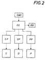
- control device CC which controls the machine control C of the cutting machine 2, the station control D of the take-off station 3 and the station control P of the loading station 4 for the display device 42 according to a suitable control program.
- the control program takes into account the correspondingly read in data of the composite workpiece to be produced, the blanks required for this, their size, position, arrangement and laying sequence and thus coordinates the functions of the cutting machine, removal station and insertion station in a rational manner.
- the blanks Z required for producing a workpiece are continuously cut out of a strip B in the reverse order of insertion into the insert mold and the strip is wound onto the storage roll 6.
- this storage roll 6 is brought into the take-off station 3 and this tape B is cut step by step via the control device to cut to size, so that the cuts are offered to the worker at the removal edge 34 in the correct order of insertion.
- This worker therefore only needs to take these blanks one after the other and insert them into the insertion mold 41, where the insertion point is already correctly indicated by the display device 42.
- the program with the data about the composite workpieces is read into the control device CC, for example via a CAD system, which control device then the respective control programs CP for the cutting machines 2, DP for the take-off station 3 and PP for the insertion station 4 created and controls these programs according to the respective machine and system controls C, D, P.
- Various program-specific data can be printed out or processed in another way via an additional output OD.
Landscapes
- Engineering & Computer Science (AREA)
- Chemical & Material Sciences (AREA)
- Composite Materials (AREA)
- Mechanical Engineering (AREA)
- Robotics (AREA)
- Textile Engineering (AREA)
- Folding Of Thin Sheet-Like Materials, Special Discharging Devices, And Others (AREA)
Applications Claiming Priority (2)
| Application Number | Priority Date | Filing Date | Title |
|---|---|---|---|
| AT328/94 | 1994-02-18 | ||
| AT0032894A AT401634B (de) | 1994-02-18 | 1994-02-18 | Verfahren und vorrichtung zum herstellen eines verbundwerkstückes |
Publications (1)
| Publication Number | Publication Date |
|---|---|
| EP0668146A1 true EP0668146A1 (fr) | 1995-08-23 |
Family
ID=3487664
Family Applications (1)
| Application Number | Title | Priority Date | Filing Date |
|---|---|---|---|
| EP95890029A Withdrawn EP0668146A1 (fr) | 1994-02-18 | 1995-02-07 | Procédé et dispositif pour la fabrication d'un article composite |
Country Status (2)
| Country | Link |
|---|---|
| EP (1) | EP0668146A1 (fr) |
| AT (1) | AT401634B (fr) |
Cited By (2)
| Publication number | Priority date | Publication date | Assignee | Title |
|---|---|---|---|---|
| EP3112137A1 (fr) * | 2015-06-23 | 2017-01-04 | The Boeing Company | Procédé et appareil de formation de raidisseurs profilés |
| EP3153308A1 (fr) * | 2015-10-07 | 2017-04-12 | Chaei Hsin Enterprise Co., Ltd. | Appareil de moulage par compression |
Families Citing this family (1)
| Publication number | Priority date | Publication date | Assignee | Title |
|---|---|---|---|---|
| CN113352533B (zh) * | 2021-04-25 | 2023-06-23 | 佛山市蕾兹家具有限公司 | 一种脱模前修剪乳胶床垫脱模方法 |
Citations (4)
| Publication number | Priority date | Publication date | Assignee | Title |
|---|---|---|---|---|
| EP0128826A1 (fr) * | 1983-06-08 | 1984-12-19 | Aerospatiale Societe Nationale Industrielle | Système intégré de drapage assisté pour la réalisation de pièces en matériaux composites |
| AT393983B (de) * | 1988-10-04 | 1992-01-10 | Gfm Holding Ag | Schneidanlage zum ausschneiden von zuschnitten aus bandfoermigem ausgangsmaterial, insbesondere von ein- oder beidseitig folienbedeckten prepregs |
| EP0470901A1 (fr) * | 1990-08-08 | 1992-02-12 | AEROSPATIALE Société Nationale Industrielle | Appareillage d'aide au drapage manuel de pièces en matériaux composites |
| DE4130269A1 (de) * | 1990-09-13 | 1992-03-19 | Toshiba Machine Co Ltd | Verfahren und vorrichtung zum herstellen laminierter prepreg-teile |
Family Cites Families (6)
| Publication number | Priority date | Publication date | Assignee | Title |
|---|---|---|---|---|
| GB2121347B (en) * | 1981-06-30 | 1985-11-20 | Boeing Co | Method of manufacturing a preform from fiber reinforced composite material |
| US4752352A (en) * | 1986-06-06 | 1988-06-21 | Michael Feygin | Apparatus and method for forming an integral object from laminations |
| ATE102095T1 (de) * | 1986-06-06 | 1994-03-15 | Michael Feygin | Vorrichtung und verfahren zur herstellung eines verbundkoerpers aus schichtmaterial. |
| DE3711470A1 (de) * | 1987-04-04 | 1988-10-27 | Fraunhofer Ges Forschung | Verfahren zum herstellen eines dreidimensionalen modells |
| FR2638999B1 (fr) * | 1988-11-15 | 1995-02-17 | Musset Claude | Procede de fabrication de maquette et dispositif de decoupe automatique d'elements pour cette fabrication |
| WO1991012957A1 (fr) * | 1990-02-28 | 1991-09-05 | Sparx Ab | Dispositif de fabrication d'objets tridimensionnels |
-
1994
- 1994-02-18 AT AT0032894A patent/AT401634B/de not_active IP Right Cessation
-
1995
- 1995-02-07 EP EP95890029A patent/EP0668146A1/fr not_active Withdrawn
Patent Citations (4)
| Publication number | Priority date | Publication date | Assignee | Title |
|---|---|---|---|---|
| EP0128826A1 (fr) * | 1983-06-08 | 1984-12-19 | Aerospatiale Societe Nationale Industrielle | Système intégré de drapage assisté pour la réalisation de pièces en matériaux composites |
| AT393983B (de) * | 1988-10-04 | 1992-01-10 | Gfm Holding Ag | Schneidanlage zum ausschneiden von zuschnitten aus bandfoermigem ausgangsmaterial, insbesondere von ein- oder beidseitig folienbedeckten prepregs |
| EP0470901A1 (fr) * | 1990-08-08 | 1992-02-12 | AEROSPATIALE Société Nationale Industrielle | Appareillage d'aide au drapage manuel de pièces en matériaux composites |
| DE4130269A1 (de) * | 1990-09-13 | 1992-03-19 | Toshiba Machine Co Ltd | Verfahren und vorrichtung zum herstellen laminierter prepreg-teile |
Cited By (4)
| Publication number | Priority date | Publication date | Assignee | Title |
|---|---|---|---|---|
| EP3112137A1 (fr) * | 2015-06-23 | 2017-01-04 | The Boeing Company | Procédé et appareil de formation de raidisseurs profilés |
| JP2017052267A (ja) * | 2015-06-23 | 2017-03-16 | ザ・ボーイング・カンパニーThe Boeing Company | 起伏のある補強材を形成するための方法及び装置 |
| US11072157B2 (en) | 2015-06-23 | 2021-07-27 | The Boeing Company | Method and apparatus for forming contoured stiffeners |
| EP3153308A1 (fr) * | 2015-10-07 | 2017-04-12 | Chaei Hsin Enterprise Co., Ltd. | Appareil de moulage par compression |
Also Published As
| Publication number | Publication date |
|---|---|
| AT401634B (de) | 1996-10-25 |
| ATA32894A (de) | 1996-03-15 |
Similar Documents
| Publication | Publication Date | Title |
|---|---|---|
| DE69512687T2 (de) | Komponententrägerband | |
| DE4130269C2 (de) | Verfahren und Vorrichtung zum Herstellen laminierter Prepreg-Teile | |
| EP1263567B1 (fr) | Procede et dispositif permettant d'appliquer des decoupes de films auto-adhesives, notamment sur des pieces de carrosserie de vehicules | |
| EP1452474B1 (fr) | Procédé et dispositif pour la fabrication mécanique d'un enroulement de câble sans support | |
| DE69406514T2 (de) | Verfahren und Vorrichtung zur Herstellung eines geschnittenen kunstoffimprägnierten Bandes | |
| DE19606395C1 (de) | Verfahren und Vorrichtung zum Applizieren einer Folie auf eine Oberfläche | |
| DE19809516B4 (de) | Vorrichtung und Verfahren zum automatischen Wechseln von Folienrollen | |
| DE10342658A1 (de) | Verfahren zum Auftragen eines Klebebandes | |
| DE3032016C2 (de) | Verfahren und Vorrichtung zur Herstellung von mit doppellagigen Einstecktaschen aus Folienmaterial beklebten Blättern | |
| DE202007013417U1 (de) | Vorrichtung zur Herstellung langer, konfektionierter, elektrischer Leitungen in einem CrimpCenter | |
| AT401634B (de) | Verfahren und vorrichtung zum herstellen eines verbundwerkstückes | |
| DE3130121C2 (de) | Vorrichtung zum Anbringen von oberen Begrenzungsteilen an einem Reißverschlußband | |
| DE2650457B2 (de) | Vorrichtung zum Laden von Magnetbandkassetten mit Magnetband | |
| EP0509419B1 (fr) | Procédé et dispositif pour séparer des découps de feuilles laminées | |
| DE69312823T2 (de) | Automatische Wickelmaschine für bandartige Produkte | |
| EP0446322B1 (fr) | Installation de fabrication de rouleaux de treillis | |
| EP3722071B1 (fr) | Dispositif d'application d'un film de protection perforé sur une surface d'un composant | |
| EP0593410B1 (fr) | Procédé et dispositif pour poser par bandes un matériau en forme de ruban | |
| DE4026144A1 (de) | Verfahren zum herstellen eines kontinuums von aufklebern | |
| DE2533708A1 (de) | Verfahren und vorrichtung zur prozessverfolgung | |
| EP2853377B1 (fr) | Système de changement pour machine d'enduction ainsi que procédé | |
| EP0368027B1 (fr) | Méthode et dispositif de fabrication de produits stratifiés en partant de bandes autocollantes | |
| DE19837036A1 (de) | Stegkantenaggregat | |
| AT527225B1 (de) | Vorrichtung und Verfahren zur Herstellung eines Ringes | |
| EP2791450B1 (fr) | Procédé et dispositif de changement d'écarteurs |
Legal Events
| Date | Code | Title | Description |
|---|---|---|---|
| PUAI | Public reference made under article 153(3) epc to a published international application that has entered the european phase |
Free format text: ORIGINAL CODE: 0009012 |
|
| AK | Designated contracting states |
Kind code of ref document: A1 Designated state(s): AT DE FR GB IT SE |
|
| 17P | Request for examination filed |
Effective date: 19951218 |
|
| 17Q | First examination report despatched |
Effective date: 19960314 |
|
| GRAG | Despatch of communication of intention to grant |
Free format text: ORIGINAL CODE: EPIDOS AGRA |
|
| GRAH | Despatch of communication of intention to grant a patent |
Free format text: ORIGINAL CODE: EPIDOS IGRA |
|
| STAA | Information on the status of an ep patent application or granted ep patent |
Free format text: STATUS: THE APPLICATION IS DEEMED TO BE WITHDRAWN |
|
| 18D | Application deemed to be withdrawn |
Effective date: 19970204 |