EP0668237B1 - Procédé pour la manutention d'une charge à l'aide d'une grue - Google Patents
Procédé pour la manutention d'une charge à l'aide d'une grue Download PDFInfo
- Publication number
- EP0668237B1 EP0668237B1 EP95101850A EP95101850A EP0668237B1 EP 0668237 B1 EP0668237 B1 EP 0668237B1 EP 95101850 A EP95101850 A EP 95101850A EP 95101850 A EP95101850 A EP 95101850A EP 0668237 B1 EP0668237 B1 EP 0668237B1
- Authority
- EP
- European Patent Office
- Prior art keywords
- load
- target
- actual position
- crane
- actual
- Prior art date
- Legal status (The legal status is an assumption and is not a legal conclusion. Google has not performed a legal analysis and makes no representation as to the accuracy of the status listed.)
- Expired - Lifetime
Links
Images


Classifications
-
- B—PERFORMING OPERATIONS; TRANSPORTING
- B66—HOISTING; LIFTING; HAULING
- B66C—CRANES; LOAD-ENGAGING ELEMENTS OR DEVICES FOR CRANES, CAPSTANS, WINCHES, OR TACKLES
- B66C13/00—Other constructional features or details
- B66C13/18—Control systems or devices
- B66C13/48—Automatic control of crane drives for producing a single or repeated working cycle; Program control
-
- B—PERFORMING OPERATIONS; TRANSPORTING
- B66—HOISTING; LIFTING; HAULING
- B66C—CRANES; LOAD-ENGAGING ELEMENTS OR DEVICES FOR CRANES, CAPSTANS, WINCHES, OR TACKLES
- B66C13/00—Other constructional features or details
- B66C13/04—Auxiliary devices for controlling movements of suspended loads, or preventing cable slack
- B66C13/06—Auxiliary devices for controlling movements of suspended loads, or preventing cable slack for minimising or preventing longitudinal or transverse swinging of loads
- B66C13/063—Auxiliary devices for controlling movements of suspended loads, or preventing cable slack for minimising or preventing longitudinal or transverse swinging of loads electrical
-
- B—PERFORMING OPERATIONS; TRANSPORTING
- B66—HOISTING; LIFTING; HAULING
- B66C—CRANES; LOAD-ENGAGING ELEMENTS OR DEVICES FOR CRANES, CAPSTANS, WINCHES, OR TACKLES
- B66C13/00—Other constructional features or details
- B66C13/18—Control systems or devices
- B66C13/46—Position indicators for suspended loads or for crane elements
Definitions
- the invention relates to a method for conveying a load by means of a crane according to the preamble of claim 1.
- Cranes e.g. Container cranes serve to carry loads on one predetermined place to record them over a known Promote route and at a specified destination, for example a target container. This results in practice the problem that for the promotion of the load in Direction towards the target is not the exact actual position of the target is known. Instead, a target position of the target is known which, for example, by the middle of a given Target area can be defined.
- a method according to the preamble of claim 1 is known from the DE magazine "Funding and lifting", Volume 42 (1992), No. 11, Pages 890 to 892.
- This procedure means the actual position of the load detected and fed a path control, which is dependent on the difference between the detected actual position of the load and a predetermined target position of the target controls the load towards the target.
- This method is, however, for a precise positioning of the load on Cannot use target.
- the object of the invention is the known method to be modified in such a way that precise positioning the load on a target is possible.
- This object is achieved in that in The actual position of the target by means of a sensor device Load and the actual position of the target relative to each other be fed and the path control, which is dependent the difference between the actual position of the load and the actual position of the target on the positioning of the load controls the target, taking as the load approaches the target between the different, fed the route control Position sizes is blended.
- the Actual position of the load preferably by means of a path measuring device that constantly measures the position of a cat, to which the load hangs.
- a path measuring device that constantly measures the position of a cat, to which the load hangs.
- the measuring device it can is, for example, a displacement sensor or a laser distance measuring device act that the distance between the cat and a fixed reference position.
- the measurement of the pendulum angle the load can be, for example, by an optical scanning device, such as B. a camera or preferably laser range finders, done on the cat is arranged and in a scanning angle range open downwards scans the outer edges of the load.
- the pendulum angle of the load is measured that in the area of the load a marking with reflective Surface is arranged that on the crane the marking directed lighting device and a line camera also pointed at the marking with a image sensor line aligned along the pendulum direction is arranged and that downstream of the image sensor line Evaluation device from the signal of the image sensor line one corresponding to the current position of the marking Output signal is generated.
- This measuring principle can alone or together with the measurement by the mentioned Laser distance profile measuring devices can be used.
- the measurement of the pendulum angle with the help of laser distance profile measuring devices and / or line scan camera is in EP-A-0 596 330 explained in detail.
- the cross-fading is preferably carried out by the sensor device triggered.
- This can be an optical scanner comprise, which is arranged in the region of the crane and in a scanning angle range open downwards Outer edges of the load and the underlying environment of the Load scans, which is the optical scanner around a camera or preferably around laser distance profile measuring devices acts.
- the transition between the different position values supplied to the position control takes place when the sensor device simultaneously the load and the goal are grasped. After the transition then depending on the difference between that of the Sensor device determined actual positions of the load and the The goal is to position the load precisely on the target regulated.
- Scanning device on the crane can also in the Be arranged in the area of the load and in an open downward Scanning angle range scan the area around the load.
- the crossfade is triggered as soon as that Target is detected by the scanner. Because the scanner is located in the area of the load, it detects automatically the position of the target relative to each current position of the load.
- Such in the field of Load arranged scanner is in the European Patent application 93 10 9943.6 explained in detail.
- FIG. 1 schematically shows a trolley 1 which can be moved on a jib 2 of a container crane, not shown here, and on which a load 3, here a container, hangs.
- this load 3 is to be picked up at the starting position x 0 and conveyed over a certain distance to a target position x Z and placed there on a target container 4.
- the actual actual position x Z of target 4 is not known, but only a target position x Z *, which is defined, for example, as the center of a target area ⁇ x Z *.
- the actual position x L of the load 3 is continuously measured and compared with the target position x Z * of the target 4.
- the actual position x K of the trolley 1 and the current pendulum angle ⁇ L of the load 3 are continuously measured and the actual position x L of the load 3 is determined from them.
- the trolley 1 is moved in the direction of the target 4 by a path control.
- the cat 1 is moved along the boom 2, for example, with the travel speed denoted by v K , so that pendulum movements of the load 3 are largely avoided, in particular when the target 4 is reached. If the load 3 is in the vicinity of the target 4, the actual position x L of the load 3 and the actual position x Z of the target 4 relative to one another are detected by means of a sensor device, and the deposition of the load as a function thereof 3 controlled on the target 4.
- a laser distance measuring device 8 is arranged on it, which measures in the direction of travel x of the cat 1 to a fixed reference position 9 in the form of a reflection mark.
- two scanning devices in the form of laser distance profile measuring devices 10 and 11 are arranged above the two outer edges 12 and 13 of the load-bearing frame 7 which run transversely to the direction of travel x of the cat 1.
- Each of the two laser distance profile measuring devices 10 and 11 generates a laser beam 14 and 15, respectively, which is deflected in a scanning angle range which is open along the pendulum direction x and the outer edge 12 or 13 perpendicular to the respective laser distance profile measuring device 10 or 11.
- the current pendulum angle Last L of the load 3 is determined with the aid of the two laser distance profile measuring devices 10 and 11 and together with that by the laser Distance measuring device 8 uses the actual position x K of the cat 1 to determine the actual position x L of the load 3.
- the actual position x L of the load 3 thus obtained is compared with the target position x Z * of the target 4 and the trolley 1 is moved as a function of the comparison result.
- the laser beams 14 and 15 also detect areas of the target container 4 when the load 3 approaches the target container 4. If the target container 4 is identified in this way, the path control for the trolley 1 is no longer dependent on the means of the laser distance measuring device 8 and the two laser distance profile measuring devices 10 and 11 determine the actual position x L of the load 3 and the target position x Z * of the target 4, but instead the position deviation between the load determined by the two laser distance profile measuring devices 10 and 11 3 and the target container 4 used for further displacement control of the trolley 1. As long as the load 3 is not positioned exactly above the target container 4, the laser beams 14 and 15 also detect areas of the target container 4. As soon as both laser beams 14 and 15 no longer strike the target container 4, the load 3 is positioned directly above the target container 4 and can be lowered onto this.
- the optimal position of the two laser range finders 10 and 11 in the x direction is not immediately over the respective outer edges 12 and 13 of the load suspension frame 7, but somewhat outside of it, so that below the Outer edges 12 and 13 none for laser beams 14 and 15 inaccessible blind spot.
- the two laser range finders 10 and 11 are also the two laser range finders 10 and 11 with their Scanning angle ranges 14 and 15 transverse to the x direction, that is in z-direction offset. This makes it possible, except Pendulum movements in the x direction also include the pendulum To measure the load, which is expressed in the fact that the laser beams 14 and 15 measured x coordinates of the outer edges Change 12 and 13 differently.
- the Outer edges 12 and 13 are the safest in the area of all Scan containers with the same corner fittings of container 4. Because containers also have different lengths can, are the two laser range finders 10 and 11 arranged in the z-direction on the trolley 1.
- a mark 16 is attached to the load-bearing frame 7, which from one at rest of the load 3 vertically above this headlights 17 held on the cat 1 is illuminated, the light reflected by the marker 16 from a arranged immediately next to or in the headlight 15 Line camera 18 is detected.
- the mark 16 consists of a rectangular, with an edge side parallel to Pendulum direction x aligned reflective surface, which is surrounded by a non-reflecting surface 19.
- the reflective surface 16 consists of a plurality of triple reflector elements, not shown here, on them reflect incident light in the direction from which it has come.
- the Line camera 16 is arranged on the trolley 1 in such a way that their scanning plane 20 marks 16 along the pendulum direction x cuts.
- To record the position of the marking 16 becomes the serial output signal of the line camera 18 after the occurrence of the two brightness changes with each searched the greatest contrast and in this way the edges of the reflecting edges running transversely to the scanning direction 20 Area 16 detected. From the middle between the the position is determined for both detected brightness changes the middle of the mark 16 determined and as an output signal the line camera 18 provided.
- the difference to the two laser distance profile measuring devices 10 and 11 result considerably in the measurements with the line camera 18 shorter measuring times, what for the regulation of load oscillations and an advantage for load positioning control is.
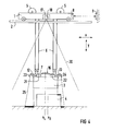
- no laser distance profile measuring devices are provided on the trolley 1, but instead two, but preferably four, laser distance profile measuring devices 21 and 22 are arranged on the load-bearing frame 7.
- Each of the laser distance profile measuring devices 21, 22 each generates a laser beam which is deflected in a predetermined scanning angle range.
- devices 23, 24 for beam deflection are each arranged in such a way that the laser distance profile measuring device, for. B.
- FIG 4 differs FIG 4 not of that of FIG 2, so that the same parts are provided with the same reference numerals.
- the actual position x L of the load 3 is continuously measured by means of the laser distance measuring device 8 and the two laser distance profile measuring devices 10 and 11 when the load 3 is conveyed from the starting position x 0 to the destination 4.
- the difference between the measured actual position x L of the load 3 and the predetermined target position x Z * of the target 4 is formed in a subtracting node 26 and is fed via a controllable switchover device 27 to a path control 28 which, depending on the determined difference, drives a drive 29 for moving the trolley 1 controls.
- the switching device 27 is activated, so that now the difference between the actual position x and 11 measured by the two laser distance profile measuring devices 10 and 11 L of the load 3 and the actual position x Z of the target 4 of the path control 28 is supplied. So that there are no abrupt changes in the control process during the switchover, the input variables supplied immediately before and immediately after the switchover of the position control 28 are temporarily stored in a memory 30 and subtracted from one another. The difference obtained in this way is fed to the input of the displacement control 28 via a device 31 and is added there with a negative sign to the input signal for the displacement control 28 coming from the switching device 27.
- the input variable for the position control 28 does not change immediately after the switchover.
- the difference formed in the storage device 30 is reduced within a predetermined time interval to the value zero, so that after this time interval the input variable x Z -x L is fed to the position control 28. In this way, there is a crossfade between the input variables x Z * -x L and x Z -x L.
Landscapes
- Engineering & Computer Science (AREA)
- Mechanical Engineering (AREA)
- Automation & Control Theory (AREA)
- Control And Safety Of Cranes (AREA)
Claims (7)
- Procédé pour la manutention d'une charge (3) à l'aide d'un pont roulant, la charge (3) étant prise à une position (x0) de départ et transportée sur un parcours horizontal jusqu'à une destination (4) où elle est déposée, la position (xL) effective de la charge (3) étant relevée au moyen d'un dispositif (8, 10, 11, 18) de relevé de déplacement et transmise à une régulation (28) de déplacement, qui commande le transport de la charge (3) vers la destination (4) en fonction de la différence entre la position (xL) effective relevée de la charge (3) et une position (xZ*) de consigne prescrite de la destination (4),
caractérisé en ce que, à proximité de la destination, on relève au moyen d'un dispositif (10, 11 ; 21, 22) de détection la position (xL) effective de la charge (3) et la position (xZ) effective de la destination (4) l'une par rapport à l'autre, et on les transmet à la régulation (28) de déplacement, qui commande le positionnement de la charge (3) à la destination (4) en fonction de la différence entre la position (xL) effective de la charge (3) et la position (xZ) effective de la destination (4), une fusion des grandeurs différentes de position transmises à la régulation (28) de déplacement étant effectuée lorsque la charge (3) s'approche de la destination (4). - Procédé suivant la revendication 1, caractérisé en ce que, lors du transport de la charge (3) vers la destination (4), on relève la position (xL) effective de la charge (3) au moyen d'un dispositif (8) de mesure de déplacement qui mesure en continu la position d'un chariot (1) auquel la charge (3) est suspendue.
- Procédé suivant la revendication 2, caractérisé en ce qu'on mesure en plus l'angle () de balancement de la charge (3), et on s'en sert conjointement avec la position (xK) mesurée du chariot (1) pour calculer la position (xL) effective de la charge (3).
- Procédé suivant la revendication 3, caractérisé en ce qu'un repère (16) à surface réfléchissante est disposé dans la région de la charge (3), en ce qu'un dispositif (17) d'éclairage dirigé sur le repère (16) est disposé sur le pont roulant, ainsi qu'une caméra (18) à balayage horizontal, également dirigée sur le repère (16) et dotée d'une ligne de détection d'image orientée le long de la direction (x) de balancement, et en ce que, dans un dispositif d'interprétation disposé à la suite de la ligne(18) de détection d'image, on produit à partir du signal de la ligne de détection d'image un signal de sortie correspondant à la position instantanée du repère (16).
- Procédé suivant l'une des revendications précédentes, caractérisé en ce que la fusion entre les grandeurs différentes de position transmises à la régulation (28) de déplacement est déclenchée par le dispositif (10, 11 ; 21, 22) de détection.
- Procédé suivant l'une des revendications précédentes, caractérisé en ce que le dispositif de détection comprend un dispositif (10, 11) de balayage optique qui est disposé dans la région du pont roulant et balaye, dans une plage (14, 15) d'angle de balayage ouverte vers le bas, les bords (12, 13) extérieurs de la charge (3) et l'environnement sous-jacent de la charge (3).
- Procédé suivant l'une des revendications 1 à 5, caractérisé en ce que le dispositif de détection comprend un dispositif (21, 22) de balayage optique, qui est disposé dans la région de la charge (3) et balaye l'environnement de la charge (3) dans une plage (25) d'angle de balayage ouverte vers le bas.
Applications Claiming Priority (2)
| Application Number | Priority Date | Filing Date | Title |
|---|---|---|---|
| DE4405683A DE4405683A1 (de) | 1994-02-22 | 1994-02-22 | Verfahren zur Förderung einer Last mittels eines Krans |
| DE4405683 | 1994-02-22 |
Publications (2)
| Publication Number | Publication Date |
|---|---|
| EP0668237A1 EP0668237A1 (fr) | 1995-08-23 |
| EP0668237B1 true EP0668237B1 (fr) | 1999-09-15 |
Family
ID=6510901
Family Applications (1)
| Application Number | Title | Priority Date | Filing Date |
|---|---|---|---|
| EP95101850A Expired - Lifetime EP0668237B1 (fr) | 1994-02-22 | 1995-02-10 | Procédé pour la manutention d'une charge à l'aide d'une grue |
Country Status (2)
| Country | Link |
|---|---|
| EP (1) | EP0668237B1 (fr) |
| DE (2) | DE4405683A1 (fr) |
Families Citing this family (16)
| Publication number | Priority date | Publication date | Assignee | Title |
|---|---|---|---|---|
| DE19630187C2 (de) * | 1996-07-26 | 2001-03-22 | Noell Stahl Und Maschb Gmbh | Einrichtung zum automatischen Positionieren eines von zwei gegeneinander beweglichen Objekten |
| JPH10139369A (ja) * | 1996-11-08 | 1998-05-26 | Mitsubishi Heavy Ind Ltd | 吊荷の振れ止め制御装置 |
| DE19709381A1 (de) * | 1997-03-07 | 1998-09-10 | Gerhard Prof Dr Ing Wagner | Verfahren zur Unterdrückung von Pendelbewegungen einer zum Transport an einer Laufkatze hängenden Last im Zielort |
| DE19803202A1 (de) * | 1998-01-28 | 1999-07-29 | Tax Technical Consultancy Gmbh | Zieldetektionseinrichtung |
| DE19836103A1 (de) * | 1998-08-10 | 2000-02-24 | Siemens Ag | Vorrichtung und Verfahren zur zweidimensionalen Bestimmung von Lastpendelungen und/oder -rotationen an einem Kran |
| DE19841570C2 (de) * | 1998-09-11 | 2001-04-12 | Telerob Ges Fuer Fernhantierun | Kaikran zum Be- und Entladen von Containern |
| JP3785061B2 (ja) * | 2000-10-27 | 2006-06-14 | 三菱重工業株式会社 | 荷役クレーンにおけるコンテナ位置検知方法及び装置並びにコンテナ着床、段積制御方法 |
| DE10103636A1 (de) * | 2001-01-27 | 2002-08-22 | Noell Crane Sys Gmbh | Drehzalgesteuerter Fahrantrieb |
| DE10233943A1 (de) * | 2002-07-25 | 2004-02-19 | Siemens Ag | Containerkran |
| DE102004018021A1 (de) * | 2004-04-14 | 2005-11-03 | Bosch Rexroth Ag | Lasthebevorrichtung |
| FI117835B (fi) | 2005-06-22 | 2007-03-15 | Sime Oy | Paikoitusmenetelmä |
| CN105800471B (zh) * | 2016-04-22 | 2018-01-16 | 长沙市致能电子科技有限公司 | 一种全自动天车控制系统、方法以及一种全自动天车 |
| CN109455619B (zh) * | 2018-12-30 | 2020-09-11 | 三一海洋重工有限公司 | 集装箱姿态的定位方法、装置及吊具控制器 |
| CN113428790B (zh) * | 2020-03-23 | 2023-07-04 | 杭州海康威视系统技术有限公司 | 集装箱信息识别方法、装置、监控设备及系统 |
| FI130945B1 (fi) | 2021-05-10 | 2024-06-11 | Konecranes Global Oy | Kontinhallintalaitteiston position määrittäminen |
| KR20240031731A (ko) * | 2022-09-01 | 2024-03-08 | 삼성전자주식회사 | 천장 저장 시스템 및 그 제어 방법 |
Family Cites Families (11)
| Publication number | Priority date | Publication date | Assignee | Title |
|---|---|---|---|---|
| SE361869B (fr) * | 1972-04-14 | 1973-11-19 | Asea Ab | |
| US4172685A (en) * | 1976-10-22 | 1979-10-30 | Hitachi, Ltd. | Method and apparatus for automatic operation of container crane |
| DE3445830A1 (de) * | 1984-12-15 | 1986-06-19 | Dürr Anlagenbau GmbH, 7000 Stuttgart | Foerderanlage mit positioniervorrichtung |
| DE3735145A1 (de) * | 1987-10-16 | 1989-04-27 | Siemens Ag | Einrichtung zum rechnergesteuerten positionieren eines hebezeugs |
| DE3816988A1 (de) * | 1988-05-18 | 1989-11-30 | Tax Ingenieurgesellschaft Mbh | Containerkrananlage |
| DE3933527A1 (de) * | 1989-10-04 | 1991-04-18 | Mannesmann Ag | Verfahren zur daempfung von lastpendelschwingungen |
| DE4005066C2 (de) * | 1990-02-14 | 1995-12-07 | Bremer Lagerhaus Ges | Verfahren zum Steuern des Be- und Entladens eines Container-Fahrzeuges sowie Verwendung eines Vertikal-Entfernungsmessers an einem Spreader |
| SE502609C2 (sv) * | 1990-03-28 | 1995-11-20 | Asea Brown Boveri | Förflyttning av gods med containerkranar |
| SE470018B (sv) * | 1991-05-06 | 1993-10-25 | Bromma Conquip Ab | Optiskt avkännings- och styrningssystem |
| EP0596330B1 (fr) * | 1992-11-03 | 1997-05-28 | Siemens Aktiengesellschaft | Arrangement pour mesurer les oscillations d'une charge de grue |
| IL104723A0 (en) * | 1993-02-14 | 1993-06-10 | Lepek Alexander | Crane system including distance measurement and collision control |
-
1994
- 1994-02-22 DE DE4405683A patent/DE4405683A1/de not_active Withdrawn
-
1995
- 1995-02-10 DE DE59506816T patent/DE59506816D1/de not_active Expired - Fee Related
- 1995-02-10 EP EP95101850A patent/EP0668237B1/fr not_active Expired - Lifetime
Also Published As
| Publication number | Publication date |
|---|---|
| EP0668237A1 (fr) | 1995-08-23 |
| DE59506816D1 (de) | 1999-10-21 |
| DE4405683A1 (de) | 1995-08-24 |
Similar Documents
| Publication | Publication Date | Title |
|---|---|---|
| EP0596330B1 (fr) | Arrangement pour mesurer les oscillations d'une charge de grue | |
| EP2910512B1 (fr) | Procédé d'étalonnage de scanners laser sur une grue de manutention de conteneurs | |
| EP0656868B1 (fr) | Procede et dispositif de commande d'un pont dechargeur pour conteneurs | |
| EP0342655B1 (fr) | Installation de grue pour conteneur | |
| DE19713826B4 (de) | Radarvorrichtung | |
| EP0668237A1 (fr) | Procédé pour la manutention d'une charge à l'aide d'une grue | |
| DE19519741A1 (de) | Sensorik für einen Kran, insbesondere einen schienengebundenen Stapelkran oder Brückenkran | |
| AT504557B1 (de) | Verfahren zum navigieren eines transportmittels für waren | |
| DE20022617U1 (de) | Vorrichtung zur Erfassung der Position von einem Fahrzeug in einem vorgegebenen Bereich, insbesondere einer Lagereinrichtung, und zugehörige Bezugsmarkierung | |
| EP0668236B1 (fr) | Arrangement pour positioner des charges de grue | |
| DE69623336T2 (de) | Verfahren zur bestimmung von positionen von gegenständen und gerät zur generierung eines satzes von gegenständen mit bekannten positionen | |
| DE10323641A1 (de) | Bewegliche Sensoreinrichtung am Lastmittel eines Gabelstaplers | |
| EP0559850A1 (fr) | Procede de mesurage de voies de chemin de fer. | |
| DE4190587C2 (de) | Transport und Positionierung von Gütern mittels Containerkränen | |
| DE2316810A1 (de) | Anordnung bei kraenen zur bestimmung der abweichung des lastbefestigungsorgans von einer definierten lotrechten linie | |
| WO2004041707A1 (fr) | Grue de transport de conteneurs | |
| DE102007021693A1 (de) | Hilfssystem zur Lagebestimmung eines Fahrzeugs | |
| DE3445830A1 (de) | Foerderanlage mit positioniervorrichtung | |
| WO2009043789A1 (fr) | Procédé de calibrage d'un dispositif de détection et dispositif de détection | |
| DE202019102253U1 (de) | Vorrichtung zum Verifizieren von Lagergut-Positionen in intralogistischen Lagersystemen | |
| EP0822158B1 (fr) | Procédé pour positionner automatiquement un objet mobile par rapport à un autre objet mobile | |
| EP1169673B1 (fr) | Procede de determination de la position d'un vehicule | |
| DE19841570C2 (de) | Kaikran zum Be- und Entladen von Containern | |
| DE10202399A1 (de) | Einrichtung und Verfahren zur Positionierung von Transportfahrzeugen | |
| DE4403898A1 (de) | Hebezeug |
Legal Events
| Date | Code | Title | Description |
|---|---|---|---|
| PUAI | Public reference made under article 153(3) epc to a published international application that has entered the european phase |
Free format text: ORIGINAL CODE: 0009012 |
|
| AK | Designated contracting states |
Kind code of ref document: A1 Designated state(s): BE DE IT NL SE |
|
| 17P | Request for examination filed |
Effective date: 19960119 |
|
| 17Q | First examination report despatched |
Effective date: 19980624 |
|
| GRAG | Despatch of communication of intention to grant |
Free format text: ORIGINAL CODE: EPIDOS AGRA |
|
| GRAG | Despatch of communication of intention to grant |
Free format text: ORIGINAL CODE: EPIDOS AGRA |
|
| GRAH | Despatch of communication of intention to grant a patent |
Free format text: ORIGINAL CODE: EPIDOS IGRA |
|
| GRAH | Despatch of communication of intention to grant a patent |
Free format text: ORIGINAL CODE: EPIDOS IGRA |
|
| GRAA | (expected) grant |
Free format text: ORIGINAL CODE: 0009210 |
|
| AK | Designated contracting states |
Kind code of ref document: B1 Designated state(s): BE DE IT NL SE |
|
| PG25 | Lapsed in a contracting state [announced via postgrant information from national office to epo] |
Ref country code: SE Free format text: THE PATENT HAS BEEN ANNULLED BY A DECISION OF A NATIONAL AUTHORITY Effective date: 19990915 Ref country code: IT Free format text: LAPSE BECAUSE OF FAILURE TO SUBMIT A TRANSLATION OF THE DESCRIPTION OR TO PAY THE FEE WITHIN THE PRE;WARNING: LAPSES OF ITALIAN PATENTS WITH EFFECTIVE DATE BEFORE 2007 MAY HAVE OCCURRED AT ANY TIME BEFORE 2007. THE CORRECT EFFECTIVE DATE MAY BE DIFFERENT FROM THE ONE RECORDED.SCRIBED TIME-LIMIT Effective date: 19990915 |
|
| REF | Corresponds to: |
Ref document number: 59506816 Country of ref document: DE Date of ref document: 19991021 |
|
| PGFP | Annual fee paid to national office [announced via postgrant information from national office to epo] |
Ref country code: BE Payment date: 20000218 Year of fee payment: 6 |
|
| PGFP | Annual fee paid to national office [announced via postgrant information from national office to epo] |
Ref country code: NL Payment date: 20000229 Year of fee payment: 6 |
|
| PLBE | No opposition filed within time limit |
Free format text: ORIGINAL CODE: 0009261 |
|
| STAA | Information on the status of an ep patent application or granted ep patent |
Free format text: STATUS: NO OPPOSITION FILED WITHIN TIME LIMIT |
|
| 26N | No opposition filed | ||
| PG25 | Lapsed in a contracting state [announced via postgrant information from national office to epo] |
Ref country code: DE Free format text: LAPSE BECAUSE OF NON-PAYMENT OF DUE FEES Effective date: 20001201 |
|
| PG25 | Lapsed in a contracting state [announced via postgrant information from national office to epo] |
Ref country code: BE Free format text: LAPSE BECAUSE OF NON-PAYMENT OF DUE FEES Effective date: 20010228 |
|
| BERE | Be: lapsed |
Owner name: SIEMENS A.G. Effective date: 20010228 |
|
| PG25 | Lapsed in a contracting state [announced via postgrant information from national office to epo] |
Ref country code: NL Free format text: LAPSE BECAUSE OF NON-PAYMENT OF DUE FEES Effective date: 20010901 |
|
| NLV4 | Nl: lapsed or anulled due to non-payment of the annual fee |
Effective date: 20010901 |