EP0668341A1 - FCC-Verfahren mit Steigrohrreaktor-Auslösungszone mit Abtrennungszone für suspendierte Katalysatoren - Google Patents
FCC-Verfahren mit Steigrohrreaktor-Auslösungszone mit Abtrennungszone für suspendierte Katalysatoren Download PDFInfo
- Publication number
- EP0668341A1 EP0668341A1 EP94301210A EP94301210A EP0668341A1 EP 0668341 A1 EP0668341 A1 EP 0668341A1 EP 94301210 A EP94301210 A EP 94301210A EP 94301210 A EP94301210 A EP 94301210A EP 0668341 A1 EP0668341 A1 EP 0668341A1
- Authority
- EP
- European Patent Office
- Prior art keywords
- riser
- catalyst
- zone
- stripping
- reactor
- Prior art date
- Legal status (The legal status is an assumption and is not a legal conclusion. Google has not performed a legal analysis and makes no representation as to the accuracy of the status listed.)
- Granted
Links
- 239000003054 catalyst Substances 0.000 title claims abstract description 215
- 238000000034 method Methods 0.000 title claims abstract description 28
- 230000008569 process Effects 0.000 title claims abstract description 24
- 238000000926 separation method Methods 0.000 title abstract description 21
- 239000002245 particle Substances 0.000 claims description 52
- 239000000571 coke Substances 0.000 claims description 23
- 239000000203 mixture Substances 0.000 claims description 17
- 230000008929 regeneration Effects 0.000 claims description 15
- 238000011069 regeneration method Methods 0.000 claims description 15
- 238000004523 catalytic cracking Methods 0.000 claims description 8
- 239000000725 suspension Substances 0.000 claims description 5
- 238000012546 transfer Methods 0.000 claims description 5
- 238000004891 communication Methods 0.000 claims description 4
- 230000008021 deposition Effects 0.000 claims description 4
- 238000013022 venting Methods 0.000 abstract description 2
- 239000007789 gas Substances 0.000 description 34
- 150000002430 hydrocarbons Chemical class 0.000 description 30
- 229930195733 hydrocarbon Natural products 0.000 description 29
- 239000000047 product Substances 0.000 description 25
- 238000006243 chemical reaction Methods 0.000 description 18
- JTJMJGYZQZDUJJ-UHFFFAOYSA-N phencyclidine Chemical class C1CCCCN1C1(C=2C=CC=CC=2)CCCCC1 JTJMJGYZQZDUJJ-UHFFFAOYSA-N 0.000 description 16
- 239000004215 Carbon black (E152) Substances 0.000 description 15
- 238000005336 cracking Methods 0.000 description 11
- 239000003921 oil Substances 0.000 description 10
- 239000000463 material Substances 0.000 description 7
- 230000008901 benefit Effects 0.000 description 4
- 239000012530 fluid Substances 0.000 description 4
- 230000003197 catalytic effect Effects 0.000 description 3
- 230000008859 change Effects 0.000 description 3
- 230000007423 decrease Effects 0.000 description 3
- 230000001105 regulatory effect Effects 0.000 description 3
- UGFAIRIUMAVXCW-UHFFFAOYSA-N Carbon monoxide Chemical compound [O+]#[C-] UGFAIRIUMAVXCW-UHFFFAOYSA-N 0.000 description 2
- QVGXLLKOCUKJST-UHFFFAOYSA-N atomic oxygen Chemical compound [O] QVGXLLKOCUKJST-UHFFFAOYSA-N 0.000 description 2
- 238000002485 combustion reaction Methods 0.000 description 2
- 238000009833 condensation Methods 0.000 description 2
- 230000005494 condensation Effects 0.000 description 2
- 238000001816 cooling Methods 0.000 description 2
- 230000008878 coupling Effects 0.000 description 2
- 238000010168 coupling process Methods 0.000 description 2
- 238000005859 coupling reaction Methods 0.000 description 2
- 238000013461 design Methods 0.000 description 2
- 238000009826 distribution Methods 0.000 description 2
- 239000003546 flue gas Substances 0.000 description 2
- 239000008246 gaseous mixture Substances 0.000 description 2
- 229910052751 metal Inorganic materials 0.000 description 2
- 239000002184 metal Substances 0.000 description 2
- 230000003647 oxidation Effects 0.000 description 2
- 238000007254 oxidation reaction Methods 0.000 description 2
- 229910052760 oxygen Inorganic materials 0.000 description 2
- 239000001301 oxygen Substances 0.000 description 2
- 238000004227 thermal cracking Methods 0.000 description 2
- OKTJSMMVPCPJKN-UHFFFAOYSA-N Carbon Chemical compound [C] OKTJSMMVPCPJKN-UHFFFAOYSA-N 0.000 description 1
- UFHFLCQGNIYNRP-UHFFFAOYSA-N Hydrogen Chemical compound [H][H] UFHFLCQGNIYNRP-UHFFFAOYSA-N 0.000 description 1
- 241000287181 Sturnus vulgaris Species 0.000 description 1
- NINIDFKCEFEMDL-UHFFFAOYSA-N Sulfur Chemical compound [S] NINIDFKCEFEMDL-UHFFFAOYSA-N 0.000 description 1
- 230000033228 biological regulation Effects 0.000 description 1
- 230000015572 biosynthetic process Effects 0.000 description 1
- 230000000903 blocking effect Effects 0.000 description 1
- 238000009835 boiling Methods 0.000 description 1
- 239000006227 byproduct Substances 0.000 description 1
- 229910052799 carbon Inorganic materials 0.000 description 1
- 239000007795 chemical reaction product Substances 0.000 description 1
- 230000000694 effects Effects 0.000 description 1
- 239000008240 homogeneous mixture Substances 0.000 description 1
- 229910052739 hydrogen Inorganic materials 0.000 description 1
- 239000001257 hydrogen Substances 0.000 description 1
- 230000006872 improvement Effects 0.000 description 1
- 238000002347 injection Methods 0.000 description 1
- 239000007924 injection Substances 0.000 description 1
- 238000011068 loading method Methods 0.000 description 1
- 238000004519 manufacturing process Methods 0.000 description 1
- 150000002739 metals Chemical class 0.000 description 1
- 230000005012 migration Effects 0.000 description 1
- 238000013508 migration Methods 0.000 description 1
- 238000002156 mixing Methods 0.000 description 1
- TVMXDCGIABBOFY-UHFFFAOYSA-N octane Chemical compound CCCCCCCC TVMXDCGIABBOFY-UHFFFAOYSA-N 0.000 description 1
- 230000001590 oxidative effect Effects 0.000 description 1
- 238000011112 process operation Methods 0.000 description 1
- 238000011027 product recovery Methods 0.000 description 1
- 230000001737 promoting effect Effects 0.000 description 1
- 238000011084 recovery Methods 0.000 description 1
- 239000011343 solid material Substances 0.000 description 1
- 239000000243 solution Substances 0.000 description 1
- 239000007858 starting material Substances 0.000 description 1
- 229910052717 sulfur Inorganic materials 0.000 description 1
- 239000011593 sulfur Substances 0.000 description 1
- 230000001052 transient effect Effects 0.000 description 1
- 238000009834 vaporization Methods 0.000 description 1
- 230000008016 vaporization Effects 0.000 description 1
Images

Classifications
-
- B—PERFORMING OPERATIONS; TRANSPORTING
- B01—PHYSICAL OR CHEMICAL PROCESSES OR APPARATUS IN GENERAL
- B01J—CHEMICAL OR PHYSICAL PROCESSES, e.g. CATALYSIS OR COLLOID CHEMISTRY; THEIR RELEVANT APPARATUS
- B01J8/00—Chemical or physical processes in general, conducted in the presence of fluids and solid particles; Apparatus for such processes
- B01J8/005—Separating solid material from the gas/liquid stream
- B01J8/0055—Separating solid material from the gas/liquid stream using cyclones
-
- C—CHEMISTRY; METALLURGY
- C10—PETROLEUM, GAS OR COKE INDUSTRIES; TECHNICAL GASES CONTAINING CARBON MONOXIDE; FUELS; LUBRICANTS; PEAT
- C10G—CRACKING HYDROCARBON OILS; PRODUCTION OF LIQUID HYDROCARBON MIXTURES, e.g. BY DESTRUCTIVE HYDROGENATION, OLIGOMERISATION, POLYMERISATION; RECOVERY OF HYDROCARBON OILS FROM OIL-SHALE, OIL-SAND, OR GASES; REFINING MIXTURES MAINLY CONSISTING OF HYDROCARBONS; REFORMING OF NAPHTHA; MINERAL WAXES
- C10G11/00—Catalytic cracking, in the absence of hydrogen, of hydrocarbon oils
- C10G11/14—Catalytic cracking, in the absence of hydrogen, of hydrocarbon oils with preheated moving solid catalysts
- C10G11/18—Catalytic cracking, in the absence of hydrogen, of hydrocarbon oils with preheated moving solid catalysts according to the "fluidised-bed" technique
Definitions
- This invention relates generally to processes for the fluidized catalytic cracking (FCC) of heavy hydrocarbon streams such as vacuum gas oil ad reduced crudes using a reactor riser.
- This invention relates more specifically to a method for reacting hydrocarbons in an FCC riser reactor and separating reaction products from the catalyst used therein.
- the fluidized catalytic cracking of hydrocarbons is the main stay process for the production of gasoline and light hydrocarbon products from heavy hydrocarbon charge stocks such as vacuum gas oils or residual feeds.
- Heavy hydrocarbon molecules, associated with the heavy hydrocarbon feed are cracked to break the large hydrocarbon chains thereby producing lighter hydrocarbons.
- lighter hydrocarbons are recovered as product and can be used directly or further processed to raise the octane barrel yield relative to the heavy hydrocarbon feed.
- the basic equipment or apparatus for the fluidized catalytic cracking of hydrocarbons has been in existence since the early 1940's.
- the basic components of the FCC process include a reactor, a regenerator and a catalyst stripper.
- the reactor includes a contact zone where the hydrocarbon feed is contacted with a particulate catalyst and a separation zone where product vapors from the cracking reaction are separated from the catalyst. Further product separation takes place in a catalyst stripper that receives catalyst from the separation zone and removes entrained hydrocarbons from the catalyst by counter-current contact with steam or another stripping medium.
- the FCC process is carried out by contacting the stating material whether it be vacuum gas oil, reduced crude, or another source of relatively high boiling hydrocarbons with a catalyst made up of a finely divided or particulate solid material.
- the catalyst is transported like a fluid by passing gas or vapor through it at sufficient velocity to produce a desired regime of fluid transport.
- Contact of the oil with the fluidized material catalyzes the cracking reaction.
- coke will be deposited on the catalyst.
- Coke is comprised of hydrogen and carbon and can include other materials in trace quantities such as sulfur and metals that enter the process with the starting material. Coke interferes with the catalytic activity of the catalyst by blocking active sites on the catalyst surface where the cracking reactions take place.
- Catalyst is traditionally transferred from the stripper to a regenerator for purposes of removing the coke by oxidation with an oxygen-containing gas.
- An inventory of catalyst having a reduced coke content, relative to the catalyst in the stripper, hereinafter referred to as regenerated catalyst, is collected for return to the reaction zone.
- Oxidizing the coke from the catalyst surface releases a large amount of heat, a portion of which escapes the regenerator with gaseous products of coke oxidation generally referred to as flue gas.
- flue gas gaseous products of coke oxidation
- the balance of the heat leaves the regenerator with the regenerated catalyst.
- the fluidized catalyst is continuously circulated from the reaction zone to the regeneration zone and then again to the reaction zone.
- the fluidized catalyst acts as a vehicle for the transfer of heat from zone to zone.
- Catalyst exiting the reaction zone is spoken of as being spent, i.e., partially deactivated by the deposition of coke upon the catalyst.
- Specific details of the various contact zones, regeneration zones, and stripping zones along with arrangements for conveying the catalyst between the various zones are well known to those skilled in the art.
- the rate of conversion of the feedstock within the reaction zone is controlled by regulation of the temperature of the catalyst, activity of the catalyst, quantity of the catalyst (i.e., catalyst to oil ratio) and contact time between the catalyst and feedstock.
- the most common method of regulating the reaction temperature is by regulating the rate of circulation of catalyst from the regeneration zone to the reaction zone which simultaneously produces a variation in the catalyst to oil ratio as the reaction temperatures change. That is, if it is desired to increase the conversion rate, an increase in the rate of flow of circulating fluid catalyst from the regenerator to the reactor is effected.
- the hydrocarbon product of the FCC reaction is recovered in vapor form and transferred to product recovery facilities.
- product recovery facilities normally comprise a main column for cooling the hydrocarbon vapor from the reactor and recovering a series of heavy cracked products which usually include bottom materials, cycle oil, and heavy gasoline. Lighter materials from the main column enter a concentration section for further separation into additional product streams.
- riser cracking One improvement to FCC units, that has reduced the product loss by thermal cracking, is the use of riser cracking.
- riser cracking In riser cracking, regenerated catalyst and starling materials enter a pipe reactor and are transported upward by the expansion of the gases that result from the vaporization of the hydrocarbons, and other fluidizing mediums if present, upon contact with the hot catalyst.
- Riser cracking provides good initial catalyst and oil contact ad also allows the time of contact between the catalyst and oil to be more closely controlled by eliminating turbulence and backmixing that can vary the catalyst residence time.
- An average riser cracking zone today will have a catalyst to oil contact time of 1 to 5 seconds.
- a number of riser designs use a lift gas as a further means of providing a uniform catalyst flow. Lift gas is used to accelerate catalyst in a first section of the riser before introduction of the feed and thereby reduces the turbulence which can vary the contact time between the catalyst and hydrocarbons.
- vented riser--see US-A-4792437 One apparatus that has been known to promote quick separation between the catalyst and the vapors in the reactor vessels is known as a ballistic separation device which is also referred to as a vented riser--see US-A-4792437.
- the structure of the vented riser in its basic form consists of a straight portion of conduit at the end of the riser and an opening that is directed upwardly into the reactor vessel with a number of cyclone inlets surrounding the outer periphery of the riser near the open end.
- the apparatus functions by shooting the high momentum catalyst particles past the open end of the riser where the vapor collection takes place.
- a quick separation between the catalyst and the vapors occurs due to the relatively low density of the vapors which can quickly change directions and turn to enter the inlets near the periphery of the riser while the heavier catalyst particles continue along a straight trajectory that is imparted by the straight section of the riser conduit.
- the vented riser has the advantage of eliminating any dead area in the reactor vessel where coke can form while providing a quick separation between the catalyst and the vapors.
- the vented riser still has the drawback of operating within a large open volume in the reactor vessel.
- the vented riser provides catalyst separation efficiency by promoting a quick disengagement of catalyst particles from the riser gases, but has poor hydrocarbon separation efficiency since a large portion of the hydrocarbons are still carried over into the reactor vessel for an extended period of time.
- closed coupled cyclones In an effort to further control the contact time between catalyst and feed vapors, closed coupled cyclones have been used--see US-A-4737346. Close coupled cyclones directly couple cyclones to the end of the reactor riser. This direct coupling of cyclones to the riser provides a quick separation of most of the product vapors from the catalyst. Therefore, contact time for a large portion of the feed vapors can be closely controlled.
- One problem with directly coupling cyclones to outlet of the reactor riser is the need for a system that can handle pressure surges from the riser. These pressure surges and the resulting transient increase in catalyst loading inside the cyclones can overload the cyclones such that an unacceptable amount of fine catalyst particles are carried over with the reactor vapor into downstream separation facilities.
- Close coupled cyclones also produce a very low gas flow rate through the reactor vessel that can also promote coke deposition on the interior of the vessel.
- the long residence time of heavy hydrocarbons at relatively high temperature in the upper section of the reactor vessel promotes the formation of coke.
- These coke deposits interfere with the function of the reactor vessel by forming thick deposits on the interior of the vessel thereby insulating and locally cooling portions of the metal shell. Such locally cooled portions promote the condensation of corrosive materials that can damage the reactor vessel.
- other problems are created by the large coke deposits which can, from time to time, break off in large chunks and block the flow of catalyst through the vessels or conduits.
- a further object of this invention is to control the residence time in a reactor vessel section of a FCC reaction zone.
- This invention is an FCC process that is arranged to provide a vented riser that contains at least a portion of the ballistically separated catalyst in a suspension of catalyst particles located in the end of the riser and extending above the cyclone inlet in the riser wall.
- the suspension of catalyst provides a suspended disengaging zone that dissipates the energy of the upwardly directed catalyst stream from the riser to retain at least a portion of the separated catalyst particles in the riser until the particles are withdrawn through the cyclone inlets. In this manner the separated catalyst, and the large amount of entrained vapors that accompany it, is not carried over into the reactor vessel and overcracking is avoided.
- the suspended disengaging zone also receives stripping gas from the stripping zone in the reactor vessel.
- Passing the stripping gas through the suspended disengaging zone performs additional stripping of the suspended catalyst by preventing hydrocarbon discharge into the vessel and improves the recovery of product vapors in the cyclone separators.
- the venting of stripping vapors back into the top of the riser has the further advantage of maintaining a relatively active region at the top of the reactor vessel that will prevent condensation and build-up of coke in the upper portions of the reactor.
- this invention is a process for the fluidized catalytic cracking of a feedstock.
- the process includes the steps of passing the feedstock and regenerated catalyst particles to a lower section of a reactor riser and transporting the catalyst ad feedstock upwardly through a first portion of the riser thereby converting the feedstock to a gaseous product stream and producing spent catalyst particles by the deposition of coke on the regenerated catalyst particles to yield a first mixture of spent catalyst and gaseous products having a first catalyst density.
- a second mixture of spent catalyst and gaseous components is withdrawn from the riser through a riser outlet.
- At least a portion of the first mixture passes upwardly from the first portion of the riser into a suspension of catalyst particles located in a second portion of the riser.
- the second portion of the riser comprises a disengaging zone at the downstream end of the riser that does not discharge any substantial amounts of catalyst out of the riser.
- the disengaging zone has a majority of its length extending above the outlet and provides a region above the outlet of relatively higher catalyst density than the density of the first mixture.
- a stripping vapor stream is passed into the disengaging zone.
- the second mixture of catalyst particles, gaseous products, and stripping vapors are passed through a particle separator. The gaseous components are separated from the spent catalyst in the separator. Gaseous products recovered from the separator are removed from the process.
- Catalyst particles from the separator are passed to the stripping zone from which a stripping gas exits to produce the gaseous stripping vapor stream.
- Spent catalyst from the stripping zone are passed into a regeneration zone and contacted with a regeneration gas to combust coke from the catalyst particles and produce regenerated catalyst particles for transfer to the reactor riser.
- this invention is an apparatus for the fluidized catalytic cracking of a FCC feedstock.
- the apparatus includes an upwardly directed riser conduit having an upwardly directed upper section located in a reactor vessel.
- the riser outlet defined by a sidewall of the riser is in the upper section of the reactor riser.
- a disengaging chamber defined by the upper section of the riser extends for at least two riser diameters above the riser outlet.
- the upper end of the riser defines a stripping vapor inlet in the disengagement chamber.
- a particle separator is in closed communication with the riser outlet for separating catalyst from the product vapors.
- a stripping vessel is located below the disengagement zone and in communication with the reactor vessel.
- a conduit withdraws catalyst from the bottom of the stripping vessel and transfers catalyst to a regeneration vessel.
- This invention relates generally to the reactor side of the FCC process. This invention will be useful for most FCC processes that are used to crack tight or heavy FCC feedstocks.
- the process and apparatus aspects of this invention can be used to modify the operation and arrangement of existing FCC units or in the design of newly constructed FCC units.
- a reactor riser provides the primary reaction zone.
- a reactor vessel and cyclone separators remove catalyst particles from the gaseous product vapors.
- a stripping zone removes a large percentage of sorbed vapors from the surface of the catalyst. Spent catalyst from the stripping zone is regenerated in a regeneration zone having one or more stages of regeneration. Regenerated catalyst from the regeneration zone is used in the reactor riser.
- a number of different arrangements can be used for the reactor and regenerator sections. The description herein of specific reactor and regenerator components is not meant to limit this invention to those details except as specifically set forth in the claims.
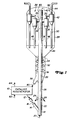
- Regenerated catalyst from a conduit 12 of a regeneration zone 10 is transferred by a conduit 14, at a rate regulated by a control valve 16, to a Y-section 18.
- Lift gas injected into the bottom of Y-section 18, by a conduit 20, carries the catalyst upward through a lower riser section 22.
- Feed is injected into the riser above lower riser section 22 by feed injection nozzles 24.
- the drawing shows this invention being used with a riser arrangement having a lift gas zone 22. It is not necessary that a lift gas zone be provided in the riser in order to enjoy the benefits of this invention.
- the mixture of feed, catalyst and lift gas travels up an intermediate section of the riser 26 that extends into a reactor vessel 28 and together with riser sections 26 and 22 form a first portion of the riser.
- the first portion of the riser empties a mixture of catalyst and gaseous components into a second portion 29 of the riser.
- gaseous components includes lift gas, product gases and vapors, and unconverted feed components.
- An interface 32 is located between the first portion and the second portion of the riser.
- a pair of outlets 34 connect the riser with the first stage 36 of two sets of cyclone separators 38.
- the second riser portion 29 has an open end 40 into which it receives a stripping vapor stream. Withdrawal of catalyst and gaseous components from outlets 34 dissipates the energy of the catalyst and gas mixture traveling upward into the riser so that an interface 32 is formed between a lower density catalyst region in the first portion of the riser and a higher catalyst density in the second portion of the riser at and above interface 32. Stripping gas entering from the open top of the riser also passes through the region of higher catalyst density in riser portion 29 and is withdrawn by the outlets 34.
- Riser portion 29 defines a disengagement chamber that operates as a disengaging zone 30.
- Gaseous components are separated from catalyst particles by cyclone separators 38. Gaseous products and catalyst pass from conduit 34 through the first stage cyclones 36 and then to the second stage cyclones 42. Gaseous reactor products are recovered overhead from the second stage cyclones by lines 44 and separated catalyst particles are returned to a dense bed 46 by dip-legs 48 from the first stage cyclones and second stage dip legs 50 from the second stage cyclones. Spent catalyst and entrained and adsorbed hydrocarbons flow downwardly from bed 46 into a stripper 52. As catalyst flows downwardly through stripper 52, it is cascaded back and forth by a series of baffles 54.
- the riser of this invention as arranged provides a unique region of catalyst and gas separation.
- catalyst travels up the first portion of the riser and through riser section 26 in a typical plug flow manner and at a velocity of between 6.1 to 30.5 m/sec (20 to 100 ft/sec) with a catalyst density of between 16 to 80 kg/m 3 (1 to 5 Ib/ft 3 ).
- the relatively uniform upward flow of the catalyst continues until it reaches the elevation of riser outlets 34.
- the energy of the gas and catalyst stream that travels up the riser immediately begins to dissipate when it reaches the elevation of riser outlets 34 due to the loss of pressure from the withdrawal of the gas and catalyst.
- the second portion of the riser is that portion where the velocity of the catalyst mixture passing up the riser begins to decrease due to the withdrawal of catalyst and gas from the riser or an increase in the flowing area of the riser.
- the disengaging zone is generally that portion of the riser that contains catalyst and is located above interface 32.
- This increased residence time of catalyst passing into the disengaging zone increases the catalyst density in the disengaging zone relative to the catalyst density in the first portion of the riser.
- the momentum of the upwardly flowing catalyst and gas particles keeps the higher density region of catalyst suspended above the riser outlets 34.
- the upward momentum of catalyst particles as they travel past the riser outlet 34 impacts a force on the higher density catalyst in the disengaging zone that also supports the higher density region of catalyst above the riser outlet 34.
- any gaseous components from the riser and from the stream of stripping fluid that enters through the top 40 of the riser also pass continually downward into outlets 34.
- the disengaging zone of the riser refers to that part of the riser where there is a substantial decrease in the velocity of the catalyst and gaseous mixture flowing up the riser and/or where the riser outlets withdraw catalyst and gaseous components for separation in the separation device.
- Catalyst in the first portion of the riser will have a velocity in a range of from 6.1 to 30.5 m/sec (20 to 100 ft/sec) and will have a density in a range of from 16 to 80 kg/m 3 (1 to 5 Ib/ft 3 ).
- the catalyst density increases to at least 1.1 to 20 and preferably 5 to 20 times the catalyst density in the first portion of the riser.
- the downward flow of stripping gas via open end 40 and the continual shooting of particles through the interface into the upper section of disengaging zone 30 keeps catalyst and gases circulating downwardly out of disengaging zone 30.
- the interface 32 and the higher density of catalyst particles in disengaging zone 30 aids in the stripping of hydrocarbon vapors from the catalyst before it enters the outlets 34.
- the relatively higher catalyst density of disengaging zone 30 provides a contacting zone that allows the stripping vapors to perform additional stripping of the catalyst particles prior to its entering into the cyclones.
- Catalyst withdrawn from the riser outlets may enter any type of a separation device that will complete the separation of the product gases from the catalyst.
- the outlets will feed the catalyst and gaseous mixture to a one or more stages of cyclone separators.
- Whatever separation device is used it should be of a type that is directly connected to the riser outlets and substantially closed in order to prevent the reentry of gaseous components into the dilute phase of the reactor vessel.
- cyclone separators can be either a single stage cyclone or a two- stage cyclone as depicted in Figure 1.
- the separators will operate in an ordinary manner separating gaseous components from the catalyst and removing gaseous products from the reactor vessel while returning separated catalyst to a stripping zone.
- Suitable stripping zones for this invention will be any type that can remove adsorbed hydrocarbons from the catalyst.
- the stripping zone will consist of the usual baffle arrangement as shown in Figure 1 wherein the catalyst particles are contacted countercurrently to an upward flow of stripping steam.
- the amount of stripping steam used in this process will be in the usual range, used for FCC operations and will normally vary between 1 to 3 kg of steam per 1000 kg of catalyst.
- the disengaging zone at the upper end of the riser has an arrangement that will substantially prevent catalyst from flowing out of the riser.
- catalyst is contained in the disengaging zone of the riser by providing an extended length 66 of riser above the outlets 34.
- an extended end 66 having the same diameter as the intermediate portion of the riser can be provided with enough length to prevent the ejection of catalyst particles out of the top of the riser.
- a simple extended end may require more length for extension 66 than is available in the reactor vessel 28.
- Figures 2-4 show a number of alternate arrangements for the end of the riser which will reduce the required height of the extension at the end of the riser to prevent any substantial ejection of catalyst from the top of the riser. These arrangements can also provide a method for increasing the catalyst density in the disengaging section of the riser.
- FIG 2 shows an alternate arrangement for the upper end of the riser shown in Figure 1.
- outlets 34 are located above the intermediate portion of riser 26.
- the riser has an enlarged diameter section 68.
- the enlarged portion of the riser serves to more quickly dissipate any velocity jet that may extend past outlets 34.
- the enlarged diameter will tend to catch any catalyst particles that migrate above the open top 70.
- the end of the riser can be provided with an optional baffle 72.
- Baffle 72 occludes the open end of the riser and directly prevents any catalyst particles from shooting past the open end of the riser.
- Baffle 72 can also be arranged to provide an annular opening 74.
- Opening 74 is necessary to allow stripping vapors to enter the upper end of the disengaging section.
- Annular opening 74 can be designed as a restriction to maintain a positive pressure drop for the stripping vapor stream as it enters the top of the riser. Again, the decay of the kinetic energy associated with the catalyst and gaseous stream moving up the riser will cause a collapsing of the catalyst flow regime that enters the upper portion of the disengaging zone so that an interface 76 forms between a lower density stream of catalyst and gases in section 26 of the riser and the relatively higher density catalyst section above interface 76.
- the upper section of the riser is enlarged over a longer portion of the riser that includes the riser outlets.
- Figure 3 shows such an arrangement wherein intermediate section 26 of the riser is followed by an enlarged portion 78.
- Riser outlets 34' are formed in the sidewall of enlarged section 78.
- the velocity of the mixture decreases thereby partially dissipating the energy of the stream before it passes outlets 34'.
- Initial dissipation of the stream energy below the outlets 34 reduces the momentum of the catalyst particles in the disengaging zone so that catalyst is more readily contained below the open top 80 of the riser.
- the decay of kinetic energy and the collapsing of the catalyst bed as it continues to fall back into the enlarged section of the disengaging zone will again establish an interface 82 between an upper region of higher catalyst density and a lower region of lower catalyst density.
- Figure 4 demonstrates another arrangement from modifying the end of the riser to prevent the outflow of catalyst from the end of the riser.
- intermediate section 26 is followed by the outlets 34 as also depicted in Figure 1.
- the riser has an end 84 that is closed by a head 88 except for one or more orifice openings 90.
- the head 88 deflects most catalyst that might shoot past the end of the riser and into the reactor vessel.
- Orifice openings 90 provide a restrictive flow passage for the entry of the stripping vapor stream and the reentry of any catalyst that migrates out through the orifice openings.
- This arrangement is particularly suitable for high velocity riser applications where catalyst particles still have a relatively high velocity when they impact on head 88 that can deflect catalyst out of the openings 90.
- An enlarged extension 92 of the riser catches any deflected catalyst that comes through the openings 90. Catalyst in extension 92 falls back through holes 90 and is returned to the disengaging zone 30' which operates with the interface 32'
- Figure 5 shows that another arrangement for preventing catalyst migration out of the top of the riser.
- the intermediate portion of the riser and the outlets have the same arrangement as that shown in Figures 1 and 4.
- An upper end 94 of the riser is closed by a head 96.
- a small diameter nozzle 98 extends upwardly from the top of head 96 and/or outwardly from the sides of the riser.
- Nozzle 98 provides a restrictive opening for the return of the stripping vapor stream into the disengaging zone 30". As stripping vapor flows into the disengaging zone 30" through nozzle 98, it creates a positive pressure drop along the extended length of the nozzle that prevents any outflow or deflection of catalyst particles out through the end of nozzle 98.
Landscapes
- Chemical & Material Sciences (AREA)
- Organic Chemistry (AREA)
- Chemical Kinetics & Catalysis (AREA)
- Oil, Petroleum & Natural Gas (AREA)
- Engineering & Computer Science (AREA)
- General Chemical & Material Sciences (AREA)
- Production Of Liquid Hydrocarbon Mixture For Refining Petroleum (AREA)
- Devices And Processes Conducted In The Presence Of Fluids And Solid Particles (AREA)
- Cyclones (AREA)
Priority Applications (13)
| Application Number | Priority Date | Filing Date | Title |
|---|---|---|---|
| US07/790,924 US5290430A (en) | 1991-11-13 | 1991-11-13 | Riser disengager with suspended catalyst separation zone |
| EP94301210A EP0668341B1 (de) | 1991-11-13 | 1994-02-21 | FCC-Verfahren mit Steigrohrreaktor-Auslösungszone mit Abtrennungszone für suspendierte Katalysatoren |
| AT94301210T ATE179205T1 (de) | 1991-11-13 | 1994-02-21 | Fcc-verfahren mit steigrohrreaktor-auslösungszone mit abtrennungszone für suspendierte katalysatoren |
| ES94301210T ES2130352T3 (es) | 1991-11-13 | 1994-02-21 | Procedimiento fcc que usa una zona de desprendimiento del tubo elevador del reactor con zona de separacion del catalizador suspendido. |
| AU55283/94A AU5528394A (en) | 1991-11-13 | 1994-02-21 | FCC process using reactor riser disengager with suspended catalyst separation zone |
| DE69418024T DE69418024T2 (de) | 1991-11-13 | 1994-02-21 | FCC-Verfahren mit Steigrohrreaktor-Auslösungszone mit Abtrennungszone für suspendierte Katalysatoren |
| CA002116163A CA2116163A1 (en) | 1991-11-13 | 1994-02-22 | Fcc process using reactor riser disengager with suspended catalyst separation zone |
| ZA941208A ZA941208B (en) | 1991-11-13 | 1994-02-22 | FCC process using reactor riser disengager with suspended catalyst separation zone |
| US08/201,495 US5417931A (en) | 1991-11-13 | 1994-02-24 | Riser disengager with suspended catalyst separation zone |
| CN94102538A CN1062890C (zh) | 1991-11-13 | 1994-02-28 | 一种新的流化催化裂化的方法及装置 |
| RU9494006801A RU2079541C1 (ru) | 1991-11-13 | 1994-02-28 | Способ проведения каталитического крекинга сырья в псевдоожиженном слое и устройство для его осуществления |
| US08/445,815 US5614083A (en) | 1991-11-13 | 1995-05-22 | Riser disengager with suspended catalyst separation zone |
| GR990401224T GR3030140T3 (en) | 1991-11-13 | 1999-05-06 | FCC process using reactor riser disengager with suspended catalyst separation zone. |
Applications Claiming Priority (7)
| Application Number | Priority Date | Filing Date | Title |
|---|---|---|---|
| US07/790,924 US5290430A (en) | 1991-11-13 | 1991-11-13 | Riser disengager with suspended catalyst separation zone |
| AU55283/94A AU5528394A (en) | 1991-11-13 | 1994-02-21 | FCC process using reactor riser disengager with suspended catalyst separation zone |
| EP94301210A EP0668341B1 (de) | 1991-11-13 | 1994-02-21 | FCC-Verfahren mit Steigrohrreaktor-Auslösungszone mit Abtrennungszone für suspendierte Katalysatoren |
| CA002116163A CA2116163A1 (en) | 1991-11-13 | 1994-02-22 | Fcc process using reactor riser disengager with suspended catalyst separation zone |
| ZA941208A ZA941208B (en) | 1991-11-13 | 1994-02-22 | FCC process using reactor riser disengager with suspended catalyst separation zone |
| RU9494006801A RU2079541C1 (ru) | 1991-11-13 | 1994-02-28 | Способ проведения каталитического крекинга сырья в псевдоожиженном слое и устройство для его осуществления |
| CN94102538A CN1062890C (zh) | 1991-11-13 | 1994-02-28 | 一种新的流化催化裂化的方法及装置 |
Publications (2)
| Publication Number | Publication Date |
|---|---|
| EP0668341A1 true EP0668341A1 (de) | 1995-08-23 |
| EP0668341B1 EP0668341B1 (de) | 1999-04-21 |
Family
ID=36950120
Family Applications (1)
| Application Number | Title | Priority Date | Filing Date |
|---|---|---|---|
| EP94301210A Expired - Lifetime EP0668341B1 (de) | 1991-11-13 | 1994-02-21 | FCC-Verfahren mit Steigrohrreaktor-Auslösungszone mit Abtrennungszone für suspendierte Katalysatoren |
Country Status (11)
| Country | Link |
|---|---|
| US (2) | US5290430A (de) |
| EP (1) | EP0668341B1 (de) |
| CN (1) | CN1062890C (de) |
| AT (1) | ATE179205T1 (de) |
| AU (1) | AU5528394A (de) |
| CA (1) | CA2116163A1 (de) |
| DE (1) | DE69418024T2 (de) |
| ES (1) | ES2130352T3 (de) |
| GR (1) | GR3030140T3 (de) |
| RU (1) | RU2079541C1 (de) |
| ZA (1) | ZA941208B (de) |
Families Citing this family (25)
| Publication number | Priority date | Publication date | Assignee | Title |
|---|---|---|---|---|
| US5614083A (en) * | 1991-11-13 | 1997-03-25 | Uop | Riser disengager with suspended catalyst separation zone |
| US5593643A (en) * | 1994-12-28 | 1997-01-14 | Uop | FCC arrangement with externally suspended catalyst separation zone |
| CN1095392C (zh) * | 1998-12-25 | 2002-12-04 | 中国石油化工集团公司 | 一种用于流化催化转化的提升管反应器 |
| RU2228349C2 (ru) * | 2000-05-18 | 2004-05-10 | Юоп Ллк | Способ и устройство для контактирования исходной реакционной смеси с немедленным отделением катализатора |
| CN1114479C (zh) * | 2000-06-02 | 2003-07-16 | 清华大学 | 分隔式分布板双射流管射流流化床 |
| US7008527B2 (en) * | 2002-10-23 | 2006-03-07 | Institut Francais Du Petrole | Process for catalytic cracking two integrated cracking zones of different degrees of severity followed by a cooling zone |
| US6902593B2 (en) * | 2003-02-26 | 2005-06-07 | Kellogg Brown And Root, Inc. | Separation device to remove fine particles |
| CN100473463C (zh) * | 2003-06-04 | 2009-04-01 | 国际壳牌研究有限公司 | 分离装置 |
| NO20040615L (no) * | 2004-02-11 | 2005-08-12 | Ellycrack As | Lav temperatur katalytisk krakking og omdannelsesprosess for oppgradering av tung raolje |
| RU2262527C1 (ru) * | 2004-05-18 | 2005-10-20 | Открытое акционерное общество "Славнефть-Ярославнефтеоргсинтез" | Способ каталитического крекинга тяжелых нефтяных фракций |
| US7682501B2 (en) * | 2004-12-23 | 2010-03-23 | Abb Lummus Global, Inc. | Processing of different feeds in a fluid catalytic cracking unit |
| US7390339B1 (en) | 2005-05-05 | 2008-06-24 | Hach Ultra Analytics, Inc. | Vortex separator in particle detection systems |
| CN101045881B (zh) * | 2006-03-31 | 2010-06-23 | 中国石油化工股份有限公司 | 一种催化转化装置 |
| JP2010500435A (ja) * | 2006-08-08 | 2010-01-07 | シエル・インターナシヨネイル・リサーチ・マーチヤツピイ・ベー・ウイ | 接触分解ライザー反応器 |
| US7758817B2 (en) * | 2006-08-09 | 2010-07-20 | Uop Llc | Device for contacting high contaminated feedstocks with catalyst in an FCC unit |
| US20080081006A1 (en) * | 2006-09-29 | 2008-04-03 | Myers Daniel N | Advanced elevated feed distribution system for very large diameter RCC reactor risers |
| CN101191070B (zh) * | 2006-11-30 | 2011-02-09 | 中国石油化工股份有限公司石油化工科学研究院 | 一种生产低碳烯烃的方法 |
| US20090277514A1 (en) * | 2008-05-09 | 2009-11-12 | D-Cok, Llc | System and method to control catalyst migration |
| FR2966161B1 (fr) * | 2010-10-15 | 2013-12-20 | Total Raffinage Marketing | Procede de reaction et de stripage etage dans une unite de fcc pour maximisation de la production d'olefines |
| EP3062922B1 (de) * | 2013-10-29 | 2018-12-19 | Dow Global Technologies LLC | Zyklonabscheideranordnung mit plenum mit niedriger verweilzeit in einem wirbelschichtreaktorbehälter |
| US20160168050A1 (en) * | 2014-12-12 | 2016-06-16 | Uop Llc | Process and apparatus with catalyst heating in a riser |
| US20160168051A1 (en) * | 2014-12-12 | 2016-06-16 | Uop Llc | Process and apparatus for heating catalyst in a regenerator |
| US9707533B2 (en) * | 2015-12-01 | 2017-07-18 | Dow Global Technologies Llc | Fluidized catalyst stripping unit for displacing entrained gas from catalyst particles |
| FR3073153B1 (fr) * | 2017-11-08 | 2019-11-22 | IFP Energies Nouvelles | Nouveau separateur gaz solide pour les unites de craquage catalytique possedant un riser externe |
| CN108893142B (zh) * | 2018-08-17 | 2020-09-01 | 中石化(洛阳)科技有限公司 | 一种重油裂化装置及重油裂化方法 |
Citations (5)
| Publication number | Priority date | Publication date | Assignee | Title |
|---|---|---|---|---|
| US4377470A (en) * | 1981-04-20 | 1983-03-22 | Ashland Oil, Inc. | Immobilization of vanadia deposited on catalytic materials during carbo-metallic oil conversion |
| US4394349A (en) * | 1981-07-06 | 1983-07-19 | Standard Oil Company (Indiana) | Apparatus for the fluidized catalytic cracking of hydrocarbon feedstock |
| US4406776A (en) * | 1982-08-25 | 1983-09-27 | Uop Inc. | Fluidized catalytic cracking process and apparatus |
| US4678642A (en) * | 1985-01-10 | 1987-07-07 | Ashland Oil, Inc. | Ballistic separation of particles in a progressive flow reactor |
| US5266187A (en) * | 1992-05-19 | 1993-11-30 | Amoco Corporation | Method for catalytic cracking with post-cyclone inertial separator |
Family Cites Families (14)
| Publication number | Priority date | Publication date | Assignee | Title |
|---|---|---|---|---|
| US3817872A (en) * | 1972-02-07 | 1974-06-18 | Standard Oil Co | Cyclone separation method and apparatus |
| AR207247A1 (es) * | 1975-01-16 | 1976-09-22 | Pullman Inc | Colector de camara de sobrepresion externa para regenerador de aparato de termodesintegracion catalitica de fluido |
| AT364745B (de) * | 1975-03-24 | 1981-11-10 | Ashland Oil Inc | Verfahren und vorrichtung zum abscheiden feiner feststoffteilchen aus stroemenden gasen |
| US4295961A (en) * | 1979-11-23 | 1981-10-20 | Standard Oil Company (Indiana) | Method and apparatus for improved fluid catalytic riser reactor cracking of hydrocarbon feedstocks |
| US4721603A (en) * | 1983-06-13 | 1988-01-26 | Chevron Research Company | Separation of reacted hydrocarbons and catalyst in fluidized catalytic cracking |
| US4786622A (en) * | 1984-01-09 | 1988-11-22 | Ashland Oil, Inc. | Regeneration of fluid solid particles and separation of solid particles from combustion product flue gases |
| US5055177A (en) * | 1984-05-21 | 1991-10-08 | Mobil Oil Corporation | Closed cyclone FCC catalyst separation method and apparatus |
| US4737346A (en) * | 1984-05-21 | 1988-04-12 | Mobil Oil Corporation | Closed cyclone FCC catalyst separation with stripping gas injection and direct steam injection |
| US4869880A (en) * | 1984-06-08 | 1989-09-26 | Ashland Oil, Inc. | Apparatus for the separation of solid particulates from a gaseous effluent |
| US4792437A (en) * | 1984-06-08 | 1988-12-20 | Ashland Oil, Inc. | Apparatus for the separation of solid particulates from a gaseous effluent |
| US4701307A (en) * | 1984-09-19 | 1987-10-20 | Ashland Oil, Inc. | Vented riser |
| US4572780A (en) * | 1984-10-22 | 1986-02-25 | Mobil Oil Corporation | Multistage stripper for FCC unit with catalyst separation by spinning |
| US4714541A (en) * | 1985-11-22 | 1987-12-22 | Mobil Oil Corporation | Method and apparatus for improving cyclone efficiency |
| US5141625A (en) * | 1989-12-27 | 1992-08-25 | Uop | Second stage stripping and lift gas supply |
-
1991
- 1991-11-13 US US07/790,924 patent/US5290430A/en not_active Expired - Fee Related
-
1994
- 1994-02-21 EP EP94301210A patent/EP0668341B1/de not_active Expired - Lifetime
- 1994-02-21 ES ES94301210T patent/ES2130352T3/es not_active Expired - Lifetime
- 1994-02-21 AT AT94301210T patent/ATE179205T1/de not_active IP Right Cessation
- 1994-02-21 AU AU55283/94A patent/AU5528394A/en not_active Abandoned
- 1994-02-21 DE DE69418024T patent/DE69418024T2/de not_active Expired - Fee Related
- 1994-02-22 CA CA002116163A patent/CA2116163A1/en not_active Abandoned
- 1994-02-22 ZA ZA941208A patent/ZA941208B/xx unknown
- 1994-02-24 US US08/201,495 patent/US5417931A/en not_active Expired - Fee Related
- 1994-02-28 RU RU9494006801A patent/RU2079541C1/ru active
- 1994-02-28 CN CN94102538A patent/CN1062890C/zh not_active Expired - Fee Related
-
1999
- 1999-05-06 GR GR990401224T patent/GR3030140T3/el unknown
Patent Citations (5)
| Publication number | Priority date | Publication date | Assignee | Title |
|---|---|---|---|---|
| US4377470A (en) * | 1981-04-20 | 1983-03-22 | Ashland Oil, Inc. | Immobilization of vanadia deposited on catalytic materials during carbo-metallic oil conversion |
| US4394349A (en) * | 1981-07-06 | 1983-07-19 | Standard Oil Company (Indiana) | Apparatus for the fluidized catalytic cracking of hydrocarbon feedstock |
| US4406776A (en) * | 1982-08-25 | 1983-09-27 | Uop Inc. | Fluidized catalytic cracking process and apparatus |
| US4678642A (en) * | 1985-01-10 | 1987-07-07 | Ashland Oil, Inc. | Ballistic separation of particles in a progressive flow reactor |
| US5266187A (en) * | 1992-05-19 | 1993-11-30 | Amoco Corporation | Method for catalytic cracking with post-cyclone inertial separator |
Also Published As
| Publication number | Publication date |
|---|---|
| ATE179205T1 (de) | 1999-05-15 |
| ES2130352T3 (es) | 1999-07-01 |
| DE69418024T2 (de) | 1999-08-12 |
| CN1107502A (zh) | 1995-08-30 |
| DE69418024D1 (de) | 1999-05-27 |
| US5417931A (en) | 1995-05-23 |
| EP0668341B1 (de) | 1999-04-21 |
| US5290430A (en) | 1994-03-01 |
| ZA941208B (en) | 1994-11-30 |
| AU5528394A (en) | 1995-09-21 |
| CA2116163A1 (en) | 1995-08-23 |
| RU2079541C1 (ru) | 1997-05-20 |
| GR3030140T3 (en) | 1999-08-31 |
| CN1062890C (zh) | 2001-03-07 |
Similar Documents
| Publication | Publication Date | Title |
|---|---|---|
| EP0668341B1 (de) | FCC-Verfahren mit Steigrohrreaktor-Auslösungszone mit Abtrennungszone für suspendierte Katalysatoren | |
| US5104517A (en) | Vented riser apparatus and method | |
| US6248297B1 (en) | FCC reactor arrangement for sequential disengagement and progressive temperature reduction | |
| US5176815A (en) | FCC process with secondary conversion zone | |
| US6113776A (en) | FCC process with high temperature cracking zone | |
| US4988430A (en) | Supplying FCC lift gas directly from product vapors | |
| ZA200204751B (en) | Method and device for catalytic cracking comprising in parallel at least an upflow reactor and at least a downflow reactor. | |
| US6491875B1 (en) | Fluidized particle contacting process with elongated combustor | |
| US5393415A (en) | FCC process with enclosed vented riser | |
| US5141625A (en) | Second stage stripping and lift gas supply | |
| US5158669A (en) | Disengager stripper | |
| US5449498A (en) | FCC stripper with multiple integrated disengager | |
| US5308474A (en) | Plug flow vented riser | |
| US5316662A (en) | Integrated disengager stripper and its use in fluidized catalytic cracking process | |
| US5314611A (en) | External integrated disengager stripper and its use in fluidized catalytic cracking process | |
| US8535610B2 (en) | Apparatus for regenerating catalyst | |
| US6139720A (en) | FCC process with carbon monoxide management and hot stripping | |
| US5614083A (en) | Riser disengager with suspended catalyst separation zone | |
| US5328592A (en) | FCC reactor with tube sheet separation | |
| US5182085A (en) | Vented riser apparatus and method | |
| US5593643A (en) | FCC arrangement with externally suspended catalyst separation zone | |
| US5393414A (en) | FCC process with enclosed vented riser | |
| EP0593827B1 (de) | Dissipationsplatten enthaltenden Abflussabstreibeinrichtung für FCC-Verfahren | |
| US8815762B2 (en) | Process for regenerating catalyst | |
| KR970010861B1 (ko) | 부유 촉매 분리 대역이 있는 반응기 상승관 유리 대역을 이용한 fcc법 |
Legal Events
| Date | Code | Title | Description |
|---|---|---|---|
| PUAI | Public reference made under article 153(3) epc to a published international application that has entered the european phase |
Free format text: ORIGINAL CODE: 0009012 |
|
| AK | Designated contracting states |
Kind code of ref document: A1 Designated state(s): AT BE DE ES FR GB GR IT NL PT SE |
|
| 17P | Request for examination filed |
Effective date: 19960124 |
|
| 17Q | First examination report despatched |
Effective date: 19980311 |
|
| GRAG | Despatch of communication of intention to grant |
Free format text: ORIGINAL CODE: EPIDOS AGRA |
|
| GRAG | Despatch of communication of intention to grant |
Free format text: ORIGINAL CODE: EPIDOS AGRA |
|
| GRAG | Despatch of communication of intention to grant |
Free format text: ORIGINAL CODE: EPIDOS AGRA |
|
| GRAH | Despatch of communication of intention to grant a patent |
Free format text: ORIGINAL CODE: EPIDOS IGRA |
|
| GRAH | Despatch of communication of intention to grant a patent |
Free format text: ORIGINAL CODE: EPIDOS IGRA |
|
| GRAH | Despatch of communication of intention to grant a patent |
Free format text: ORIGINAL CODE: EPIDOS IGRA |
|
| GRAA | (expected) grant |
Free format text: ORIGINAL CODE: 0009210 |
|
| AK | Designated contracting states |
Kind code of ref document: B1 Designated state(s): AT BE DE ES FR GB GR IT NL PT SE |
|
| PG25 | Lapsed in a contracting state [announced via postgrant information from national office to epo] |
Ref country code: SE Free format text: THE PATENT HAS BEEN ANNULLED BY A DECISION OF A NATIONAL AUTHORITY Effective date: 19990421 Ref country code: AT Free format text: LAPSE BECAUSE OF FAILURE TO SUBMIT A TRANSLATION OF THE DESCRIPTION OR TO PAY THE FEE WITHIN THE PRESCRIBED TIME-LIMIT Effective date: 19990421 |
|
| REF | Corresponds to: |
Ref document number: 179205 Country of ref document: AT Date of ref document: 19990515 Kind code of ref document: T |
|
| ITF | It: translation for a ep patent filed | ||
| ET | Fr: translation filed | ||
| REF | Corresponds to: |
Ref document number: 69418024 Country of ref document: DE Date of ref document: 19990527 |
|
| REG | Reference to a national code |
Ref country code: ES Ref legal event code: FG2A Ref document number: 2130352 Country of ref document: ES Kind code of ref document: T3 |
|
| REG | Reference to a national code |
Ref country code: PT Ref legal event code: SC4A Free format text: AVAILABILITY OF NATIONAL TRANSLATION Effective date: 19990715 |
|
| PLBE | No opposition filed within time limit |
Free format text: ORIGINAL CODE: 0009261 |
|
| STAA | Information on the status of an ep patent application or granted ep patent |
Free format text: STATUS: NO OPPOSITION FILED WITHIN TIME LIMIT |
|
| 26N | No opposition filed | ||
| PGFP | Annual fee paid to national office [announced via postgrant information from national office to epo] |
Ref country code: NL Payment date: 20010213 Year of fee payment: 8 |
|
| REG | Reference to a national code |
Ref country code: GB Ref legal event code: IF02 |
|
| PGFP | Annual fee paid to national office [announced via postgrant information from national office to epo] |
Ref country code: FR Payment date: 20020130 Year of fee payment: 9 |
|
| PGFP | Annual fee paid to national office [announced via postgrant information from national office to epo] |
Ref country code: DE Payment date: 20020131 Year of fee payment: 9 |
|
| PGFP | Annual fee paid to national office [announced via postgrant information from national office to epo] |
Ref country code: GB Payment date: 20020201 Year of fee payment: 9 |
|
| PGFP | Annual fee paid to national office [announced via postgrant information from national office to epo] |
Ref country code: PT Payment date: 20020208 Year of fee payment: 9 |
|
| PGFP | Annual fee paid to national office [announced via postgrant information from national office to epo] |
Ref country code: BE Payment date: 20020307 Year of fee payment: 9 |
|
| PGFP | Annual fee paid to national office [announced via postgrant information from national office to epo] |
Ref country code: ES Payment date: 20020311 Year of fee payment: 9 |
|
| PG25 | Lapsed in a contracting state [announced via postgrant information from national office to epo] |
Ref country code: NL Free format text: LAPSE BECAUSE OF NON-PAYMENT OF DUE FEES Effective date: 20020901 |
|
| NLV4 | Nl: lapsed or anulled due to non-payment of the annual fee |
Effective date: 20020901 |
|
| PG25 | Lapsed in a contracting state [announced via postgrant information from national office to epo] |
Ref country code: GB Free format text: LAPSE BECAUSE OF NON-PAYMENT OF DUE FEES Effective date: 20030221 |
|
| PG25 | Lapsed in a contracting state [announced via postgrant information from national office to epo] |
Ref country code: ES Free format text: LAPSE BECAUSE OF NON-PAYMENT OF DUE FEES Effective date: 20030222 |
|
| PG25 | Lapsed in a contracting state [announced via postgrant information from national office to epo] |
Ref country code: BE Free format text: LAPSE BECAUSE OF NON-PAYMENT OF DUE FEES Effective date: 20030228 |
|
| PG25 | Lapsed in a contracting state [announced via postgrant information from national office to epo] |
Ref country code: PT Free format text: LAPSE BECAUSE OF NON-PAYMENT OF DUE FEES Effective date: 20030831 |
|
| PG25 | Lapsed in a contracting state [announced via postgrant information from national office to epo] |
Ref country code: DE Free format text: LAPSE BECAUSE OF NON-PAYMENT OF DUE FEES Effective date: 20030902 |
|
| GBPC | Gb: european patent ceased through non-payment of renewal fee | ||
| PG25 | Lapsed in a contracting state [announced via postgrant information from national office to epo] |
Ref country code: FR Free format text: LAPSE BECAUSE OF NON-PAYMENT OF DUE FEES Effective date: 20031031 |
|
| REG | Reference to a national code |
Ref country code: FR Ref legal event code: ST |
|
| REG | Reference to a national code |
Ref country code: ES Ref legal event code: FD2A Effective date: 20030222 |
|
| PG25 | Lapsed in a contracting state [announced via postgrant information from national office to epo] |
Ref country code: IT Free format text: LAPSE BECAUSE OF NON-PAYMENT OF DUE FEES;WARNING: LAPSES OF ITALIAN PATENTS WITH EFFECTIVE DATE BEFORE 2007 MAY HAVE OCCURRED AT ANY TIME BEFORE 2007. THE CORRECT EFFECTIVE DATE MAY BE DIFFERENT FROM THE ONE RECORDED. Effective date: 20050221 |
|
| PGFP | Annual fee paid to national office [announced via postgrant information from national office to epo] |
Ref country code: GR Payment date: 20081231 Year of fee payment: 16 |