EP0668442A1 - Axialkolben-Taumelscheiben-Kompressor - Google Patents
Axialkolben-Taumelscheiben-Kompressor Download PDFInfo
- Publication number
- EP0668442A1 EP0668442A1 EP95101202A EP95101202A EP0668442A1 EP 0668442 A1 EP0668442 A1 EP 0668442A1 EP 95101202 A EP95101202 A EP 95101202A EP 95101202 A EP95101202 A EP 95101202A EP 0668442 A1 EP0668442 A1 EP 0668442A1
- Authority
- EP
- European Patent Office
- Prior art keywords
- counterweight
- swash plate
- ring
- drive shaft
- plate compressor
- Prior art date
- Legal status (The legal status is an assumption and is not a legal conclusion. Google has not performed a legal analysis and makes no representation as to the accuracy of the status listed.)
- Granted
Links
Images


Classifications
-
- F—MECHANICAL ENGINEERING; LIGHTING; HEATING; WEAPONS; BLASTING
- F16—ENGINEERING ELEMENTS AND UNITS; GENERAL MEASURES FOR PRODUCING AND MAINTAINING EFFECTIVE FUNCTIONING OF MACHINES OR INSTALLATIONS; THERMAL INSULATION IN GENERAL
- F16F—SPRINGS; SHOCK-ABSORBERS; MEANS FOR DAMPING VIBRATION
- F16F15/00—Suppression of vibrations in systems; Means or arrangements for avoiding or reducing out-of-balance forces, e.g. due to motion
- F16F15/22—Compensation of inertia forces
-
- F—MECHANICAL ENGINEERING; LIGHTING; HEATING; WEAPONS; BLASTING
- F04—POSITIVE - DISPLACEMENT MACHINES FOR LIQUIDS; PUMPS FOR LIQUIDS OR ELASTIC FLUIDS
- F04B—POSITIVE-DISPLACEMENT MACHINES FOR LIQUIDS; PUMPS
- F04B27/00—Multi-cylinder pumps specially adapted for elastic fluids and characterised by number or arrangement of cylinders
- F04B27/08—Multi-cylinder pumps specially adapted for elastic fluids and characterised by number or arrangement of cylinders having cylinders coaxial with, or parallel or inclined to, main shaft axis
- F04B27/0873—Component parts, e.g. sealings; Manufacturing or assembly thereof
- F04B27/0895—Component parts, e.g. sealings; Manufacturing or assembly thereof driving means
-
- F—MECHANICAL ENGINEERING; LIGHTING; HEATING; WEAPONS; BLASTING
- F04—POSITIVE - DISPLACEMENT MACHINES FOR LIQUIDS; PUMPS FOR LIQUIDS OR ELASTIC FLUIDS
- F04B—POSITIVE-DISPLACEMENT MACHINES FOR LIQUIDS; PUMPS
- F04B27/00—Multi-cylinder pumps specially adapted for elastic fluids and characterised by number or arrangement of cylinders
- F04B27/08—Multi-cylinder pumps specially adapted for elastic fluids and characterised by number or arrangement of cylinders having cylinders coaxial with, or parallel or inclined to, main shaft axis
- F04B27/10—Multi-cylinder pumps specially adapted for elastic fluids and characterised by number or arrangement of cylinders having cylinders coaxial with, or parallel or inclined to, main shaft axis having stationary cylinders
- F04B27/1036—Component parts, details, e.g. sealings, lubrication
Definitions
- the invention relates to an axial piston swash plate compressor according to the preamble of claim 1.
- Such swash plate compressors which are known in principle in DE-A 42 29 978, are often used in the air conditioning system of passenger cars, being driven by the vehicle engine. Since a constant flow rate regardless of the speed is desired for the function of the air conditioning system, the swash plate is pivoted so that a small stroke is generally achieved at high speeds and a large stroke at low speeds. Swiveling the swashplate creates an imbalance, the size of which depends on the degree of swiveling. So far, the swash plate and the parts rotating with it have been balanced so that a mass balance in small strokes, i.e. towards high speeds, i.e. where it is primarily needed because of the quadratic speed dependency. Outside of this working area, an imbalance arises which results in vibrations at low speeds.
- the object of the invention is to provide a swash plate compressor of the generic type, in which an extensive mass balance is achieved over the entire speed range. This object is achieved by the features specified in the characterizing part of claim 1.
- a partial mass balance is achieved in the lower speed range by the first counterweight (possibly together with a counterweight, if present), while the second counterweight is held in its initial position by the spring. From a certain speed, for example from 1500 to 2000 rpm, the second counterweight is moved outwards by overcoming the force of the spring by the centrifugal force, so that the effect of the first counterweight is increasingly compensated and then a largely complete mass balance is achieved in the upper speed range becomes.
- a disk is connected to the drive shaft, which is provided on one side of the axis of rotation with the first counterweight and diametrically opposite this has a radial guide for the second counterweight, which is provided with an inner and an outer stop for the second counterweight, wherein the spring strives to hold the second counterweight against the inner stop.
- a disc is attached to the drive shaft, which is provided with the first counterweight on one side of the axis of rotation, the second counterweight being pivotably attached to the disc and with increasing speed due to the centrifugal force against the force of the spring is pivoted into a position in which it compensates for the effect of the first counterweight.
- the second counterweight can be formed by a ring surrounding the drive shaft, which is pivotally attached to the disc on one side.
- the disk can have an annular recess in which the ring is arranged with radial play, the radially inner wall of the recess forming a stop for the ring both in the lower and in the upper speed range.
- the spring acting on the ring can be a leg spring which is arranged laterally next to the ring and is attached at one end to the pivot pin of the ring and at the other end to the ring.
- the leg spring may extend about 540, with its other end connected to the ring at a location approximately diametrically opposite the pivot.
- the width of the ring is larger at its location diametrically opposite the first counterweight than at the location adjacent to the first counterweight.
- the first counterweight can also be provided in the annular recess of the disc.
- the swash plate compressor shown in FIG. 1 has a housing 1 to which a cylinder block 2 with a plurality of axial cylinder bores 3 is flanged.
- a drive shaft 4 is mounted in the housing 1 and in the cylinder block 2.
- a swash plate 5 is mounted on the drive shaft 4, which is in drive connection with a drive flange 6 arranged on the drive shaft 4 in a rotationally fixed manner stands and can be pivoted about a transverse axis 7 by a device, not shown, or automatically as a function of the speed and / or the delivery pressure.
- a ring 8 is mounted, which is fixed against rotation in the housing 1.
- a piston 9 is slidably arranged in each cylinder bore 3, the piston rod 10 of which is connected on the one hand to the piston 9 and on the other hand to the ring 8 by a ball joint 11.
- the swash plate 5 is carried along by the drive flange 6, the pistons 9 carrying out a more or less large stroke movement depending on the size of the inclined position of the swash plate.
- the compressor When using such a compressor in the air conditioning system of a passenger car, the compressor is driven by the vehicle engine and thus at a rapidly changing speed. Since it is desirable for the function of the air conditioning system that the delivery rate of the air conditioning compressor is largely constant, the inclined position of the swash plate is automatically adjusted by means not shown so that a large piston stroke is generally achieved at low speeds and a small piston stroke at high speeds becomes. With the change in the inclined position of the swash plate 5, the unbalance of the rotating parts, i.e. the swash plate 5 and the drive flange 6, also changes. In practice, these jointly rotating parts are mass-balanced for the most sensitive working area, i.e.
- an additional device 12 is arranged on the drive shaft 4 or on a pulley 13 connected to the drive shaft, which is connected to the shaft 4 in a rotationally fixed manner.
- the additional device 12 has a disk 14 with an annular recess 15 which is concentric with the axis of rotation of the shaft 4 and in which, as can be seen in particular from FIGS.
- a first counterweight 16 firmly connected to the disk 14 and a second counterweight 17 is arranged, which in this embodiment has the form of a ring which is arranged in the recess 15 with radial play and is pivotally mounted on a pivot 18 on one side of the axis of rotation.
- the ring 17 is under the influence of a leg spring 19, one end 19a of which is hooked onto the pivot pin 18 and the other end 19b of which is attached to a pin 20 which is approximately diametrically opposite the pivot pin 18 on the ring 17.
- This spring endeavors to pivot the ring 17 into the position shown in FIG. 2, in which the ring 17 rests on the inner wall 21 of the recess 15 on the side opposite the first counterweight 16.
- the first counterweight 16 is designed such that it effects a largely complete mass balance in the lower speed range. If the speed increases, from a certain speed, for example 1500 to 2000 rpm, the ring 17 is pivoted outward against the action of the spring 19 about the pivot 18 by the centrifugal force and thereby increasingly compensates for the effect of the first counterweight 16 At a certain speed, the ring 17 then lies against the inner wall 21 of the recess 15 at a location adjacent to the first counterweight 16, as shown in FIG. In this position of the ring 17, a largely complete mass balance of the rotating unit consisting of the swash plate 5 and drive flange 6 is achieved.
- the ring 17 must be designed accordingly, which is effected in the exemplary embodiment in that its width is larger in the area diametrically opposite the first counterweight 16 than in the area adjacent to the counterweight. In order to avoid tilting moments, the center of gravity of the ring 17 and the first counterweight 16 lie in one plane.
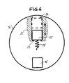
- a second embodiment of the additional device according to the invention is shown schematically, which in turn has a disk 14 'rotating with the drive shaft, which has a first counterweight 16' attached to the disk 14 'and diametrically opposite a radial guide 22 for a second Counterweight 17 ', which is held in the lower speed range by a spring 19' in contact with an inner stop 23 and is moved with increasing speed against the action of the spring 19 'by centrifugal force until it rests on the outer stop 24 , as shown in dashed lines.
- the effect of this additional device is basically the same as that of the first exemplary embodiment according to FIGS. 1 to 3.
- the first counterweight can be part of the parts 5 and 6 rotating around one another.
Landscapes
- Engineering & Computer Science (AREA)
- General Engineering & Computer Science (AREA)
- Mechanical Engineering (AREA)
- Manufacturing & Machinery (AREA)
- Physics & Mathematics (AREA)
- Acoustics & Sound (AREA)
- Aviation & Aerospace Engineering (AREA)
- Compressors, Vaccum Pumps And Other Relevant Systems (AREA)
Abstract
Description
- Die Erfindung betrifft ein Axialkolben-Taumelscheiben-Kompressor entsprechend dem Oberbegriff des Anspruchs 1.
- Derartige, im Prinzip in der DE-A 42 29 978 bekannten Taumelscheiben-Kompressorenwerden häufig in der Klimaanlage von Personenkraftwagen verwendet, wobei sie von dem Fahrzeugmotor angetrieben werden. Da für die Funktion der Klimaanlage eine konstante Fördermenge unabhängig von der Drehzahl erwünscht ist, wird die Taumelscheibe so verschwenkt, daß in der Regel bei hohen Drehzahlen ein kleiner Hub und bei niedrigen Drehzahlen ein großer Hub erreicht wird. Durch das Verschwenken der Taumelscheibe entsteht eine Unwucht, deren Größe von dem Grad der Verschwenkung abhängt. Bisher wurde die Taumelscheibe und die mit ihr umlaufenden Teile so ausgewuchtet, daß ein Massenausgleich bei kleinen Hüben, d.h. zu hohen Drehzahlen hin, also dann, wo er wegen der quadratischen Drehzahlabhängigkeit vor allem benötigt wird, erreicht wurde. Außerhalb dieses Arbeitsbereichs entsteht eine Unwucht, die bei niedrigen Drehzahlen Vibrationen zur Folge hat.
- Aufgabe der Erfindung ist es, einen Taumelscheiben-Kompressor der gattungsgemäßen Art zu schaffen, bei dem ein weitgehender Massenausgleich über den gesamten Drehzahlbereich erreicht wird. Diese Aufgabe wird erfindungsgemäß durch die im Kennzeichen des Anspruchs 1 angegebenen Merkmale gelöst.
- Bei dem erfindungsgemäßen Vorschlag wird im unteren Drehzahlbereich durch das erste Gegengewicht (gegebenenfalls zusammenmit einem etwa vorhanden Gegengewicht) ein teilweiser Massenausgleich erreicht, während das zweite Gegengewicht durch die Feder in seiner Ausgangslage gehalten wird. Ab einer bestimmten Drehzahl, beispielsweise ab 1500 bis 2000 U/min, wird das zweite Gegengewicht unter Überwindung der Kraft der Feder durch die Fliehkraft nach außen bewegt, so daß die Wirkung des ersten Gegengewichts zunehmend kompensiert und dann im oberen Drehzahlbereich ein weitgehend vollständiger Massenausgleich erzielt wird.
- Vorzugsweise ist mit der Antriebswelle eine Scheibe verbunden, die auf einer Seite der Drehachse mit dem ersten Gegengewicht versehen ist und diesem diametral gegenüberliegend eine radiale Führung für das zweite Gegengewicht aufweist, die mit einem inneren und einem äußeren Anschlag für das zweite Gegengewicht versehen ist, wobei die Feder bestrebt ist, das zweite Gegengewicht in Anlage an dem inneren Anschlag zu halten.
- Nach einem anderen Vorschlag der Erfindung ist auf der Antriebswelle eine Scheibe angebracht, die auf der einen Seite der Drehachse mit dem ersten Gegengewicht versehen ist, wobei das zweite Gegengewicht schwenkbar an der Scheibe angebracht ist und mit steigender Drehzahl durch die Fliehkraft entgegen der Kraft der Feder in eine Stellung geschwenkt wird, in der sie die Wirkung des ersten Gegengewichts kompensiert. Das zweite Gegengewicht kann von einem die Antriebswelle umgebenden Ring gebildet sein, der auf einer Seite schwenkbar an der Scheibe angebracht ist. Die Scheibe kann eine ringförmige Ausnehmung aufweisen, in welcher der Ring mit radialem Spiel angeordnet ist, wobei die radial innere Wand der Ausnehmung einen Anschlag für den Ring sowohl im unteren als auch im oberen Drehzahlbereich bildet. Die auf den Ring wirkende Feder kann eine Schenkelfeder sein, die seitlich neben dem Ring angeordnet ist und mit einem Ende am Drehzapfen des Ringes und mit dem anderen Ende am Ring angebracht ist. Die Schenkelfeder kann sich um etwa 540 erstrecken, wobei ihr anderes Ende an einer dem Drehzapfen etwa diametral gegenüberliegenden Stelle mit dem Ring verbunden ist. Die Breite des Ringes ist an seiner dem ersten Gegengewicht diametral gegenüberliegenden Stelle größer als an der dem ersten Gegengewicht benachbarten Stelle. Das erste Gegengewicht kann ebenfalls in der ringförmigen Ausnehmung der Scheibe vorgesehen sein.
- Zwei Ausführungsbeispiele der Erfindung werden im folgenden unter Bezugnahme auf die Zeichnungen beschrieben. Es zeigt:
- Fig. 1 einen Teil-Längsschnitt eines Axialkolben-Taumelscheibenkompressors mit einem ersten Ausführungsbeispiel der erfindungsgemäßen Zusatzvorrichtung zur Unwuchtkompensierung,
- Fig. 2 eine Ansicht der Vorrichtung zur Unwuchtkompensierung von Fig. 1, wobei das zweite Gegengewicht in der Stellung im unteren Drehzahlbereich dargestellt ist,
- Fig. 3 eine Ansicht ähnlich Fig. 2, wobei das zweite Gegengewicht in der Stellung im oberen Drehzahlbereich dargestellt ist, und
- Fig. 4 eine schematische Darstellung eines zweiten Ausführungsbeispiels einer Zusatzvorrichtung zur Unwuchtkompensierung.
- Der in Fig. 1 dargestellte Taumelscheibenkompressor weist ein Gehäuse 1 auf, an das ein Zylinderblock 2 mit einer Mehrzahl von axialen Zylinderbohrungen 3 angeflanscht ist. In dem Gehäuse 1 und in dem Zylinderblock 2 ist eine Antriebswelle 4 gelagert. Innerhalb des Gehäuses 1 ist auf der Antriebswelle 4 eine Taumelscheibe 5 gelagert, die mit einem drehfest auf der Antriebswelle 4 angeordneten Antriebsflansch 6 in Antriebsverbindung steht und durch eine nicht dargestellte Einrichtung oder auch selbsttätig in Abhängigkeit von der Drehzahl und/oder vom Förderdruck um eine Querachse 7 schwenkbar ist. Auf der Taumelscheibe 5 ist ein Ring 8 gelagert, der gegen Drehung im Gehäuse 1 festgelegt ist. In jeder Zylinderbohrung 3 ist ein Kolben 9 verschiebbar angeordnet, dessen Kolbenstange 10 einerseits mit dem Kolben 9 und andererseits mit dem Ring 8 jeweils durch ein Kugelgelenk 11 verbunden ist. Bei Drehung der Antriebswelle 4 wird die Taumelscheibe 5 von dem Antriebsflansch 6 mitgenommen, wobei die Kolben 9 je nach Größe der Schrägstellung der Taumelscheibe eine mehr oder weniger große Hubbewegung ausführen. Durch Veränderung der Schrägstellung der Taumelscheibe 5 kann somit der Hub der Kolben 9 und damit die Fördermenge des Kompressors verändert werden.
- Bei Verwendung eines derartigen Kompressors in der Klimaanlage eines Personenkraftwagens wird der Kompressor von dem Fahrzeugmotor und damit mit stark wechselnder Drehzahl angetrieben. Da es für die Funktion der Klimaanlage wünschenswert ist, daß die Fördermenge des Klimakompressors weitgehend konstant ist, wird die Schrägstellung der Taumelscheibe durch nicht gezeigte Mittel automatisch so eingestellt, daß in der Regel bei geringen Drehzahlen ein großer Kolbenhub und bei hohen Drehzahlen ein kleiner Kolbenhub verwirklicht wird. Mit der Veränderung der Schrägstellung der Taumelscheibe 5 ändert sich auch die Unwucht der umlaufenden Teile, also der Taumelscheibe 5 und des Antriebsflansches 6. In der Praxis erfolgt ein Massenausgleich dieser gemeinsam umlaufenden Teile für den empfindlichsten Arbeitsbereich, d.h. für hohe Drehzahlen, durch entsprechende Ausbildung der Taumelscheibe 5 und/oder des Antriebsflansches 6. Im unteren Drehzahlbereich besteht somit eine Unwucht, die Vibrationen zur Folge hat. Um im gesamten Drehzahlbereich einen möglichst vollständigen Massenausgleich zu erreichen, ist auf der Antriebswelle 4 bzw. auf einer mit der Antriebswelle verbundenen Riemenscheibe 13 eine Zusatzeinrichtung 12 angeordnet, die mit der Welle 4 drehfest verbunden ist. Die Zusatzeinrichtung 12 weist eine Scheibe 14 mit einer ringförmigen, zur Drehachse der Welle 4 konzentrischen Ausnehmung 15 auf, in der, wie insbesondere aus Fig. 2 und 3 ersichtlich ist, ein erstes mit der Scheibe 14 fest verbundenes Gegengewicht 16 und ein zweites Gegengewicht 17 angeordnet ist, das in diesem Ausführungsbeispiel die Form eines Ringes hat, der in der Ausnehmung 15 mit radialem Spiel angeordnet ist und auf der einen Seite der Drehachse schwenkbar auf einem Drehzapfen 18 gelagert ist. Der Ring 17 steht unter dem Einfluß einer Schenkelfeder 19, deren eines Ende 19a am Drehzapfen 18 und deren anderes Ende 19b an einen dem Drehzapfen 18 etwa diametral gegenüberliegenden Zapfen 20 am Ring 17 eingehakt ist. Diese Feder ist bestrebt, den Ring 17 in die in Fig. 2 gezeigte Stellung zu schwenken, in welcher der Ring 17 auf der dem ersten Gegengewicht 16 gegenüberliegenden Seite an der Innenwand 21 der Ausnehmung 15 anliegt. Das erste Gegengewicht 16 ist so ausgelegt, daß es einen weitgehend vollständigen Massenausgleich im unteren Drehzahlbereich bewirkt. Steigt die Drehzahl an, so wird ab einer bestimmten Drehzahl, beispielsweise 1500 bis 2000 U/min, der Ring 17 entgegen der Wirkung der Feder 19 um den Drehzapfen 18 durch die Fliehkraft nach außen verschwenkt und er kompensiert dabei zunehmend die Wirkung des ersten Gegengewichts 16. Bei einer bestimmten Drehzahl liegt der Ring 17 dann an einer dem ersten Gegengewicht 16 benachbarten Stelle an der Innenwand 21 der Ausnehmung 15 an, wie dies in Fig. 3 dargestellt ist. In dieser Stellung des Ringes 17 wird ein weitgehend vollständiger Massenausgleich der umlaufenden, aus der Taumelscheibe 5 und Antriebsflansch 6 bestehenden Einheit erreicht. Selbstverständlich muß der Ring 17 entsprechend ausgebildet sein, was im Ausführungsbeispiel dadurch bewirkt wird, daß seine Breite in dem den ersten Gegengewicht 16 diametral gegenüberliegenden Bereich größer ist als in dem dem Gegengewicht benachbarten Bereich. Um Kippmomente zu vermeiden, liegen die Schwerpunkte des Ringes 17 und des ersten Gegengewichts 16 in einer Ebene.
- In Fig. 4 ist schematisch ein zweites Ausführungsbeispiel der erfindungsgemäßen Zusatzeinrichtung dargestellt, die wiederum eine mit der Antriebswelle umlaufende Scheibe 14' aufweist, welche ein erstes, an der Scheibe 14' befestigtes Gegengewicht 16' und diesem diametral gegenüberliegend eine radiale Führung 22 für ein zweites Gegengewicht 17' aufweist, das im unteren Drehzahlbereich durch eine Feder 19' in Anlage an einem inneren Anschlag 23 gehalten ist und mit zunehmender Drehzahl entgegen der Wirkung der Feder 19' durch die Fliehkraft nach außen bewegt wird, bis es an dem äußeren Anschlag 24 anliegt, wie dies gestrichelt eingezeichnet ist. Die Wirkung dieser Zusatzeinrichtung ist prinzipiell die gleiche wie diejenige des ersten Ausführungsbeispiels gemäß Fig. 1 bis 3.
- Abweichend von den dargestellten Ausführungsbeispielen kann das erste Gegengewicht Bestandteil der miteinander umlaufenden Teile 5 und 6 sein.
Claims (10)
Applications Claiming Priority (2)
| Application Number | Priority Date | Filing Date | Title |
|---|---|---|---|
| DE4405034A DE4405034A1 (de) | 1994-02-17 | 1994-02-17 | Axialkolben-Taumelscheiben-Kompressor |
| DE4405034 | 1994-02-17 |
Publications (2)
| Publication Number | Publication Date |
|---|---|
| EP0668442A1 true EP0668442A1 (de) | 1995-08-23 |
| EP0668442B1 EP0668442B1 (de) | 1996-09-04 |
Family
ID=6510462
Family Applications (1)
| Application Number | Title | Priority Date | Filing Date |
|---|---|---|---|
| EP95101202A Expired - Lifetime EP0668442B1 (de) | 1994-02-17 | 1995-01-30 | Axialkolben-Taumelscheiben-Kompressor |
Country Status (3)
| Country | Link |
|---|---|
| EP (1) | EP0668442B1 (de) |
| DE (2) | DE4405034A1 (de) |
| ES (1) | ES2091695T3 (de) |
Cited By (1)
| Publication number | Priority date | Publication date | Assignee | Title |
|---|---|---|---|---|
| EP0919723A3 (de) * | 1997-11-28 | 2000-04-26 | Kabushiki Kaisha Toyoda Jidoshokki Seisakusho | Dämpfer für Torsionsschwingungen in einem Kompressor |
Families Citing this family (2)
| Publication number | Priority date | Publication date | Assignee | Title |
|---|---|---|---|---|
| DE19706263C1 (de) | 1997-02-18 | 1998-07-23 | Brueninghaus Hydromatik Gmbh | Axialkolbenmaschine mit drehzahlabhängiger Anpressung der Zylindertrommel |
| DE10347709A1 (de) * | 2003-10-14 | 2005-05-12 | Zexel Valeo Compressor Europe | Axialkolbenverdichter, insbesondere Verdichter für die Klimaanlage eines Kraftfahrzeuges |
Citations (5)
| Publication number | Priority date | Publication date | Assignee | Title |
|---|---|---|---|---|
| US3062020A (en) * | 1960-11-18 | 1962-11-06 | Gen Motors Corp | Refrigerating apparatus with compressor output modulating means |
| JPS6213789A (ja) * | 1985-07-12 | 1987-01-22 | Hitachi Ltd | スクロ−ル圧縮機 |
| US4815358A (en) * | 1988-01-27 | 1989-03-28 | General Motors Corporation | Balanced variable stroke axial piston machine |
| EP0366349A2 (de) * | 1988-10-25 | 1990-05-02 | Sanden Corporation | Taumelscheibenkompressor |
| DE4229978A1 (de) * | 1991-09-09 | 1993-03-18 | Toyoda Automatic Loom Works | Kompressor mit mehreren axialkolben und druckausgleichseinrichtungen |
Family Cites Families (4)
| Publication number | Priority date | Publication date | Assignee | Title |
|---|---|---|---|---|
| US2964234A (en) * | 1954-05-13 | 1960-12-13 | Houdaille Industries Inc | Constant clearance volume compressor |
| DE1811224A1 (de) * | 1968-11-27 | 1970-08-06 | Rudolf Hintze | Klimakompressor kleiner Abmessung |
| DD139152A1 (de) * | 1978-10-12 | 1979-12-12 | Horst Kropp | Momententilger |
| DE3416638A1 (de) * | 1984-05-05 | 1985-11-14 | Diesel Kiki Co. Ltd., Tokio/Tokyo | Taumelscheiben-kolbenpumpe |
-
1994
- 1994-02-17 DE DE4405034A patent/DE4405034A1/de not_active Withdrawn
-
1995
- 1995-01-30 EP EP95101202A patent/EP0668442B1/de not_active Expired - Lifetime
- 1995-01-30 DE DE59500013T patent/DE59500013D1/de not_active Expired - Fee Related
- 1995-01-30 ES ES95101202T patent/ES2091695T3/es not_active Expired - Lifetime
Patent Citations (5)
| Publication number | Priority date | Publication date | Assignee | Title |
|---|---|---|---|---|
| US3062020A (en) * | 1960-11-18 | 1962-11-06 | Gen Motors Corp | Refrigerating apparatus with compressor output modulating means |
| JPS6213789A (ja) * | 1985-07-12 | 1987-01-22 | Hitachi Ltd | スクロ−ル圧縮機 |
| US4815358A (en) * | 1988-01-27 | 1989-03-28 | General Motors Corporation | Balanced variable stroke axial piston machine |
| EP0366349A2 (de) * | 1988-10-25 | 1990-05-02 | Sanden Corporation | Taumelscheibenkompressor |
| DE4229978A1 (de) * | 1991-09-09 | 1993-03-18 | Toyoda Automatic Loom Works | Kompressor mit mehreren axialkolben und druckausgleichseinrichtungen |
Non-Patent Citations (1)
| Title |
|---|
| PATENT ABSTRACTS OF JAPAN vol. 011, no. 188 (M - 599) 17 June 1987 (1987-06-17) * |
Cited By (2)
| Publication number | Priority date | Publication date | Assignee | Title |
|---|---|---|---|---|
| EP0919723A3 (de) * | 1997-11-28 | 2000-04-26 | Kabushiki Kaisha Toyoda Jidoshokki Seisakusho | Dämpfer für Torsionsschwingungen in einem Kompressor |
| US6247902B1 (en) | 1997-11-28 | 2001-06-19 | Kabushiki Kaisha Toyoda Jidoshokki Seisakusho | Torsional vibration attenuating structure in compressor |
Also Published As
| Publication number | Publication date |
|---|---|
| DE59500013D1 (de) | 1996-10-10 |
| DE4405034A1 (de) | 1995-08-24 |
| EP0668442B1 (de) | 1996-09-04 |
| ES2091695T3 (es) | 1996-11-01 |
Similar Documents
| Publication | Publication Date | Title |
|---|---|---|
| DE69301270T2 (de) | Schiefscheibenverdichter mit veränderlicher Förderleistung | |
| DE19749727C2 (de) | Hubkolbenmaschine mit Schwenkscheibengetriebe | |
| DE3638000C2 (de) | ||
| DE102012206755A1 (de) | Steuerstangenanordnung | |
| DE19645580C1 (de) | Axialkolbenmaschine mit Dämpfungselement für die Schräg- oder Taumelscheibe | |
| DE19530210A1 (de) | Taumelscheibenverdichter | |
| DE4429053C1 (de) | Kugelkopf zur Abstützung eines Kolbens einer hydrostatischen Axial- oder Radialkolbenmaschine an deren Hubkörper | |
| EP0668442B1 (de) | Axialkolben-Taumelscheiben-Kompressor | |
| EP0728945B1 (de) | Axiakolbenmaschine | |
| DE2364619A1 (de) | Kugelhalterung | |
| DE10124033A1 (de) | Hubkolbenmaschine mit einer Schiebehülse | |
| DE4022301C1 (de) | ||
| CH691272A5 (de) | Hubkolbenmaschine mit Taumelscheibengetriebe. | |
| DE10315477B4 (de) | Axialkolbenverdichter, insbesondere CO2-Verdichter für Kraftfahrzeug-Klimaanlagen | |
| DE102012208960A1 (de) | Radiallager | |
| DE19654567A1 (de) | Hydraulischer Transformator | |
| DE102008015842B4 (de) | Kolbenkompressor | |
| DE2840465C2 (de) | ||
| DE102008034337B4 (de) | Auf Kugeln gelagerte Schwenkscheibe für Axialkolbenhydraulikmaschinen | |
| DE19527649B4 (de) | Axialkolbenmaschine | |
| DE3919609C2 (de) | Kurbeltrieb für eine Kolbenmaschine | |
| DE19642021B4 (de) | Hydrostatische Axialkolbenmaschine | |
| DE10010132C2 (de) | Hubkolbenmaschine | |
| DE3440543C2 (de) | ||
| DE3416638C2 (de) |
Legal Events
| Date | Code | Title | Description |
|---|---|---|---|
| PUAI | Public reference made under article 153(3) epc to a published international application that has entered the european phase |
Free format text: ORIGINAL CODE: 0009012 |
|
| AK | Designated contracting states |
Kind code of ref document: A1 Designated state(s): BE DE ES FR GB |
|
| 17P | Request for examination filed |
Effective date: 19950919 |
|
| 17Q | First examination report despatched |
Effective date: 19951124 |
|
| GRAG | Despatch of communication of intention to grant |
Free format text: ORIGINAL CODE: EPIDOS AGRA |
|
| GRAH | Despatch of communication of intention to grant a patent |
Free format text: ORIGINAL CODE: EPIDOS IGRA |
|
| GRAH | Despatch of communication of intention to grant a patent |
Free format text: ORIGINAL CODE: EPIDOS IGRA |
|
| GRAA | (expected) grant |
Free format text: ORIGINAL CODE: 0009210 |
|
| AK | Designated contracting states |
Kind code of ref document: B1 Designated state(s): BE DE ES FR GB |
|
| REF | Corresponds to: |
Ref document number: 59500013 Country of ref document: DE Date of ref document: 19961010 |
|
| REG | Reference to a national code |
Ref country code: ES Ref legal event code: FG2A Ref document number: 2091695 Country of ref document: ES Kind code of ref document: T3 |
|
| ET | Fr: translation filed | ||
| GBT | Gb: translation of ep patent filed (gb section 77(6)(a)/1977) |
Effective date: 19961106 |
|
| PLBE | No opposition filed within time limit |
Free format text: ORIGINAL CODE: 0009261 |
|
| STAA | Information on the status of an ep patent application or granted ep patent |
Free format text: STATUS: NO OPPOSITION FILED WITHIN TIME LIMIT |
|
| 26N | No opposition filed | ||
| REG | Reference to a national code |
Ref country code: GB Ref legal event code: IF02 |
|
| PGFP | Annual fee paid to national office [announced via postgrant information from national office to epo] |
Ref country code: GB Payment date: 20050112 Year of fee payment: 11 Ref country code: ES Payment date: 20050112 Year of fee payment: 11 |
|
| PGFP | Annual fee paid to national office [announced via postgrant information from national office to epo] |
Ref country code: FR Payment date: 20050118 Year of fee payment: 11 |
|
| PGFP | Annual fee paid to national office [announced via postgrant information from national office to epo] |
Ref country code: BE Payment date: 20050121 Year of fee payment: 11 |
|
| PGFP | Annual fee paid to national office [announced via postgrant information from national office to epo] |
Ref country code: DE Payment date: 20050131 Year of fee payment: 11 |
|
| PG25 | Lapsed in a contracting state [announced via postgrant information from national office to epo] |
Ref country code: GB Free format text: LAPSE BECAUSE OF NON-PAYMENT OF DUE FEES Effective date: 20060130 |
|
| PG25 | Lapsed in a contracting state [announced via postgrant information from national office to epo] |
Ref country code: FR Free format text: LAPSE BECAUSE OF NON-PAYMENT OF DUE FEES Effective date: 20060131 Ref country code: ES Free format text: LAPSE BECAUSE OF NON-PAYMENT OF DUE FEES Effective date: 20060131 Ref country code: BE Free format text: LAPSE BECAUSE OF NON-PAYMENT OF DUE FEES Effective date: 20060131 |
|
| PG25 | Lapsed in a contracting state [announced via postgrant information from national office to epo] |
Ref country code: DE Free format text: LAPSE BECAUSE OF NON-PAYMENT OF DUE FEES Effective date: 20060801 |
|
| GBPC | Gb: european patent ceased through non-payment of renewal fee |
Effective date: 20060130 |
|
| REG | Reference to a national code |
Ref country code: FR Ref legal event code: ST Effective date: 20060929 |
|
| REG | Reference to a national code |
Ref country code: ES Ref legal event code: FD2A Effective date: 20060131 |
|
| BERE | Be: lapsed |
Owner name: *AUDI A.G. Effective date: 20060131 |