EP0668586A2 - Support d'enregistrement magnéto-optique et méthode de reproduction faisant usage de ce support - Google Patents
Support d'enregistrement magnéto-optique et méthode de reproduction faisant usage de ce support Download PDFInfo
- Publication number
- EP0668586A2 EP0668586A2 EP95301061A EP95301061A EP0668586A2 EP 0668586 A2 EP0668586 A2 EP 0668586A2 EP 95301061 A EP95301061 A EP 95301061A EP 95301061 A EP95301061 A EP 95301061A EP 0668586 A2 EP0668586 A2 EP 0668586A2
- Authority
- EP
- European Patent Office
- Prior art keywords
- layer
- temperature
- reproducing
- recording
- room temperature
- Prior art date
- Legal status (The legal status is an assumption and is not a legal conclusion. Google has not performed a legal analysis and makes no representation as to the accuracy of the status listed.)
- Granted
Links
- 238000000034 method Methods 0.000 title claims description 43
- 230000005415 magnetization Effects 0.000 claims abstract description 151
- 230000005291 magnetic effect Effects 0.000 claims abstract description 100
- 229910000808 amorphous metal alloy Inorganic materials 0.000 claims description 6
- 230000036961 partial effect Effects 0.000 claims description 4
- 229910052723 transition metal Inorganic materials 0.000 claims description 3
- 230000001678 irradiating effect Effects 0.000 claims description 2
- 230000005855 radiation Effects 0.000 claims 2
- 239000010410 layer Substances 0.000 description 368
- 239000010408 film Substances 0.000 description 93
- 239000000203 mixture Substances 0.000 description 37
- 229910052761 rare earth metal Inorganic materials 0.000 description 25
- 150000002910 rare earth metals Chemical class 0.000 description 22
- 239000000758 substrate Substances 0.000 description 20
- 230000000052 comparative effect Effects 0.000 description 14
- 239000011241 protective layer Substances 0.000 description 14
- 230000008878 coupling Effects 0.000 description 13
- 238000010168 coupling process Methods 0.000 description 13
- 238000005859 coupling reaction Methods 0.000 description 13
- 229920000515 polycarbonate Polymers 0.000 description 12
- 239000004417 polycarbonate Substances 0.000 description 12
- 230000000694 effects Effects 0.000 description 11
- BASFCYQUMIYNBI-UHFFFAOYSA-N platinum Chemical group [Pt] BASFCYQUMIYNBI-UHFFFAOYSA-N 0.000 description 11
- 238000009826 distribution Methods 0.000 description 9
- 238000005259 measurement Methods 0.000 description 9
- 230000003287 optical effect Effects 0.000 description 9
- 239000010409 thin film Substances 0.000 description 8
- 230000007423 decrease Effects 0.000 description 7
- 239000011521 glass Substances 0.000 description 7
- 230000005381 magnetic domain Effects 0.000 description 6
- 229910045601 alloy Inorganic materials 0.000 description 5
- 239000000956 alloy Substances 0.000 description 5
- 238000001514 detection method Methods 0.000 description 5
- 239000000463 material Substances 0.000 description 5
- 229910052697 platinum Inorganic materials 0.000 description 5
- 229910052782 aluminium Inorganic materials 0.000 description 4
- 230000003247 decreasing effect Effects 0.000 description 4
- 238000011156 evaluation Methods 0.000 description 4
- 230000015572 biosynthetic process Effects 0.000 description 3
- 229910052804 chromium Inorganic materials 0.000 description 3
- 239000004065 semiconductor Substances 0.000 description 3
- 230000005374 Kerr effect Effects 0.000 description 2
- 229910021118 PdCo Inorganic materials 0.000 description 2
- 229910002837 PtCo Inorganic materials 0.000 description 2
- 229910052802 copper Inorganic materials 0.000 description 2
- 238000005260 corrosion Methods 0.000 description 2
- 230000007797 corrosion Effects 0.000 description 2
- 239000002223 garnet Substances 0.000 description 2
- 238000010438 heat treatment Methods 0.000 description 2
- 230000003993 interaction Effects 0.000 description 2
- XEEYBQQBJWHFJM-UHFFFAOYSA-N iron Substances [Fe] XEEYBQQBJWHFJM-UHFFFAOYSA-N 0.000 description 2
- 229910052751 metal Inorganic materials 0.000 description 2
- 239000002184 metal Substances 0.000 description 2
- 229910052763 palladium Inorganic materials 0.000 description 2
- 230000000737 periodic effect Effects 0.000 description 2
- 238000005546 reactive sputtering Methods 0.000 description 2
- 229910052719 titanium Inorganic materials 0.000 description 2
- -1 AlNx Inorganic materials 0.000 description 1
- 229910017141 AlTa Inorganic materials 0.000 description 1
- 229910017150 AlTi Inorganic materials 0.000 description 1
- 229910052779 Neodymium Inorganic materials 0.000 description 1
- 229910052777 Praseodymium Inorganic materials 0.000 description 1
- 229910052772 Samarium Inorganic materials 0.000 description 1
- 229910004205 SiNX Inorganic materials 0.000 description 1
- VYPSYNLAJGMNEJ-UHFFFAOYSA-N Silicium dioxide Chemical compound O=[Si]=O VYPSYNLAJGMNEJ-UHFFFAOYSA-N 0.000 description 1
- 229910003070 TaOx Inorganic materials 0.000 description 1
- 229910052771 Terbium Inorganic materials 0.000 description 1
- 238000013459 approach Methods 0.000 description 1
- 230000008859 change Effects 0.000 description 1
- 230000005293 ferrimagnetic effect Effects 0.000 description 1
- 230000020169 heat generation Effects 0.000 description 1
- 229910052742 iron Inorganic materials 0.000 description 1
- 238000001755 magnetron sputter deposition Methods 0.000 description 1
- 238000004519 manufacturing process Methods 0.000 description 1
- 230000000873 masking effect Effects 0.000 description 1
- 238000012986 modification Methods 0.000 description 1
- 230000004048 modification Effects 0.000 description 1
- 229910052758 niobium Inorganic materials 0.000 description 1
- 230000000704 physical effect Effects 0.000 description 1
- 239000002952 polymeric resin Substances 0.000 description 1
- 230000008569 process Effects 0.000 description 1
- 230000001681 protective effect Effects 0.000 description 1
- 229910052814 silicon oxide Inorganic materials 0.000 description 1
- 239000002356 single layer Substances 0.000 description 1
- 238000005728 strengthening Methods 0.000 description 1
- 229920003002 synthetic resin Polymers 0.000 description 1
- 229910052715 tantalum Inorganic materials 0.000 description 1
- 239000002470 thermal conductor Substances 0.000 description 1
- 230000007704 transition Effects 0.000 description 1
- 230000003313 weakening effect Effects 0.000 description 1
Images




Classifications
-
- G—PHYSICS
- G11—INFORMATION STORAGE
- G11B—INFORMATION STORAGE BASED ON RELATIVE MOVEMENT BETWEEN RECORD CARRIER AND TRANSDUCER
- G11B11/00—Recording on or reproducing from the same record carrier wherein for these two operations the methods are covered by different main groups of groups G11B3/00 - G11B7/00 or by different subgroups of group G11B9/00; Record carriers therefor
- G11B11/10—Recording on or reproducing from the same record carrier wherein for these two operations the methods are covered by different main groups of groups G11B3/00 - G11B7/00 or by different subgroups of group G11B9/00; Record carriers therefor using recording by magnetic means or other means for magnetisation or demagnetisation of a record carrier, e.g. light induced spin magnetisation; Demagnetisation by thermal or stress means in the presence or not of an orienting magnetic field
-
- G—PHYSICS
- G11—INFORMATION STORAGE
- G11B—INFORMATION STORAGE BASED ON RELATIVE MOVEMENT BETWEEN RECORD CARRIER AND TRANSDUCER
- G11B11/00—Recording on or reproducing from the same record carrier wherein for these two operations the methods are covered by different main groups of groups G11B3/00 - G11B7/00 or by different subgroups of group G11B9/00; Record carriers therefor
- G11B11/10—Recording on or reproducing from the same record carrier wherein for these two operations the methods are covered by different main groups of groups G11B3/00 - G11B7/00 or by different subgroups of group G11B9/00; Record carriers therefor using recording by magnetic means or other means for magnetisation or demagnetisation of a record carrier, e.g. light induced spin magnetisation; Demagnetisation by thermal or stress means in the presence or not of an orienting magnetic field
- G11B11/105—Recording on or reproducing from the same record carrier wherein for these two operations the methods are covered by different main groups of groups G11B3/00 - G11B7/00 or by different subgroups of group G11B9/00; Record carriers therefor using recording by magnetic means or other means for magnetisation or demagnetisation of a record carrier, e.g. light induced spin magnetisation; Demagnetisation by thermal or stress means in the presence or not of an orienting magnetic field using a beam of light or a magnetic field for recording by change of magnetisation and a beam of light for reproducing, i.e. magneto-optical, e.g. light-induced thermomagnetic recording, spin magnetisation recording, Kerr or Faraday effect reproducing
- G11B11/10582—Record carriers characterised by the selection of the material or by the structure or form
- G11B11/10586—Record carriers characterised by the selection of the material or by the structure or form characterised by the selection of the material
-
- G—PHYSICS
- G11—INFORMATION STORAGE
- G11B—INFORMATION STORAGE BASED ON RELATIVE MOVEMENT BETWEEN RECORD CARRIER AND TRANSDUCER
- G11B11/00—Recording on or reproducing from the same record carrier wherein for these two operations the methods are covered by different main groups of groups G11B3/00 - G11B7/00 or by different subgroups of group G11B9/00; Record carriers therefor
- G11B11/10—Recording on or reproducing from the same record carrier wherein for these two operations the methods are covered by different main groups of groups G11B3/00 - G11B7/00 or by different subgroups of group G11B9/00; Record carriers therefor using recording by magnetic means or other means for magnetisation or demagnetisation of a record carrier, e.g. light induced spin magnetisation; Demagnetisation by thermal or stress means in the presence or not of an orienting magnetic field
- G11B11/105—Recording on or reproducing from the same record carrier wherein for these two operations the methods are covered by different main groups of groups G11B3/00 - G11B7/00 or by different subgroups of group G11B9/00; Record carriers therefor using recording by magnetic means or other means for magnetisation or demagnetisation of a record carrier, e.g. light induced spin magnetisation; Demagnetisation by thermal or stress means in the presence or not of an orienting magnetic field using a beam of light or a magnetic field for recording by change of magnetisation and a beam of light for reproducing, i.e. magneto-optical, e.g. light-induced thermomagnetic recording, spin magnetisation recording, Kerr or Faraday effect reproducing
- G11B11/10502—Recording on or reproducing from the same record carrier wherein for these two operations the methods are covered by different main groups of groups G11B3/00 - G11B7/00 or by different subgroups of group G11B9/00; Record carriers therefor using recording by magnetic means or other means for magnetisation or demagnetisation of a record carrier, e.g. light induced spin magnetisation; Demagnetisation by thermal or stress means in the presence or not of an orienting magnetic field using a beam of light or a magnetic field for recording by change of magnetisation and a beam of light for reproducing, i.e. magneto-optical, e.g. light-induced thermomagnetic recording, spin magnetisation recording, Kerr or Faraday effect reproducing characterised by the transducing operation to be executed
- G11B11/10515—Reproducing
-
- G—PHYSICS
- G11—INFORMATION STORAGE
- G11B—INFORMATION STORAGE BASED ON RELATIVE MOVEMENT BETWEEN RECORD CARRIER AND TRANSDUCER
- G11B11/00—Recording on or reproducing from the same record carrier wherein for these two operations the methods are covered by different main groups of groups G11B3/00 - G11B7/00 or by different subgroups of group G11B9/00; Record carriers therefor
- G11B11/10—Recording on or reproducing from the same record carrier wherein for these two operations the methods are covered by different main groups of groups G11B3/00 - G11B7/00 or by different subgroups of group G11B9/00; Record carriers therefor using recording by magnetic means or other means for magnetisation or demagnetisation of a record carrier, e.g. light induced spin magnetisation; Demagnetisation by thermal or stress means in the presence or not of an orienting magnetic field
- G11B11/105—Recording on or reproducing from the same record carrier wherein for these two operations the methods are covered by different main groups of groups G11B3/00 - G11B7/00 or by different subgroups of group G11B9/00; Record carriers therefor using recording by magnetic means or other means for magnetisation or demagnetisation of a record carrier, e.g. light induced spin magnetisation; Demagnetisation by thermal or stress means in the presence or not of an orienting magnetic field using a beam of light or a magnetic field for recording by change of magnetisation and a beam of light for reproducing, i.e. magneto-optical, e.g. light-induced thermomagnetic recording, spin magnetisation recording, Kerr or Faraday effect reproducing
- G11B11/10582—Record carriers characterised by the selection of the material or by the structure or form
- G11B11/10584—Record carriers characterised by the selection of the material or by the structure or form characterised by the form, e.g. comprising mechanical protection elements
Definitions
- the present invention relates to a magneto-optical recording medium on/from which information is recorded/reproduced by a laser beam by utilizing a magneto-optical effect, and more particularly, to a magneto-optical recording medium which can realize high-density recording, and a magneto-optical reproduction method.
- a magneto-optical recording medium on which information is recorded by writing magnetic domains on a magnetic thin film using heat energy of a semiconductor laser, and from which the information is read out using the magneto-optical effect has received a lot of attention.
- demand has arisen for realizing a recording medium of a larger capacity by increasing the recording speed of the magneto-optical recording medium.
- the line recording density of an optical disk such as a magneto-optical recording medium largely depends on the laser wavelength of a reproduction optical system and the numerical aperture of an objective lens. More specifically, when the wavelength ⁇ of the reproduction optical system and the numerical aperture NA of the objective lens are determined, the diameter of the beam waist is determined. For this reason, the lower limit of a mark period which can be reproduced and detected is about ⁇ /2NA.
- the track density is mainly limited by crosstalk.
- the crosstalk is mainly determined by the distribution (profile) of a laser beam on the medium surface, and is expressed by a function of ⁇ /2NA like the mark period.
- the wavelength of a laser of the reproduction optical system must be shortened, and the numerical aperture NA of the objective lens must be increased.
- NA of the objective lens it is not easy to shorten the wavelength of the laser due to problems associated with the efficiency, heat generation, and the like of elements.
- the numerical aperture of the objective lens is increased, the distance between the lens and the disk becomes too small, and a mechanical problem such as a collision occurs. For these reasons, a technique for increasing the recording density by modifying the arrangement of the recording medium or the reading method has been developed.
- magnetic domain information on the recording layer can be transferred to and reproduced by only a reproducing layer portion in a high-temperature region. In this manner, an intersymbol interference upon reproduction is decreased, and a signal having a period equal to or smaller than the diffraction limit of light can be reproduced, thereby improving the recording density.
- the present inventor examined a magneto-optical recording medium which can realize magnetic super-resolution without applying a reproducing magnetic field, and a reproducing method of the magneto-optical recording medium.
- a medium having a two-layered structure in which a magnetic layer (reproducing layer) whose magnetization is oriented in the in-plane direction at room temperature, and is oriented in the perpendicular direction when the temperature rises, and a magnetic layer (recording layer) having perpendicular magnetic anisotropy are stacked, magnetization information on the recording layer is transferred to only a high-temperature portion, which is irradiated with a light spot and becomes a perpendicular magnetization film, of the reproducing layer upon reproduction, thereby realizing magnetic super-resolution without applying any reproducing magnetic field.
- This method does not require an operation for aligning the direction of magnetization of the reproducing layer in one direction in advance, and the like, and can reproduce a signal having a period equal to or smaller
- an object of the present invention to improve the above-mentioned in-plane or longitudinal magnetization film type super-resolution medium in consideration of the above situation, and to attain further improvements of the medium characteristics such as improvements of the line recording density and the track density by perfectly masking magnetization information on the recording layer in a temperature range from room temperature to a temperature lower than that of a high-temperature portion in a reproducing beam spot, and sufficiently reproducing recorded information in the high-temperature portion of the spot.
- a magneto-optical recording medium comprising: a reproducing layer which is an in-plane magnetization film at least at room temperature, and becomes a perpendicular magnetization film at a temperature between room temperature and a Curie temperature thereof; a recording layer which is a perpendicular magnetization film in a temperature range from room temperature to a Curie temperature thereof; and an intermediate layer which is arranged between the reproducing layer and the recording layer, and has a larger in-plane magnetic anisotropy at room temperature than an in-plane magnetic anisotropy of the reproducing layer.
- an information reproducing method for reproducing information accumulated on a recording layer of a magneto-optical recording medium which comprises: a reproducing layer which is an in-plane magnetization film at least at room temperature, and becomes a perpendicular magnetization film at a temperature between room temperature and a Curie temperature thereof; a recording layer which is a perpendicular magnetization film in a temperature range from room temperature to a Curie temperature thereof; and an intermediate layer which is arranged between the reproducing layer and the recording layer, and has a larger in-plane magnetic anisotropy at room temperature than an in-plane magnetic anisotropy of the reproducing layer, the method comprising the steps of: irradiating a light beam spot from the reproducing layer side; converting a magnetization in a partial region, in the light beam spot irradiated region, on the reproducing layer into a perpendicular magnetization film; transferring information accumulated on the recording layer to the partial region, which has become a perpendicular magnet
- a magneto-optical recording medium and an information recording/reproducing method using the medium according to the first embodiment of the present invention will be described in detail below with reference to the accompanying drawings.
- a first magnetic layer will be referred to as a reproducing layer hereinafter
- a second magnetic layer will be referred to as a recording layer hereinafter
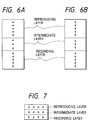
- a third magnetic layer will be referred to as an intermediate layer hereinafter. Therefore, the basic structure of the magnetic layers of the magneto-optical recording medium of the present invention is realized by stacking the reproducing layer, the intermediate layer, and the recording layer, as shown in Fig. 3.
- the reproducing layer As the material of the reproducing layer, a rare earth-iron group amorphous alloy such as GdFeCo, GdCo, GdTbFeCo, GdDyFeCo, or the like is preferable.
- the reproducing layer In order to obtain a sufficient magneto-optical effect upon reproduction, the reproducing layer is required to a high Curie temperature, and preferably has a Curie temperature of 250°C and, more preferably, 300°C or higher.
- a light rare earth element such as Nd, Sm, Pr, or the like may be added.
- a rare earth-iron group amorphous alloy such as GdFeCo, GdCo, GdTbFeCo, GdDyFeCo, or the like is preferable.
- the Curie temperature of the intermediate layer is equal to or higher than room temperature, and preferably falls within a range from 100°C to 250°C and, more preferably, a range from 130°C to 210°C.
- a film which has large perpendicular magnetic anisotropy and can stably hold a magnetization state e.g., a rare earth-iron group amorphous alloy film consisting of, e.g., TbFeCo, DyFeCo, TbDyFeCo, or the like; a garnet film; a platinum group-iron group periodic structure film such as Pt/Co, Pd/Co, or the like; a platinum group-iron group alloy film consisting of, e.g., PtCo, PdCo, or the like; or the like is preferable.
- a rare earth-iron group amorphous alloy film consisting of, e.g., TbFeCo, DyFeCo, TbDyFeCo, or the like
- a garnet film e.g., a platinum group-iron group periodic structure film such as Pt/Co, Pd/Co, or the like
- the recording layer is required to allow recording with a laser power as low as possible, and to stably hold a recorded magnetic domain at room temperature and the reproducing temperature, as minimum requirements.
- the recording layer preferably has a large perpendicular magnetic anisotropy and a low Curie temperature.
- the Curie temperature must be set to be equal to or higher than the reproducing temperature.
- the reproducing layer is required to be an in-plane magnetization film at room temperature and to be a perpendicular magnetization film at high temperatures.
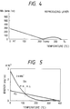
- a reproducing layer which consists of a ferrimagnetic heavy rare earth-iron group transition metal alloy, has a compensation temperature between room temperature and its Curie temperature, has large Ms at room temperature and small Ms at the reproducing temperature, as shown in Fig. 4, may be used.
- the reproducing layer consists of GdFeCo
- the Gd content preferably falls within a range from 22 to 38%, and more preferably, a range from 25 to 35%.
- the above-mentioned energy Ku apparently changes when another magnetic film is stacked on the magnetic thin film of interest. This is because a magnetic coupling force such as an exchange coupling force, magnetostatic coupling force, or the like acts from the other stacked magnetic layer. For example, when a perpendicular magnetization film is stacked on the magnetic thin film of interest, Ku apparently increases; when an in-plane magnetization film is stacked, Ku apparently decreases.
- a magnetic coupling force such as an exchange coupling force, magnetostatic coupling force, or the like acts from the other stacked magnetic layer.
- the intermediate layer is arranged between the reproducing layer and the recording layer.
- the intermediate layer is an in-plane magnetization film which has a larger in-plane magnetic anisotropy than that of the reproducing layer at room temperature, and is a magnetic film which has perpendicular magnetic anisotropy or a small in-plane magnetic anisotropy at the reproducing temperature.
- the apparent Ku of the reproducing layer decreases at room temperature.
- the reproducing layer can stably become an in-plane magnetization film. Therefore, the reproducing layer can perfectly mask magnetization information on the recording layer.
- the reproducing layer at the reproducing temperature, as shown in Fig. 6B, the reproducing layer stably becomes a perpendicular magnetization film, and can sufficiently reproduce magnetization information on the recording layer.
- the in-plane anisotropy, at room temperature, of the intermediate layer is larger than that, at room temperature, of the reproducing layer.
- Ms at room temperature can be increased.
- the perpendicular anisotropy energy Ku may be decreased or may be controlled to assume a negative value (to have in-plane anisotropy) by, e.g., adding an element such as Co for improving in-plane anisotropy.
- the intermediate layer consists of GdFe as a major component, the Gd content preferably falls within a range from 35 to 50% and, more preferably, a range from 40 to 47%.
- the intermediate layer need not contribute to the magneto-optical effect, the reproducing characteristics do not deteriorate even when the Curie temperature of the intermediate layer is set to be low. Therefore, in order to increase the perpendicular magnetic anisotropy, at the reproducing temperature, of the intermediate layer, for example, the Curie temperature of the reproducing layer may be set to be lower than that of the reproducing layer, so that Ms sufficiently becomes small at the reproducing layer.
- the Curie temperature can be lowered by adding a non-magnetic element such as Al, Si, Cu, or the like, or by decreasing the Co content.
- the intermediate layer can be provided with perpendicular magnetic anisotropy by the magnetic coupling forces from the recording layer and the reproducing layer which has perpendicular magnetic anisotropy, and magnetization information on the recording layer can be transferred to the reproducing layer.
- the film thickness of the intermediate layer can be equal to or larger than that of a magnetic wall portion formed between the reproducing layer which is an in-plane magnetization film in a temperature range from room temperature to a temperature lower than the reproducing temperature, and the recording layer which is a perpendicular magnetization film.
- the film thickness of the intermediate layer preferably falls within a range from 20 ⁇ to 200 ⁇ and, more preferably, a range from 50 ⁇ to 150 ⁇ .
- the direction of magnetization of the reproducing layer can be easily aligned in the in-plane direction at room temperature as compared to a case wherein the reproducing layer is directly stacked on the recording layer.
- the magneto-optical recording medium of the present invention satisfies the following inequality III at room temperature: K ⁇ 3 ⁇ K ⁇ 1 ⁇ K ⁇ 2
- the Curie temperatures must satisfy the following inequality VI: RT (room temperature) ⁇ Tc3 ⁇ Tc1
- the magneto-optical recording medium of the present invention basically has a three-layered magnetic film structure.
- other magnetic layers may be arranged.
- a dielectric layer and a metal layer may be arranged.
- a metal thermal conductor layer may be arranged.
- the corrosion resistance may be increased.
- a data signal is recorded on the recording layer of the magneto-optical recording medium of the present invention, as shown in Fig. 7.
- Recording is attained by modulating an external magnetic field while applying a laser beam with a power which can increase the temperature of a recording layer portion to a temperature near its Curie temperature, or an overwrite operation is performed by modulating a laser power while applying a magnetic field in the recording direction after the direction of magnetization is erased by alignment in one direction using an initialization layer or an initialization magnetic field.
- the intensity of the laser beam is determined in consideration of the linear velocity of the recording medium, so that only a predetermined region in a light spot has a temperature near the Curie temperature of the recording layer, a recorded magnetic domain equal to or smaller than the diameter of the light spot can be formed, and as a result, a signal having a period equal to or smaller than the diffraction limit of light can be recorded.
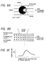
- a reproducing laser beam is continuously irradiated onto the medium, and light reflected by the medium is detected. At this time, the temperature of the laser irradiated portion rises, and the temperature distribution on the medium extends in the moving direction of the medium and includes a high-temperature portion in a portion in the light spot.
- the intensity of the reproducing laser beam is set so that the temperature of the portion in the light spot shown in Fig. 8C becomes equal to or higher than the temperature Tth at which the portion transits from an in-plane magnetization film to a perpendicular magnetization film
- the reproducing and recording layer portions corresponding to the portion in the light spot can become a perpendicular magnetization film (aperture region), as shown in Fig. 8B, and the remaining portion can remain to be an in-plane magnetization film (mask region). Since most of the interface magnetic wall formed between the reproducing layer and the recording layer is formed in the intermediate layer, the reproducing layer portion stably becomes an in-plane magnetization film.
- the reproducing layer portion which has become a perpendicular magnetization film is magnetically coupled by exchange coupling to the recording layer portion via the intermediate layer, a signal (information) on the recording layer portion is transferred to the reproducing layer portion.
- the transferred magnetic signal is converted into an optical signal by the magneto-optical effect (Kerr rotation angle or Faraday rotation angle) of the reproducing layer, and the optical signal is detected. More specifically, the information is reproduced by detecting reflected light.
- a signal recorded on the recording layer and having a period equal to or smaller than the diffraction limit of light can be transferred to the reproducing layer in units of recorded marks, and as a result, the signal having the period equal to or smaller than the diffraction limit of light can be reproduced without any intersymbol interference.
- a signal recorded on the recording layer portion of the neighboring track can be prevented from being transferred to the reproducing layer portion, and crosstalk can be eliminated, thus improving the track density.
- Fig. 9 shows this state.
- the reproducing layer and the recording layer are magnetically coupled to each other by the exchange interaction.
- the recording layer and the reproducing layer may be magnetically coupled to each other by magnetostatic coupling upon reproduction.
- Si, Gd, Tb, Fe, and Co targets were attached to a DC magnetron sputtering apparatus, and a glass substrate having a diameter of 130 mm and a polycarbonate substrate with pregrooves were fixed to a substrate holder arranged at a position separated from the targets by a distance of 150 mm. Thereafter, the interior of a chamber was evacuated by a cryopump to a high vacuum of 1 ⁇ 10 ⁇ 5 Pa or less.
- the composition of the GdFeCo reproducing layer was selected to be RE rich at room temperature, and to have a saturation magnetization Ms of 160 emu/cc, a compensation temperature of 205°C, and a Curie temperature of 300°C or higher.
- the composition of the GdFe intermediate layer was selected to be TM rich at room temperature, and to have Ms of 450 emu/cc and a Curie temperature of 205°C.
- the composition of the TbFeCo recording layer was selected to be TM rich at room temperature, and to have a saturation magnetization Ms of 200 emu/cc and a Curie temperature of 220°C.
- a semiconductor laser beam of 830 nm was irradiated onto the sample which was formed on the glass substrate, as described above, from the glass substrate side, and the external magnetic field dependence of the Kerr rotation angle ( ⁇ K ) was measured.
- the measurement was performed by heating the sample from room temperature to about 200°C.
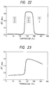
- the temperature dependence of the Kerr rotation angle (residual Kerr rotation angle; ⁇ K R ) obtained when the external magnetic field was zero is represented by a curve (A) in the graph of Fig. 12.
- ⁇ K R is zero within a temperature range from room temperature to about 140°C, and thereafter, ⁇ K R abruptly increases.
- the recording/reproduction characteristics were then measured using this magneto-optical recording medium.
- the N.A. of an objective lens was set to be 0.55
- the laser wavelength was set to be 780 nm
- the recording power fell within the range from 7 to 13 mW
- the reproducing power fell within a range from 2.5 to 3.5 mW, so as to obtain the highest C/N ratio.
- the linear velocity was set to be 9 m/s.
- a carrier signal of 5 to 15 MHz was recorded on the recording layer, and the recording mark dependence of the C/N ratio was checked. Then, crosstalk was measured. The crosstalk was expressed as a difference between a reproducing signal obtained from a land portion on which a signal with a mark length of 1.6 ⁇ m was recorded, and a reproducing signal obtained from a neighboring groove portion. Table 1 shows the measurement results.
- the composition of the GdFeCo reproducing layer was selected to be RE rich at room temperature, and to have a saturation magnetization Ms of 180 emu/cc, a compensation temperature of 220°C, and a Curie temperature of 300°C or higher.
- the composition of the GdFe intermediate layer was selected to be RE rich at room temperature, and to have Ms of 390 emu/cc and a Curie temperature of 210°C.
- the composition of the TbFeCo recording layer was selected to be TM rich at room temperature, and to have a saturation magnetization Ms of 200 emu/cc and a Curie temperature of 220°C.
- the composition of the GdFeCo reproducing layer was selected to be RE rich at room temperature, and to have a saturation magnetization Ms of 130 emu/cc, a compensation temperature of 188°C, and a Curie temperature of 300°C or higher.
- the composition of the GdFe intermediate layer was selected to be RE rich at room temperature, and to have Ms of 540 emu/cc and a Curie temperature of 200°C.
- the composition of the TbFeCo recording layer was selected to be TM rich at room temperature, and to have a saturation magnetization Ms of 200 emu/cc and a Curie temperature of 220°C.
- the composition of the GdFeCo reproducing layer was selected to be RE rich at room temperature, and to have a saturation magnetization Ms of 130 emu/cc, a compensation temperature of 188°C, and a Curie temperature of 300°C or higher.
- the composition of the GdFe intermediate layer was selected to be RE rich at room temperature, and to have Ms of 480 emu/cc and a Curie temperature of 215°C.
- the composition of the TbFeCo recording layer was selected to be TM rich at room temperature, and to have a saturation magnetization Ms of 200 emu/cc and a Curie temperature of 220°C.
- the composition of the GdFeCo reproducing layer was selected to be RE rich at room temperature, and to have a saturation magnetization Ms of 130 emu/cc, a compensation temperature of 188°C, and a Curie temperature of 300°C or higher.
- the composition of the TbFeCo recording layer was selected to be TM rich at room temperature, and to have a saturation magnetization Ms of 200 emu/cc and a Curie temperature of 220°C.
- the magneto-optical recording medium of Experimental Example 1 can improve in-plane magnetic anisotropy on a low-temperature portion near room temperature while maintaining a state wherein a perpendicular magnetization film is obtained at high temperatures.
- a 900- ⁇ thick SiN dielectric layer, a 400- ⁇ thick GdFeCo reproducing layer, a 400- ⁇ TbFeCo recording layer, and a 700- ⁇ thick SiN protective layer were formed on a polycarbonate substrate in the order named to obtain a magneto-optical recording medium.
- the refractive index of each SiN layer was selected to be 2.1.
- the composition of the GdFeCo reproducing layer was selected to be RE rich at room temperature, and to have a saturation magnetization Ms of 180 emu/cc, a compensation temperature of 220°C, and a Curie temperature of 300°C or higher.
- the composition of the TbFeCo recording layer was selected to be TM rich at room temperature, and to have a saturation magnetization Ms of 200 emu/cc and a Curie temperature of 220°C.
- a 900- ⁇ thick SiN dielectric layer, a 400- ⁇ thick GdFeCo reproducing layer, a 400- ⁇ TbFeCo recording layer, and a 700- ⁇ thick SiN protective layer were formed on a polycarbonate substrate in the order named to obtain a magneto-optical recording medium.
- the refractive index of each SiN layer was selected to be 2.1.
- the composition of the GdFeCo reproducing layer was selected to be RE rich at room temperature, and to have a saturation magnetization Ms of 270 emu/cc, a compensation temperature of 280°C, and a Curie temperature of 300°C or higher.
- the composition of the TbFeCo recording layer was selected to be TM rich at room temperature, and to have a saturation magnetization Ms of 200 emu/cc and a Curie temperature of 220°C.
- the magneto-optical recording medium and the reproducing method of the present invention are used, a magnetic domain smaller than the beam spot size can be reproduced using a simple apparatus (conventional apparatus) having no initialization magnet, and crosstalk can be eliminated, thus achieving high-density recording with a remarkably improved line recording density and track density.
- a magneto-optical recording medium and a reproducing method using the medium according to the second embodiment of the present invention will be described below with reference to the accompanying drawings.
- a first magnetic layer will be referred to as a reproducing layer hereinafter
- a second magnetic layer will be referred to as a recording layer hereinafter
- a third magnetic layer will be referred to as an intermediate layer hereinafter.
- the magneto-optical recording medium of the present invention comprises at least three layers, i.e., a reproducing layer which is an in-plane magnetization film at room temperature, changes to a perpendicular magnetization film when the temperature rises, and then becomes an in-plane magnetization film or loses its magnetization when the temperature further rises, a recording layer which is a perpendicular magnetization film at room temperature and at high temperatures, and an intermediate layer which has a larger in-plane anisotropy at a temperature near room temperature than that of the reproducing layer.
- a reproducing layer which is an in-plane magnetization film at room temperature, changes to a perpendicular magnetization film when the temperature rises, and then becomes an in-plane magnetization film or loses its magnetization when the temperature further rises
- a recording layer which is a perpendicular magnetization film at room temperature and at high temperatures
- an intermediate layer which has a larger in-plane anisotropy at a temperature near room temperature than that of
- the reproducing layer preferably has a small magnetic anisotropy, and has a compensation temperature between room temperature and its Curie temperature.
- a film which has large perpendicular magnetic anisotropy and can stably hold a magnetization state e.g., a rare earth-iron group amorphous alloy film consisting of, e.g., TbFeCo, DyFeCo, TbDyFeCo, or the like; a garnet film; a platinum group-iron group periodic structure film such as Pt/Co, Pd/Co, or the like; a platinum group-iron group alloy film consisting of, e.g., PtCo, PdCo, or the like; or the like is preferable.
- An element for improving corrosion resistance such as Cr, Al, Ti, Pt, Nb, or the like may be added to the magnetic layers such as the reproducing layer, the recording layer, and the like.
- a dielectric layer consisting of, e.g., SiN x , AlN x , TaO x , SiO x , or the like may be arranged to enhance the interference effect.
- a layer consisting of Al, AlTa, AlTi, AlCr, Cu, or the like may be arranged.
- an auxiliary layer may be arranged for the purpose of helping recording and reproduction.
- a protective layer a dielectric layer or a protective coat consisting a polymer resin may be added.
- the recording/reproducing method of the magneto-optical recording medium according to the second embodiment of the present invention will be explained below. However, since the recording method is the same as that in the first embodiment described above, a detailed description thereof will be omitted.
- the basic principle of the reproducing method of a magneto-optical recording method in the second embodiment of the present invention will be explained below using a basic two-layered medium comprising a reproducing layer and a recording layer. This principle is also applicable to a case wherein an intermediate layer is arranged, as a matter of course.
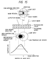
- a state wherein the magnetization of the reproducing layer in the highest-temperature portion and low-temperature portion as portions of a light spot becomes an in-plane magnetization film, and the magnetization of the reproducing layer in a portion at a middle temperature therebetween is a perpendicular magnetization film is realized. Since the reproducing layer portion as a perpendicular magnetization film is magnetically coupled to the recording layer by exchange coupling, the direction of magnetization of this reproducing layer portion follows a stable direction in relation to the direction of magnetization based on information on the recording layer. More specifically, the information recorded on the recording layer is transferred to the reproducing layer.
- the transferred information is converted into an optical signal by the magneto-optical effect (in other words, the magneto-optical effect (polar Kerr effect) of a laser beam reflected by the reproducing layer) of the reproducing layer, and the optical signal is detected. That is, the information is reproduced by detecting the reflected light.
- the magneto-optical effect in other words, the magneto-optical effect (polar Kerr effect) of a laser beam reflected by the reproducing layer
- the optical signal is detected. That is, the information is reproduced by detecting the reflected light.
- no magneto-optical effect polar Kerr effect
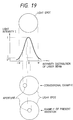
- a mask region which masks magnetization information on the recording layer, and an aperture region through which the magnetization information is detected are formed in the light spot. Since the aperture region can have an area smaller than that of the light spot, a signal having a period equal to or smaller than the diffraction light of light can be detected, and the line density can be increased.
- the reproducing layer and the recording layer are magnetically coupled to each other by the exchange interaction.
- the recording layer and the reproducing layer may be magnetically coupled to each other by magnetostatic coupling upon reproduction.
- an exchange coupling force, a magnetostatic coupling force, or the like from the perpendicular magnetization film acts, and Ku apparently increases. For this reason, the temperature region which has perpendicular magnetization is shifted toward the low temperature side as compared to a case wherein the layers are not stacked.
- the perpendicular magnetization temperature region as a single-layered film is set to be relatively high, even when such a film is stacked on a perpendicular magnetization film, a situation that the film becomes an in-plane magnetization film at room temperature and high temperatures, and becomes a perpendicular magnetization film on only a middle temperature region therebetween is established.
- a mask may be formed on the highest-temperature portion by causing the magnetization of the reproducing layer to disappear.
- Tc of the reproducing layer since the Curie temperature Tc of the reproducing layer must be set to be lower than Tc of the recording layer, the signal strength upon reproduction is slightly lowered.
- the intermediate layer in the magneto-optical recording medium according to the second embodiment of the present invention will be explained in more detail below.
- the intermediate layer is located between the reproducing layer and the recording layer, and must have a larger in-plane anisotropy than that of the reproducing layer near room temperature.
- in-plane anisotropy when, for example, a rare earth-iron group alloy is used, a rare earth element dominant composition or an iron element dominant composition can be adopted to increase Ms, at room temperature, of the intermediate layer.
- the Curie temperature of the intermediate layer is higher than the room temperature and is lower than those of the reproducing layer and the recording layer.
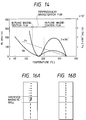
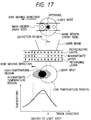
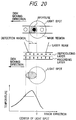
- an interface magnetic wall can be confined in the intermediate layer from room temperature up to an aperture region, as shown in Figs. 16A and 16B.
- the reproducing layer can stably be an in-plane magnetization film on a low-temperature region, and can perfectly mask magnetization information on the recording layer.
- the Curie temperature of the intermediate layer is set to be lower than that of the recording layer and to be high so as not to disconnect exchange coupling between the reproducing layer and the recording layer on a middle-temperature region in the light spot, Ms of the intermediate layer can be sufficiently small on the middle-temperature region, thus weakening in-plane anisotropy and strengthening perpendicular magnetic anisotropy. Even when the intermediate layer itself does not have any perpendicular magnetic anisotropy at the reproducing temperature, the intermediate layer can be imparted perpendicular magnetic anisotropy by a magnetic coupling force from the recording layer and the reproducing layer, whose temperature has risen to have perpendicular magnetic anisotropy.
- the magnetization on the recording layer is transferred to the reproducing layer.
- the temperature of the intermediate layer since the temperature of the intermediate layer has reached its Curie temperature, and the exchange coupling force does not act between the recording layer and the reproducing layer, it is ease for the reproducing layer portion to become an in-plane magnetization film.
- a mask region which masks magnetization information on the recording layer, and an aperture region through which the magnetization information is detected are formed in the light spot. Since the aperture region can have an area smaller than that of the light spot, a signal having a period equal to or smaller than the diffraction light of light can be detected. As described above, the front-side mask can have a perfect function.
- the intermediate layer preferably consists of a material such as Gd or the like which has a small anisotropy and can easily form an interface magnetic wall, for example, GdFe, GeFeCo, or the like, and a non-magnetic element such as Al, Cu, Cr, or the like is preferably added to such a material so as to decrease the Curie temperature.
- the film thickness of the intermediate layer can be equal to or larger than that of a magnetic wall portion formed between the reproducing layer which is an in-plane magnetization film in a temperature range from room temperature to a temperature lower than the reproducing temperature, and the recording layer which is a perpendicular magnetization film.
- the film thickness of the intermediate layer preferably falls within a range from 20 ⁇ to 200 ⁇ and, more preferably, a range from 50 ⁇ to 150 ⁇ .
- the compensation temperature of the reproducing layer is represented by T comp1
- the saturation magnetizations of the reproducing layer, intermediate layer, and recording layer are respectively represented by Ms1, Ms3, and Ms2
- the effective perpendicular magnetic anisotropy constants of the reproducing layer, intermediate layer, and recording layer are respectively represented by K ⁇ 1, K ⁇ 3, and K ⁇ 2
- Figs. 18A to 18C show an example of the temperature dependences of the saturation magnetizations of the reproducing layer, intermediate layer, and recording layer, which can satisfy the above-mentioned conditions.
- the perpendicular anisotropy energy Ku may be set to be small or may assume a negative value (to have in-plane anisotropy) by, e.g., adding an element such as Co for improving in-plane anisotropy.
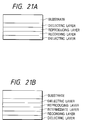
- a 900- ⁇ thick SiN dielectric layer, a 400- ⁇ thick GdFeCo reproducing layer, a 100- ⁇ thick GdFe intermediate layer, a 300- ⁇ thick TbFeCo recording layer, and a 700- ⁇ thick SiN protective layer were formed on a glass substrate in the order named to obtain a sample with the arrangement shown in Fig. 21B.
- N2 gas was supplied in addition to Ar gas, and the film was formed by DC reactive sputtering. In this case, the mixing ratio of the Ar gas and N2 gas was adjusted to obtain a refractive index of 2.1.
- the composition of the GdFeCo reproducing layer was selected to be RE rich at room temperature, and to have a saturation magnetization Ms of 160 emu/cc, a compensation temperature of 205°C, and a Curie temperature of 300°C or higher.
- the composition of the GdFe intermediate layer was selected to be RE rich at room temperature, and to have Ms of 520 emu/cc and a Curie temperature of 150°C.
- the composition of the TbFeCo recording layer was selected to be TM rich at room temperature, and to have a saturation magnetization Ms of 200 emu/cc and a Curie temperature of 220°C.
- ⁇ K Kerr rotation angle
- Magneto-optical recording films were formed on a polycarbonate substrate with pregrooves to have the same layer arrangement and film compositions as those in Experimental Example 5, thus manufacturing a magneto-optical recording medium of the present invention.
- the N.A. of an objective lens was set to be 0.55, and the laser wavelength was set to be 780 nm.
- the recording power was set to be 8 mW and the linear velocity to be 9 m/s
- carrier signals of 6 to 15 MHz were written stepwise on the recording layer by a magnetic field modulation method while applying a magnetic field of ⁇ 200 Oe, and then, the recording mark length dependence of the C/N ratio was checked.
- the reproducing power was set to be a value (2.5 to 3.5 mW) which could maximize the C/N ratio.
- crosstalk from neighboring tracks was measured.
- the crosstalk was expressed as a difference between a reproducing signal obtained from a land portion on which a signal with a mark length of 1.6 ⁇ m was recorded, and a reproducing signal obtained from a neighboring groove portion.
- Table 2 shows the measurement results.
- a 900- ⁇ thick SiN dielectric layer, a 400- ⁇ thick GdFeCo reproducing layer, a 120- ⁇ thick GdFe intermediate layer, a 300- ⁇ TbFeCo recording layer, and a 700- ⁇ thick SiN protective layer were formed on a polycarbonate substrate in the order named to obtain a sample with the arrangement shown in Fig. 21B.
- the composition of the GdFeCo reproducing layer was selected to be RE rich at room temperature, and to have a saturation magnetization Ms of 180 emu/cc, a compensation temperature of 220°C, and a Curie temperature of 300°C or higher.
- the composition of the GdFe intermediate layer was selected to be RE rich at room temperature, and to have Ms of 680 emu/cc and a Curie temperature of 180°C.
- the composition of the TbFeCo recording layer was selected to be TM rich at room temperature, and to have a saturation magnetization Ms of 200 emu/cc and a Curie temperature of 220°C.
- a 900- ⁇ thick SiN dielectric layer, a 400- ⁇ thick GdFeCo reproducing layer, an 80- ⁇ thick GdFe intermediate layer, a 300- ⁇ TbFeCo recording layer, and a 700- ⁇ thick SiN protective layer were formed on a polycarbonate substrate in the order named to obtain a sample with the arrangement shown in Fig. 21B.
- the composition of the GdFeCo reproducing layer was selected to be RE rich at room temperature, and to have a saturation magnetization Ms of 150 emu/cc, a compensation temperature of 188°C, and a Curie temperature of 300°C or higher.
- the composition of the GdFe intermediate layer was selected to be RE rich at room temperature, and to have Ms of 520 emu/cc and a Curie temperature of 170°C.
- the composition of the TbFeCo recording layer was selected to be TM rich at room temperature, and to have a saturation magnetization Ms of 200 emu/cc and a Curie temperature of 220°C.
- a 900- ⁇ thick SiN dielectric layer, a 400- ⁇ thick GdFeCo reproducing layer, a 90- ⁇ thick GdFe intermediate layer, a 300- ⁇ TbFeCo recording layer, and a 700- ⁇ thick SiN protective layer were formed on a polycarbonate substrate in the order named to obtain a sample with the arrangement shown in Fig. 21B.
- the composition of the GdFeCo reproducing layer was selected to be RE rich at room temperature, and to have a saturation magnetization Ms of 160 emu/cc, a compensation temperature of 188°C, and a Curie temperature of 300°C or higher.
- the composition of the GdFe intermediate layer was selected to be RE rich at room temperature, and to have Ms of 470 emu/cc and a Curie temperature of 165°C.
- the composition of the TbFeCo recording layer was selected to be TM rich at room temperature, and to have a saturation magnetization Ms of 200 emu/cc and a Curie temperature of 220°C.
- the composition of the GdFeCo reproducing layer was selected to be RE rich at room temperature, and to have a saturation magnetization Ms of 130 emu/cc, a compensation temperature of 280°C, and a Curie temperature of about 300°C.
- the composition of the TbFeCo recording layer was selected to be TM rich at room temperature, and to have a saturation magnetization Ms of 200 emu/cc and a Curie temperature of 220°C.
- This sample had temperature dependence of the residual ⁇ K R , as shown in Fig. 23, and did not revert to an in-plane magnetization film again at high temperatures.
- the compensation temperature is close to the Curie temperature like in this comparative experimental example, the reproducing layer cannot be an in-plane magnetization film again at high temperatures.
- a 900- ⁇ thick SiN dielectric layer, a 400- ⁇ thick GdFeCo reproducing layer, a 300- ⁇ TbFeCo recording layer, and a 700- ⁇ thick SiN protective layer were formed on a polycarbonate substrate in the order named to obtain a magneto-optical recording medium of the present invention with the arrangement shown in Fig. 21A.
- Each SiN layer had a refractive index of 2.1.
- the composition of the GdFeCo reproducing layer was selected to be RE rich at room temperature, and to have a saturation magnetization Ms of 180 emu/cc, a compensation temperature of 290°C, and a Curie temperature of about 300°C.
- the composition of the TbFeCo recording layer was selected to be TM rich at room temperature, and to have a saturation magnetization Ms of 200 emu/cc and a Curie temperature of 220°C.
Applications Claiming Priority (6)
| Application Number | Priority Date | Filing Date | Title |
|---|---|---|---|
| JP2265394A JPH06309729A (ja) | 1993-02-26 | 1994-02-21 | 光磁気記録媒体及び該媒体を用いた情報再生方法 |
| JP22653/94 | 1994-02-21 | ||
| JP2265394 | 1994-02-21 | ||
| JP45594/94 | 1994-03-16 | ||
| JP4559494A JPH07254176A (ja) | 1994-03-16 | 1994-03-16 | 光磁気記録媒体および該媒体を用いた情報再生方法 |
| JP4559494 | 1994-03-16 |
Publications (3)
| Publication Number | Publication Date |
|---|---|
| EP0668586A2 true EP0668586A2 (fr) | 1995-08-23 |
| EP0668586A3 EP0668586A3 (fr) | 1996-03-06 |
| EP0668586B1 EP0668586B1 (fr) | 2002-05-02 |
Family
ID=26359918
Family Applications (1)
| Application Number | Title | Priority Date | Filing Date |
|---|---|---|---|
| EP95301061A Expired - Lifetime EP0668586B1 (fr) | 1994-02-21 | 1995-02-20 | Support d'enregistrement magnéto-optique et méthode de reproduction faisant usage de ce support |
Country Status (6)
| Country | Link |
|---|---|
| US (2) | US5830589A (fr) |
| EP (1) | EP0668586B1 (fr) |
| KR (1) | KR950025656A (fr) |
| AU (1) | AU696024B2 (fr) |
| CA (1) | CA2142767C (fr) |
| DE (1) | DE69526532T2 (fr) |
Cited By (6)
| Publication number | Priority date | Publication date | Assignee | Title |
|---|---|---|---|---|
| EP0724260A1 (fr) * | 1994-12-27 | 1996-07-31 | Canon Kabushiki Kaisha | Milieu d'enregistrement magnéto-optique du type super-résolution avec une couche à magnétisation dans le plan et méthode de reproduction d'information utilisant le même milieu |
| EP0740296A3 (fr) * | 1995-04-26 | 1998-02-25 | Sanyo Electric Co. Ltd | Milieux d'enregistrement magnéto-optique |
| EP0785545A3 (fr) * | 1995-08-15 | 1998-06-17 | Canon Kabushiki Kaisha | Support d'enregistrement magnéto-optique et méthode de reproduction à partir d'un tel support |
| EP0822547A3 (fr) * | 1996-07-30 | 1998-09-09 | Sharp Kabushiki Kaisha | Support d'enregistrement magnéto-optique ainsi que Méthode de reproduction utilisant un tel support |
| US6062685A (en) * | 1994-12-26 | 2000-05-16 | Canon Kabushiki Kaisha | Sheet convey apparatus |
| EP0978833A3 (fr) * | 1998-08-07 | 2002-01-16 | Sony Corporation | Support d'enregistrement magnéto-opique et appareil d'enregistrement/lecture magnéto-optique |
Families Citing this family (14)
| Publication number | Priority date | Publication date | Assignee | Title |
|---|---|---|---|---|
| CA2142767C (fr) * | 1994-02-21 | 1998-11-17 | Naoki Nishimura | Support d'enregistrement magneto-optique et methode d'enregistrement d'informations utilisant ce support |
| JP3545133B2 (ja) * | 1996-07-23 | 2004-07-21 | シャープ株式会社 | 光磁気記録媒体の再生方法及び光磁気記録媒体 |
| JPH10269627A (ja) * | 1997-03-21 | 1998-10-09 | Toshiba Corp | 光記録媒体および超解像再生方法 |
| US6111784A (en) * | 1997-09-18 | 2000-08-29 | Canon Kabushiki Kaisha | Magnetic thin film memory element utilizing GMR effect, and recording/reproduction method using such memory element |
| JP3568787B2 (ja) * | 1998-09-08 | 2004-09-22 | シャープ株式会社 | 光磁気記録媒体及び再生装置 |
| US6603619B1 (en) * | 1999-01-07 | 2003-08-05 | Sharp Kabushiki Kaisha | Magnetic storage medium and heat assisted recording and reproduction method |
| JP3476698B2 (ja) * | 1999-01-29 | 2003-12-10 | シャープ株式会社 | 光磁気記録媒体 |
| US6519211B1 (en) * | 1999-04-01 | 2003-02-11 | Matsushita Electric Industrial Co., Ltd. | Magneto-optical recording medium having magnetic domain shrinks and disappears |
| JP3434242B2 (ja) * | 1999-07-29 | 2003-08-04 | シャープ株式会社 | 光磁気記録媒体及びその再生方法 |
| US7352658B2 (en) * | 2000-09-25 | 2008-04-01 | Hitachi Maxell, Ltd. | Method for recording information data to a recording medium by irradiation with a light beam and application of a magnetic field |
| US7035138B2 (en) | 2000-09-27 | 2006-04-25 | Canon Kabushiki Kaisha | Magnetic random access memory having perpendicular magnetic films switched by magnetic fields from a plurality of directions |
| JP2002334491A (ja) * | 2001-05-10 | 2002-11-22 | Fujitsu Ltd | 光磁気記録媒体 |
| AU2003244936A1 (en) * | 2002-07-05 | 2004-01-23 | Koninklijke Philips Electronics N.V. | Magneto-optical recording medium with anti-ferromagnetically coupled domain-expansion double-layer structure |
| TW200809845A (en) * | 2006-03-06 | 2008-02-16 | Ricoh Co Ltd | Optical recording medium, and method for initializing the optical recording medium |
Family Cites Families (21)
| Publication number | Priority date | Publication date | Assignee | Title |
|---|---|---|---|---|
| CA1326547C (fr) * | 1988-07-13 | 1994-01-25 | Masahiko Kaneko | Methode d'enregistrement thermomagnetique |
| US5094925A (en) * | 1989-06-30 | 1992-03-10 | Sharp Kabushiki Kaisha | Opto-magnetic recording medium |
| US5168482A (en) * | 1989-08-31 | 1992-12-01 | Sony Corporation | Magnetooptical recording and playback method employing multi-layer recording medium with record holding layer and playback layer |
| JP2910084B2 (ja) * | 1989-09-06 | 1999-06-23 | ソニー株式会社 | 光磁気記録媒体における信号再生方法 |
| JP2884617B2 (ja) * | 1989-09-08 | 1999-04-19 | ソニー株式会社 | 光磁気記録再生方法 |
| US5241520A (en) * | 1990-12-28 | 1993-08-31 | Sony Corporation | System and method of reproducing signals recorded on a magneto-optic recording medium |
| JP3106514B2 (ja) | 1991-02-08 | 2000-11-06 | ソニー株式会社 | 光磁気記録再生方法 |
| JP3111479B2 (ja) * | 1991-02-08 | 2000-11-20 | ソニー株式会社 | 光磁気記録媒体 |
| JP2620992B2 (ja) * | 1991-02-15 | 1997-06-18 | 松下電工株式会社 | 電子部品の半田付け部の検査方法 |
| JP2839783B2 (ja) * | 1991-04-17 | 1998-12-16 | シャープ株式会社 | 光磁気記録媒体、再生装置及び再生方法 |
| JP2812817B2 (ja) * | 1991-07-08 | 1998-10-22 | シャープ株式会社 | 光磁気記録媒体 |
| EP0818783A3 (fr) * | 1991-07-16 | 1999-04-14 | Canon Kabushiki Kaisha | Milieu d'enregistrement magnétooptique et méthode |
| JP2786360B2 (ja) * | 1991-12-05 | 1998-08-13 | シャープ株式会社 | 光磁気ディスク |
| EP1143434A3 (fr) * | 1992-08-28 | 2001-12-12 | Canon Kabushiki Kaisha | Support d'enregistrement magnéto-optique et procédés d'enregistrement et de reproduction des informations utilisant ce support d'enregistrement |
| JP2938284B2 (ja) * | 1992-10-06 | 1999-08-23 | シャープ株式会社 | 光磁気記録媒体及びこれを用いた記録再生方法 |
| JPH06162589A (ja) * | 1992-11-18 | 1994-06-10 | Ricoh Co Ltd | 光磁気記録媒体及び光磁気記録方法 |
| JP2999895B2 (ja) * | 1992-12-10 | 2000-01-17 | シャープ株式会社 | 光磁気記録媒体 |
| JP2857002B2 (ja) * | 1993-01-07 | 1999-02-10 | シャープ株式会社 | 光磁気記憶装置 |
| JP3072812B2 (ja) * | 1993-04-08 | 2000-08-07 | キヤノン株式会社 | 光磁気記録媒体及び該媒体の情報再生方法 |
| JP3078145B2 (ja) | 1993-04-23 | 2000-08-21 | キヤノン株式会社 | 光磁気記録媒体の製造方法 |
| CA2142767C (fr) * | 1994-02-21 | 1998-11-17 | Naoki Nishimura | Support d'enregistrement magneto-optique et methode d'enregistrement d'informations utilisant ce support |
-
1995
- 1995-02-17 CA CA002142767A patent/CA2142767C/fr not_active Expired - Fee Related
- 1995-02-20 AU AU12355/95A patent/AU696024B2/en not_active Ceased
- 1995-02-20 EP EP95301061A patent/EP0668586B1/fr not_active Expired - Lifetime
- 1995-02-20 DE DE69526532T patent/DE69526532T2/de not_active Expired - Fee Related
- 1995-02-21 US US08/391,563 patent/US5830589A/en not_active Expired - Lifetime
- 1995-02-21 KR KR1019950003305A patent/KR950025656A/ko not_active Ceased
-
1998
- 1998-03-23 US US09/045,682 patent/US6307816B1/en not_active Expired - Lifetime
Cited By (11)
| Publication number | Priority date | Publication date | Assignee | Title |
|---|---|---|---|---|
| US6062685A (en) * | 1994-12-26 | 2000-05-16 | Canon Kabushiki Kaisha | Sheet convey apparatus |
| EP0724260A1 (fr) * | 1994-12-27 | 1996-07-31 | Canon Kabushiki Kaisha | Milieu d'enregistrement magnéto-optique du type super-résolution avec une couche à magnétisation dans le plan et méthode de reproduction d'information utilisant le même milieu |
| US5732049A (en) * | 1994-12-27 | 1998-03-24 | Canon Kabushiki Kaisha | Magneto-optical recording medium of super-resolution type using in-plane magnetic layer, and information reproducing method using the same medium |
| EP0740296A3 (fr) * | 1995-04-26 | 1998-02-25 | Sanyo Electric Co. Ltd | Milieux d'enregistrement magnéto-optique |
| US5771211A (en) * | 1995-04-26 | 1998-06-23 | Sanyo Electric Co., Ltd. | Magneto-optical recording media having a reading layer with a specified range of temperature coefficients of a kerr rotation angle |
| EP0785545A3 (fr) * | 1995-08-15 | 1998-06-17 | Canon Kabushiki Kaisha | Support d'enregistrement magnéto-optique et méthode de reproduction à partir d'un tel support |
| US5879822A (en) * | 1995-08-15 | 1999-03-09 | Canon Kabushiki Kaisha | Magneto-optical recording medium using in-plane magnetization film and capable of reproducing at super-high resolution and method of reproducing for such medium |
| EP0822547A3 (fr) * | 1996-07-30 | 1998-09-09 | Sharp Kabushiki Kaisha | Support d'enregistrement magnéto-optique ainsi que Méthode de reproduction utilisant un tel support |
| US5955191A (en) * | 1996-07-30 | 1999-09-21 | Sharp Kabushiki Kaisha | Magneto-optical recording medium and a reproducing method using such a medium |
| EP0978833A3 (fr) * | 1998-08-07 | 2002-01-16 | Sony Corporation | Support d'enregistrement magnéto-opique et appareil d'enregistrement/lecture magnéto-optique |
| US6625090B1 (en) | 1998-08-07 | 2003-09-23 | Sony Corporation | Magneto-optical recording medium, and magneto-optical recording/reproducing apparatus |
Also Published As
| Publication number | Publication date |
|---|---|
| AU1235595A (en) | 1995-08-31 |
| DE69526532D1 (de) | 2002-06-06 |
| KR950025656A (ko) | 1995-09-18 |
| AU696024B2 (en) | 1998-08-27 |
| US5830589A (en) | 1998-11-03 |
| EP0668586A3 (fr) | 1996-03-06 |
| DE69526532T2 (de) | 2002-10-31 |
| CA2142767C (fr) | 1998-11-17 |
| EP0668586B1 (fr) | 2002-05-02 |
| CA2142767A1 (fr) | 1995-08-22 |
| US6307816B1 (en) | 2001-10-23 |
Similar Documents
| Publication | Publication Date | Title |
|---|---|---|
| US5616428A (en) | Magnetooptical recording medium and information recording and reproducing methods using the recording medium | |
| US6187460B1 (en) | Magneto-optical recording medium and method for reproducing information therein | |
| US5830589A (en) | Magneto-optical recording medium, and information reproducing method using the medium | |
| EP0618572A2 (fr) | Support d'enregistrement magnéto-optique sur lequel il est possible d'enregistrer des informations en haute densité et procédé de reproduction des informations enrégistrées | |
| US6272077B1 (en) | Magneto-optical recording medium having intermediate layer of in plane magnetization | |
| US5862105A (en) | Information recording method capable of verifying recorded information simultaneously with recording, and magneto-optical recording medium used in the method | |
| US5790513A (en) | Magneto-optical recording medium capable of super resolution reproduction and information reproduction method using the same | |
| JP3078145B2 (ja) | 光磁気記録媒体の製造方法 | |
| US5719829A (en) | Magnetooptical recording medium allowing super-resolution, and information reproduction method using the medium | |
| EP0706181A1 (fr) | Milieu d'enregistrement magnéto-optique et méthode de reproduction d'information utilisant le milieu | |
| JPH06124500A (ja) | 光磁気記録媒体及び該媒体の再生方法 | |
| EP0668585B1 (fr) | Méthode et système d'enregistrement d'information utilisant un milieu d'enregistrement magnétooptique | |
| KR100271114B1 (ko) | 초 해상도의 광자기 기록 매체 및 이 매체를 이용한 정보 재생 방법 | |
| EP0724260B1 (fr) | Milieu d'enregistrement magnéto-optique du type super-résolution avec une couche à magnétisation dans le plan et méthode de reproduction d'information utilisant le même milieu | |
| USRE38922E1 (en) | Magneto-optical recording medium and method for reproducing information from a magneto-optical recording medium having three layers | |
| US5547773A (en) | Magnetooptic recording medium | |
| USRE38501E1 (en) | Magnetooptical recording medium and information recording and reproducing methods using the recording medium | |
| JPH07254176A (ja) | 光磁気記録媒体および該媒体を用いた情報再生方法 | |
| JP3101462B2 (ja) | 光磁気記録媒体及び該媒体を用いた情報再生方法 | |
| JPH06309729A (ja) | 光磁気記録媒体及び該媒体を用いた情報再生方法 | |
| JPH06309716A (ja) | 光磁気記録媒体及び該媒体の再生方法 |
Legal Events
| Date | Code | Title | Description |
|---|---|---|---|
| PUAI | Public reference made under article 153(3) epc to a published international application that has entered the european phase |
Free format text: ORIGINAL CODE: 0009012 |
|
| AK | Designated contracting states |
Kind code of ref document: A2 Designated state(s): DE FR GB IT NL |
|
| PUAL | Search report despatched |
Free format text: ORIGINAL CODE: 0009013 |
|
| AK | Designated contracting states |
Kind code of ref document: A3 Designated state(s): DE FR GB IT NL |
|
| 17P | Request for examination filed |
Effective date: 19960717 |
|
| 17Q | First examination report despatched |
Effective date: 19990302 |
|
| GRAG | Despatch of communication of intention to grant |
Free format text: ORIGINAL CODE: EPIDOS AGRA |
|
| GRAG | Despatch of communication of intention to grant |
Free format text: ORIGINAL CODE: EPIDOS AGRA |
|
| GRAG | Despatch of communication of intention to grant |
Free format text: ORIGINAL CODE: EPIDOS AGRA |
|
| GRAH | Despatch of communication of intention to grant a patent |
Free format text: ORIGINAL CODE: EPIDOS IGRA |
|
| REG | Reference to a national code |
Ref country code: GB Ref legal event code: IF02 |
|
| GRAH | Despatch of communication of intention to grant a patent |
Free format text: ORIGINAL CODE: EPIDOS IGRA |
|
| GRAA | (expected) grant |
Free format text: ORIGINAL CODE: 0009210 |
|
| AK | Designated contracting states |
Kind code of ref document: B1 Designated state(s): DE FR GB IT NL |
|
| REG | Reference to a national code |
Ref country code: GB Ref legal event code: FG4D |
|
| REF | Corresponds to: |
Ref document number: 69526532 Country of ref document: DE Date of ref document: 20020606 |
|
| ET | Fr: translation filed | ||
| PLBE | No opposition filed within time limit |
Free format text: ORIGINAL CODE: 0009261 |
|
| STAA | Information on the status of an ep patent application or granted ep patent |
Free format text: STATUS: NO OPPOSITION FILED WITHIN TIME LIMIT |
|
| 26N | No opposition filed |
Effective date: 20030204 |
|
| PGFP | Annual fee paid to national office [announced via postgrant information from national office to epo] |
Ref country code: NL Payment date: 20090217 Year of fee payment: 15 Ref country code: DE Payment date: 20090228 Year of fee payment: 15 |
|
| PGFP | Annual fee paid to national office [announced via postgrant information from national office to epo] |
Ref country code: GB Payment date: 20090218 Year of fee payment: 15 |
|
| PGFP | Annual fee paid to national office [announced via postgrant information from national office to epo] |
Ref country code: IT Payment date: 20090205 Year of fee payment: 15 |
|
| PGFP | Annual fee paid to national office [announced via postgrant information from national office to epo] |
Ref country code: FR Payment date: 20090223 Year of fee payment: 15 |
|
| REG | Reference to a national code |
Ref country code: NL Ref legal event code: V1 Effective date: 20100901 |
|
| GBPC | Gb: european patent ceased through non-payment of renewal fee |
Effective date: 20100220 |
|
| REG | Reference to a national code |
Ref country code: FR Ref legal event code: ST Effective date: 20101029 |
|
| PG25 | Lapsed in a contracting state [announced via postgrant information from national office to epo] |
Ref country code: NL Free format text: LAPSE BECAUSE OF NON-PAYMENT OF DUE FEES Effective date: 20100901 Ref country code: FR Free format text: LAPSE BECAUSE OF NON-PAYMENT OF DUE FEES Effective date: 20100301 |
|
| PG25 | Lapsed in a contracting state [announced via postgrant information from national office to epo] |
Ref country code: DE Free format text: LAPSE BECAUSE OF NON-PAYMENT OF DUE FEES Effective date: 20100901 |
|
| PG25 | Lapsed in a contracting state [announced via postgrant information from national office to epo] |
Ref country code: GB Free format text: LAPSE BECAUSE OF NON-PAYMENT OF DUE FEES Effective date: 20100220 Ref country code: IT Free format text: LAPSE BECAUSE OF NON-PAYMENT OF DUE FEES Effective date: 20100220 |