EP0668605A2 - Lampe à décharge à basse pression sans électrodes - Google Patents
Lampe à décharge à basse pression sans électrodes Download PDFInfo
- Publication number
- EP0668605A2 EP0668605A2 EP95100561A EP95100561A EP0668605A2 EP 0668605 A2 EP0668605 A2 EP 0668605A2 EP 95100561 A EP95100561 A EP 95100561A EP 95100561 A EP95100561 A EP 95100561A EP 0668605 A2 EP0668605 A2 EP 0668605A2
- Authority
- EP
- European Patent Office
- Prior art keywords
- cavity portion
- top surface
- lamp
- discharge lamp
- mantle
- Prior art date
- Legal status (The legal status is an assumption and is not a legal conclusion. Google has not performed a legal analysis and makes no representation as to the accuracy of the status listed.)
- Ceased
Links
- 239000000463 material Substances 0.000 claims abstract description 11
- OAICVXFJPJFONN-UHFFFAOYSA-N Phosphorus Chemical compound [P] OAICVXFJPJFONN-UHFFFAOYSA-N 0.000 claims abstract description 10
- 230000006698 induction Effects 0.000 claims abstract description 9
- 239000011248 coating agent Substances 0.000 claims abstract description 7
- 238000000576 coating method Methods 0.000 claims abstract description 7
- 239000000654 additive Substances 0.000 claims abstract description 5
- 230000000996 additive effect Effects 0.000 claims abstract description 5
- 229910052756 noble gas Inorganic materials 0.000 claims abstract description 4
- 239000010410 layer Substances 0.000 description 11
- 239000011247 coating layer Substances 0.000 description 3
- QSHDDOUJBYECFT-UHFFFAOYSA-N mercury Chemical compound [Hg] QSHDDOUJBYECFT-UHFFFAOYSA-N 0.000 description 3
- 229910052753 mercury Inorganic materials 0.000 description 3
- CPLXHLVBOLITMK-UHFFFAOYSA-N Magnesium oxide Chemical compound [Mg]=O CPLXHLVBOLITMK-UHFFFAOYSA-N 0.000 description 2
- VYPSYNLAJGMNEJ-UHFFFAOYSA-N Silicium dioxide Chemical compound O=[Si]=O VYPSYNLAJGMNEJ-UHFFFAOYSA-N 0.000 description 2
- GWEVSGVZZGPLCZ-UHFFFAOYSA-N Titan oxide Chemical compound O=[Ti]=O GWEVSGVZZGPLCZ-UHFFFAOYSA-N 0.000 description 2
- 239000011521 glass Substances 0.000 description 2
- 238000004519 manufacturing process Methods 0.000 description 2
- 230000001681 protective effect Effects 0.000 description 2
- 239000011241 protective layer Substances 0.000 description 2
- 238000012216 screening Methods 0.000 description 2
- XOLBLPGZBRYERU-UHFFFAOYSA-N tin dioxide Chemical compound O=[Sn]=O XOLBLPGZBRYERU-UHFFFAOYSA-N 0.000 description 2
- 229910000497 Amalgam Inorganic materials 0.000 description 1
- 229910052693 Europium Inorganic materials 0.000 description 1
- PXGOKWXKJXAPGV-UHFFFAOYSA-N Fluorine Chemical compound FF PXGOKWXKJXAPGV-UHFFFAOYSA-N 0.000 description 1
- DGAQECJNVWCQMB-PUAWFVPOSA-M Ilexoside XXIX Chemical compound C[C@@H]1CC[C@@]2(CC[C@@]3(C(=CC[C@H]4[C@]3(CC[C@@H]5[C@@]4(CC[C@@H](C5(C)C)OS(=O)(=O)[O-])C)C)[C@@H]2[C@]1(C)O)C)C(=O)O[C@H]6[C@@H]([C@H]([C@@H]([C@H](O6)CO)O)O)O.[Na+] DGAQECJNVWCQMB-PUAWFVPOSA-M 0.000 description 1
- 239000000853 adhesive Substances 0.000 description 1
- 230000001070 adhesive effect Effects 0.000 description 1
- 150000004645 aluminates Chemical class 0.000 description 1
- 229910052787 antimony Inorganic materials 0.000 description 1
- WATWJIUSRGPENY-UHFFFAOYSA-N antimony atom Chemical compound [Sb] WATWJIUSRGPENY-UHFFFAOYSA-N 0.000 description 1
- MPZNMEBSWMRGFG-UHFFFAOYSA-N bismuth indium Chemical compound [In].[Bi] MPZNMEBSWMRGFG-UHFFFAOYSA-N 0.000 description 1
- 238000009826 distribution Methods 0.000 description 1
- 230000005672 electromagnetic field Effects 0.000 description 1
- -1 europium-activated barium-magnesium aluminate Chemical class 0.000 description 1
- 229910052731 fluorine Inorganic materials 0.000 description 1
- 239000011737 fluorine Substances 0.000 description 1
- 229910052738 indium Inorganic materials 0.000 description 1
- APFVFJFRJDLVQX-UHFFFAOYSA-N indium atom Chemical compound [In] APFVFJFRJDLVQX-UHFFFAOYSA-N 0.000 description 1
- 238000005304 joining Methods 0.000 description 1
- 229910052743 krypton Inorganic materials 0.000 description 1
- DNNSSWSSYDEUBZ-UHFFFAOYSA-N krypton atom Chemical compound [Kr] DNNSSWSSYDEUBZ-UHFFFAOYSA-N 0.000 description 1
- 239000000395 magnesium oxide Substances 0.000 description 1
- TWNQGVIAIRXVLR-UHFFFAOYSA-N oxo(oxoalumanyloxy)alumane Chemical compound O=[Al]O[Al]=O TWNQGVIAIRXVLR-UHFFFAOYSA-N 0.000 description 1
- 238000007493 shaping process Methods 0.000 description 1
- 239000000377 silicon dioxide Substances 0.000 description 1
- 235000012239 silicon dioxide Nutrition 0.000 description 1
- 239000011734 sodium Substances 0.000 description 1
- 229910052708 sodium Inorganic materials 0.000 description 1
- 239000004408 titanium dioxide Substances 0.000 description 1
- 230000007704 transition Effects 0.000 description 1
- 229910000859 α-Fe Inorganic materials 0.000 description 1
Images

Classifications
-
- H—ELECTRICITY
- H01—ELECTRIC ELEMENTS
- H01J—ELECTRIC DISCHARGE TUBES OR DISCHARGE LAMPS
- H01J61/00—Gas-discharge or vapour-discharge lamps
- H01J61/70—Lamps with low-pressure unconstricted discharge having a cold pressure < 400 Torr
- H01J61/76—Lamps with low-pressure unconstricted discharge having a cold pressure < 400 Torr having a filling of permanent gas or gases only
-
- H—ELECTRICITY
- H01—ELECTRIC ELEMENTS
- H01J—ELECTRIC DISCHARGE TUBES OR DISCHARGE LAMPS
- H01J61/00—Gas-discharge or vapour-discharge lamps
- H01J61/02—Details
- H01J61/30—Vessels; Containers
-
- H—ELECTRICITY
- H01—ELECTRIC ELEMENTS
- H01J—ELECTRIC DISCHARGE TUBES OR DISCHARGE LAMPS
- H01J65/00—Lamps without any electrode inside the vessel; Lamps with at least one main electrode outside the vessel
- H01J65/04—Lamps in which a gas filling is excited to luminesce by an external electromagnetic field or by external corpuscular radiation, e.g. for indicating plasma display panels
- H01J65/042—Lamps in which a gas filling is excited to luminesce by an external electromagnetic field or by external corpuscular radiation, e.g. for indicating plasma display panels by an external electromagnetic field
- H01J65/048—Lamps in which a gas filling is excited to luminesce by an external electromagnetic field or by external corpuscular radiation, e.g. for indicating plasma display panels by an external electromagnetic field the field being produced by using an excitation coil
Definitions
- the invention relates to an electrodeless low-pressure discharge lamp comprising a discharge vessel made from a light-transmitting material and having a bulb portion and a tubular cavity portion sealed in a gas-tight manner, the discharge lamp comprising furthermore an induction coil placed in the cavity portion, and a base member providing for electrical connection with the terminals of the coil and for fixing the lamp and for outer electrical contact where the discharge vessel contains a noble gas fill and additive material and its wall is provided with phosphor-containing coating.
- This type of an electrodeless low-pressure discharge lamp is, e.g. described in US Patents No.5 111 117 and No. 4 010 400.
- the top surface of the tubular cavity portion containing the induction coil is formed as a plane surface perpendicular to the mantle surface of the tubular cavity portion.
- the coating layers such as the reflective, protective and phosphor layers can be applied to the right-angle juncture of these surfaces by using a troublesome manufacturing process only, and, in addition these layers will have poor adhesion, may drop off and having fallen on the bulb portion of the discharge vessel may result in a lamp illuminating with uneven light distribution. Together with this, the mercury in the discharge vessel can react with the sodium of the glass surface left uncovered.
- This solution has a further disadvantage that the cavity portion forms a relatively sharp-contoured shadow on the surface of the discharge vessel.
- the top surface of the cavity portion is a hemisphere, a shape being more advantageous in the respect of layer adhesion and shadow forming, ensuring, however a poor utilization of space for the induction coil.
- the objective of our invention was to provide a solution that resolves both the problems of efficiently utilizing the space for the induction coil and of ensuring good adhesion for the coating layers applied, and, together with this, reduces the extent of shadow forming on the outside surface of the discharge vessel. These could be achieved by shaping appropriately the top surface of the tubular cavity portion and by making an appropriate juncture between the mantle and top surfaces of the cavity portion.
- an electrodeless low-pressure discharge lamp comprising a discharge vessel made from a light-transmitting material and having a bulb portion and a tubular cavity portion sealed in a gas-tight manner, the discharge lamp comprising furthermore an induction coil placed in the cavity portion, and a base member providing for electrical connection with the terminals of the coil and for fixing the lamp and for outer electrical contact of the lamp and incorporating an electronic circuitry if needed
- the discharge vessel contains a noble gas fill and additive material and its wall is provided with phosphor-containing coating, and in which the top surface of the tubular cavity portion is formed - over a distance of at least one-third tube radius, beginning at the mantle surface and continuing inwardly towards the lamp axis - so that the theoretical tangential planes of the top surface make an angle exceeding 90 degrees with the lamp axis, and the top surface of the tubular cavity portion has a rounded juncture with the mantle portion of the cavity portion.
- the cross-section of the tubular cavity portion is rounded with one quarter arc of a full circle at the mantle surface of the cavity portion where the radius of the arc is at least one-third of tube radius of the cavity portion.
- the top surface may have, e.g. the shape of a horizontal plane.
- At least a portion of the top surface of the cavity is the mantle of a cone which cone mantle has a rounded juncture with the mantle of the cavity.
- the juncture of the exhaust tube is made preferably at the vertex of the cone, i.e. at the lamp axis. When this is not the case, also the vertex of the cone has to be rounded to achieve sufficient adhesion of the coating layers.
- the top surface of the cavity portion is convex when viewed from the inside of the discharge vessel and is formed as a spherical surface where the center of the sphere is placed on the lamp axis and its radius is at least twice the tube radius of the cavity portion.
- the exhaust tube of the discharge vessel is preferably placed in the center of the top surface of the cavity portion so that it can intrude - in the central portion of the induction coil - into the cavity portion, at least over a part of its length.
- the layers of the coating are easier to be applied and their adhesion is improved by making use of a slant top surface with an appropriate angle and of a rounded juncture of the top surface with the mantle surface, and, in addition the extent of shadow forming will be reduced together with ensuring efficient utilization of space for the induction coil.
- the discharge lamp 1 with a power consumption of between 15W and 25W or higher and operated at a frequency of 2MHz and higher, seen in Fig. 1 is composed of a discharge vessel 2 comprising a bulb portion 3 and a cavity portion 4, of a core 7 made from a magnetizable material - ferrite - and a coil 8 surrounding the core 7, both placed in the cavity portion 4 as well as of a base member 5, further of a neck portion 6 joining the discharge vessel 2 and the base member 5.
- the base member 5 incorporates the electronic circuitry for generating the electromagnetic field, the input terminals of which circuitry are connected with the contacts of the base member 5 serving for the connection to the mains supply and the output terminals, with the terminals of the coil 8.
- the end portion of the base member 5 is formed to have E27 thread.
- the neck portion 6 is made from plastic material and is fixed to the bulb portion 3 mechanically or using an adhesive material.
- the base member 5 is the constricted continuation of the neck portion 6.
- On the surface of the discharge vessel 2 a coating containing a phosphor also is produced.
- the inside (or, eventually, outside) surface of the bulb portion 3 is provided with a high-frequency screening layer.
- a protective layer on which a reflective layer is produced on the inside surface portion of the bulb portion 3 which surface portion is adjacent to the neck portion 6.
- the innermost layer on the inside surface of the entire bulb portion 3 is a phosphor layer.
- the cavity portion 4 is coated with protective, reflective and phosphor layers.
- the screening layer is preferably made from tin dioxide doped with fluorine, antimony or indium.
- protective layer aluminum oxide, silicon dioxide, etc., and for reflective layer, e.g. titanium dioxide can be used.
- titanium dioxide can be used for a three-band phosphor several options; an example for this is the following combination; europium- activated yttrium oxide plus cerium- and terbium- activated lanthanum phosphate plus europium-activated barium-magnesium aluminate.
- other phosphor combinations are also suitable such as those described in US Patent Specification No. 4 357 559 where aluminate phosphors are used instead of the phosphors listed as the second and third ones in our example.
- the discharge vessel 2 is made, e.g. from magnesia glass, its bulb portion 3 has a maximum diameter of 80mm and its cavity portion 4 has a cylindrical shape with 26mm outside diameter and 1 mm wall thickness, in which cavity portion 4 the mantle surface 11 has a gradual transition juncture - with no line of break - with the hemispherical top surface 10 that is in its central portion perpendicular to the axis t and is connected to the mantle surface 11 with a part of a circular annulus, radius ri of which is half or at least one-third the tube radius r.
- the discharge vessel 2 is exhausted and filled, e.g. with krypton of 0.3 torr pressure and with a mercury-containing additive, e.g. indium-bismuth amalgam with some 3 atomic per cent mercury, via the exhaust tube 12.
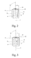
- the tubular cavity portion 4 may also be formed in the way shown in Fig. 2 where a portion of the top surface 10 is a cone mantle that has a juncture with the exhaust tube 12 at the vertex of the cone being at the lamp axis t.
- the top surface 10 has a rounded juncture with the mantle surface 11.
- the angle a made by the theoretical tangential planes s with the axis t does not exceed 120 degrees.
- a further embodiment of the cavity portion 4 suitable for the discharge lamp 1 is seen.
- the top surface 10 of the cavity portion 4 is convex when viewed from the inside of the discharge vessel 2 and is formed as a spherical surface where the center of the sphere is placed on the lamp axis t and its radius R is at least twice the tube radius r.
- the theoretical planes s placed on the top surface 10 make - adjacent to the mantle surface 11, at least over a distance of one-third the tube radius r from the mantle surface 11 - an angle exceeding 90 degrees with the lamp axis t.
Landscapes
- Physics & Mathematics (AREA)
- Electromagnetism (AREA)
- Engineering & Computer Science (AREA)
- Plasma & Fusion (AREA)
- Discharge Lamps And Accessories Thereof (AREA)
- Vessels And Coating Films For Discharge Lamps (AREA)
- Non-Portable Lighting Devices Or Systems Thereof (AREA)
Applications Claiming Priority (2)
| Application Number | Priority Date | Filing Date | Title |
|---|---|---|---|
| HU9400450 | 1994-02-17 | ||
| HU9400450A HU214131B (en) | 1994-02-17 | 1994-02-17 | Low-pressure discharge lamp without electrode |
Publications (2)
| Publication Number | Publication Date |
|---|---|
| EP0668605A2 true EP0668605A2 (fr) | 1995-08-23 |
| EP0668605A3 EP0668605A3 (fr) | 1997-03-26 |
Family
ID=10984834
Family Applications (1)
| Application Number | Title | Priority Date | Filing Date |
|---|---|---|---|
| EP95100561A Ceased EP0668605A3 (fr) | 1994-02-17 | 1995-01-17 | Lampe à décharge à basse pression sans électrodes. |
Country Status (4)
| Country | Link |
|---|---|
| EP (1) | EP0668605A3 (fr) |
| JP (1) | JPH07312207A (fr) |
| CA (1) | CA2142679A1 (fr) |
| HU (1) | HU214131B (fr) |
Family Cites Families (6)
| Publication number | Priority date | Publication date | Assignee | Title |
|---|---|---|---|---|
| US4048541A (en) * | 1976-06-14 | 1977-09-13 | Solitron Devices, Inc. | Crystal controlled oscillator circuit for illuminating electrodeless fluorescent lamp |
| JPS5628460A (en) * | 1979-08-15 | 1981-03-20 | Mitsubishi Electric Corp | High frequency starting device |
| NL8500738A (nl) * | 1985-03-14 | 1986-10-01 | Philips Nv | Elektrodeloze lagedrukontladingslamp. |
| NL8601702A (nl) * | 1986-06-30 | 1988-01-18 | Philips Nv | Elektrodeloze lagedrukontladingslamp. |
| US5291091A (en) * | 1991-01-25 | 1994-03-01 | U.S. Philips Corporation | Electrodeless low-pressure discharge |
| US5355054A (en) * | 1992-01-07 | 1994-10-11 | U.S. Philips Corporation | Electrodeless low-pressure discharge lamp having a cooling body with a partitioned vapor channel |
-
1994
- 1994-02-17 HU HU9400450A patent/HU214131B/hu not_active IP Right Cessation
-
1995
- 1995-01-17 EP EP95100561A patent/EP0668605A3/fr not_active Ceased
- 1995-02-16 CA CA 2142679 patent/CA2142679A1/fr not_active Abandoned
- 1995-02-17 JP JP5367595A patent/JPH07312207A/ja active Pending
Also Published As
| Publication number | Publication date |
|---|---|
| HUT70230A (en) | 1995-09-28 |
| HU9400450D0 (en) | 1994-05-30 |
| EP0668605A3 (fr) | 1997-03-26 |
| HU214131B (en) | 1997-12-29 |
| CA2142679A1 (fr) | 1995-08-18 |
| JPH07312207A (ja) | 1995-11-28 |
Similar Documents
| Publication | Publication Date | Title |
|---|---|---|
| US6064155A (en) | Compact fluorescent lamp as a retrofit for an incandescent lamp | |
| US4727294A (en) | Electrodeless low-pressure discharge lamp | |
| EP0294004B1 (fr) | Lampe de décharge à basse pression sans électrodes | |
| US4645967A (en) | Electrodeless low-pressure gas discharge lamp | |
| US5959405A (en) | Electrodeless fluorescent lamp | |
| US4959584A (en) | Luminaire for an electrodeless high intensity discharge lamp | |
| CN1118516A (zh) | 一种具有改进的荧光粉配置的无电极荧光灯及其制造方法 | |
| CA1273394A (fr) | Lampe electrique a globe en matiere synthetique | |
| EP0668605A2 (fr) | Lampe à décharge à basse pression sans électrodes | |
| US5416383A (en) | High-pressure discharge lamp and low-noise lamp operating system | |
| GB2092831A (en) | Ballasts for Gas Discharge Lamps, and a Lighting Unit with a Ballast and at Least One High Pressure Gas Discharge Lamp | |
| JP3478369B2 (ja) | 環形蛍光ランプおよび照明器具 | |
| US5296780A (en) | Arc discharge lamp having cementless right-angle base members | |
| US6548965B1 (en) | Electrodeless fluorescent lamp with low wall loading | |
| EP0675522A2 (fr) | Lampe à décharge à culotage d'un seul côté | |
| US7859176B2 (en) | High-pressure discharge lamp assembly | |
| US5760547A (en) | Multiple-discharge electrodeless fluorescent lamp | |
| JP2002015701A (ja) | 蛍光ランプおよび照明装置 | |
| EP0702846B1 (fr) | Couche de phosphore pour lampe a decharge sans electrode | |
| JP4304605B2 (ja) | 電球形蛍光ランプおよび照明装置 | |
| MXPA02004066A (es) | Unidad de lampara fluorescente circular y aparato de iluminacion. | |
| US7030564B2 (en) | Low-pressure discharge lamp | |
| GB1583460A (en) | Fluorescent lamp | |
| JP2001035441A (ja) | 電球形蛍光ランプ | |
| JP2006196347A (ja) | 蛍光ランプおよび照明器具 |
Legal Events
| Date | Code | Title | Description |
|---|---|---|---|
| PUAI | Public reference made under article 153(3) epc to a published international application that has entered the european phase |
Free format text: ORIGINAL CODE: 0009012 |
|
| AK | Designated contracting states |
Kind code of ref document: A2 Designated state(s): DE FR GB IT |
|
| PUAL | Search report despatched |
Free format text: ORIGINAL CODE: 0009013 |
|
| AK | Designated contracting states |
Kind code of ref document: A3 Designated state(s): DE FR GB IT |
|
| 17P | Request for examination filed |
Effective date: 19970925 |
|
| 17Q | First examination report despatched |
Effective date: 19980902 |
|
| GRAG | Despatch of communication of intention to grant |
Free format text: ORIGINAL CODE: EPIDOS AGRA |
|
| STAA | Information on the status of an ep patent application or granted ep patent |
Free format text: STATUS: THE APPLICATION HAS BEEN REFUSED |
|
| 18R | Application refused |
Effective date: 20020314 |