EP0669122A1 - Lit polyvalent pour malades - Google Patents
Lit polyvalent pour malades Download PDFInfo
- Publication number
- EP0669122A1 EP0669122A1 EP95100912A EP95100912A EP0669122A1 EP 0669122 A1 EP0669122 A1 EP 0669122A1 EP 95100912 A EP95100912 A EP 95100912A EP 95100912 A EP95100912 A EP 95100912A EP 0669122 A1 EP0669122 A1 EP 0669122A1
- Authority
- EP
- European Patent Office
- Prior art keywords
- section
- boards
- movable
- sickbed
- main shaft
- Prior art date
- Legal status (The legal status is an assumption and is not a legal conclusion. Google has not performed a legal analysis and makes no representation as to the accuracy of the status listed.)
- Granted
Links
Images





Classifications
-
- A—HUMAN NECESSITIES
- A61—MEDICAL OR VETERINARY SCIENCE; HYGIENE
- A61G—TRANSPORT, PERSONAL CONVEYANCES OR ACCOMMODATION SPECIALLY ADAPTED FOR PATIENTS OR DISABLED PERSONS; OPERATING TABLES OR CHAIRS; CHAIRS FOR DENTISTRY; FUNERAL DEVICES
- A61G7/00—Beds specially adapted for nursing; Devices for lifting patients or disabled persons
- A61G7/002—Beds specially adapted for nursing; Devices for lifting patients or disabled persons having adjustable mattress frame
- A61G7/015—Beds specially adapted for nursing; Devices for lifting patients or disabled persons having adjustable mattress frame divided into different adjustable sections, e.g. for Gatch position
Definitions
- the sickbed is usually so designed that a head portion and/or a rear portion thereof can be adjusted to incline at different angles.
- the inclination of the sickbed at its head portion and/or rear portion is not necessarily suitable for or meeting the requirement of all patients.
- two tenders are required to help the patient to the toilet room. It is therefore desirable to develop a multipurpose sickbed of which the head, middle, and rear portions as well as the left and right sides can be raised or lowered, inclined or leveled, or alternately raised for air ventilation purpose through different control mechanisms.
- a primary object of the present invention is to provide a multipurpose sickbed, and more particularly to provide a sickbed of which the bed boards can be partially raised, lowered, inclined, and leveled through a number of control means.
- the sickbed according to the present invention is equipped with a first control mechanism which controls the axial inclination of a head section of the bed, a second control mechanism which controls the alternate raising of movable boards of the head and a middle sections of the bed, a third control mechanism which controls the axial inclination of a rear section of the bed so that a raised bed rear board forms a footrest, a fourth control mechanism which controls the leftward or rightward inclination of a left or a right side of the head, middle, rear sections of the sickbed so that the patient on the bed may lie on side, and a fifth control mechanism which controls the descent of the middle section of the bed for the positioning of a bedpan or a urinal thereat to facilitate the convenient and comfortable excretion of the patient.
- the multipurpose sickbed according to the present invention is characterized in that:
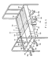
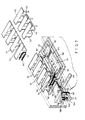
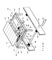
- a sickbed according to the present invention is divided into three sections, namely, a head section 100, a middle section 200, and a rear section 300. All of these three sections have the same bed board structure which includes a top layer, a middle layer, and a bottom layer.
- each section 100, 200, 300 includes a left half 110, 210, 310 and a right half 120, 220, 320.
- the left half 110, 210 consists of a plurality of alternately disposed fixed boards 111, 211 and movable boards 112, 212, and the right half 120, 220 also consists of a plurality of alternately disposed fixed boards 121, 221 and movable boards 122, 222.
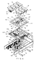
- the bottom layer of the head section 100 consists of a frame plate 140 having two laterally opposite rectangular openings 141, 141', a rotary shaft 142 fixed to a top middle portion thereof between the two openings 141, 141' and connecting a fourth and a fifth rotary wheels 144, 144' thereon, and two threaded rods 160, 160' rotatably connected near two side edges of the frame plate 140 by means of two pairs of fixing mounts 161, 161'.
- the middle layer of the head section 100 consists of two movable frame plates 150, 150' having an opening 151, 151' therein and laterally disposed on the frame plate 140 within the two rectangular openings 141, 141' and secured to the latter by means of hinges 159, 159' and screws 1591, 1592, as shown in Figs. 8 and 8-1, such that the movable frame plates 150, 150' can be pivotly turned about the hinges 159, 159'.
- Pads 149, 149' are provided on a top surface of the frame plate 140 at proper positions to facilitate the smooth movement of the movable frame plates 150, 150'.
- the movable frame plates 150, 150' are lowered to a lowest position in the frame plate 140, the movable boards 112, 122 and the fixed boards 111, 121 are also retained within the openings 151, 151' of the movable frame plates 150, 150' with their bottom surfaces in the plane of the frame plate 140.
- the movable frame plates 150, 150' are formed with a plurality of fixing holes 1111, 1211 on an outer side edge thereof, and connected on an upper inner side edge thereof two torsional leaf springs 152, 153, 152', 153' by means of screws 154, 154' or by means of welding.
- Each pair of the torsional leaf springs 152, 152', 153, 153' are connected to each other by means of a pin 157, 157' passing through pin holes 158, 158' formed at another end of the torsional leaf springs 152, 152', 153, 153'.
- half-crescent members 155, 155', 155", 155''', 156, 156', 156", 156'" are provided between the two movable frame plates 150, 150' at a lower inner edge thereof.
- the sickbed of the present invention is equipped with five control mechanisms, namely, the first, the second, the third, the fourth, and the fifth control mechanisms 130, 510, 330, 600, 230.
- the first control mechanism 130 is used to control the head section 100 and consists of a crank handle 130 near the rear end of the sickbed, a main shaft 131 integrally extending from the crank handle 130 and having a threaded section 132 formed at a predetermined position thereon, an internally threaded block 133 engaged with the threaded section 132 and having two stoppers 1331, 1332 formed at two sides thereof, and a trapezoidal member 134 having two spaced and downward tapered legs and an axially extended middle groove 1341 formed between the two legs so that the trapezoidal member 134 is received between the two stoppers 1331, 1332 with the threaded section 132 passing through the middle groove 1341.
- the internally threaded block 133 is prevented from turning along with the threaded section 132 but moves forward or backward thereon in a linear movement and thereby drives the trapezoidal member 134 to move upward or downward, respectively.
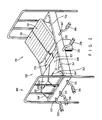
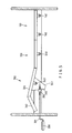
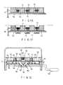
- the two legs of the trapezoidal member 134 have two outward projected flanges 1342, 1342' by which the trapezoidal member 134 is stopped at a certain height without disengaging from the internally threaded block 133 when it is moved upward by the same. Since an upper end of the trapezoidal member 134 is fixed to the frame plate 140, when the trapezoidal member 134 is moved upward through the first control mechanism 130, the head section 100 of the sickbed is lifted to form an inclination as shown in Figs. 2 and 3.
- the rear section 300 of the present invention can be inclined through the third control mechanism 330 in the same manner as that adopted by the first control mechanism 130 to incline the head section 100.
- the third control mechanism 330 consists of a crank handle 330, a main shaft 331, a threaded section 332, an internally threaded block 333, and a trapezoidal member 341, respectively having the same structure as that of the crank handle 130, main shaft 131, threaded section 132, block 133, and member 134.
- the left and the right halves 310, 320 of the rear section 300 each consists of a fixed board 311, 321 and a foot-support board 360, 360' which is pivotally connected to the fixed board 311, 321 by means of a hinge 361, 362, such that when the rear section 300 is lifted by the trapezoidal member 341, it is bent about the hinges 361, 362 and the fixed boards 311, 321 are inclined forward and the foot-support boards 360, 360' are inclined rearward, as shown in Figs. 2 and 5, for the patient's feet to put thereon.
- the elevation mechanism 500 is actuated by the second control mechanism 510 and mainly consists of a crank handle 510; a main shaft 511 one end of which is integrally connected to the crank handle 510 and the other end connects a first rotary wheel 512; a second rotary wheel 521 being driven to rotate by the first rotary wheel 512 through a chain 513 connecting them; a universal joint 522 which together with the second rotary wheel 521 form a transmission component 520 which is secured onto a fixed supporting member 410 by means of a fixing mount 523 such that the second rotary wheel 521 and the universal joint 522 turn synchronously; an expansion rod 524 connected to an upper portion of the universal joint 522 and having a base 5241 inside which a long groove 5243 is formed to fixedly receive an extended rod 5242 therein by means of a pin 5244 threading through a pin hole 52
- the universal joint 522 turns simultaneously, causing the expansion rod 524 connected to the universal joint 522 and the rotary shaft 142 to turn synchronously.
- the turning of the rotary shaft 142 causes the fourth and the fifth rotary wheels 144, 144' to synchronously turn, too.
- a seventh and an eighth rotary wheels 147, 147' respectively connected with the fourth and the fifth rotary wheels 144, 144' through chains 145, 145' and separately fixed to the left and the right half 110, 120 of the head section 100 are driven to rotate, too.
- the fixed boards 111, 121 are parallelly spaced and connected one another by an axle with a gear 113, 123 provided on the axle at each space between every two of the fixed boards.
- the movable boards 112, 122 are parallelly spaced and each is disposed in a space between the fixed boards 111, 121 and each of them is provided with a rack 114, 124 which engages with one of the gears 113, 123.
- the turning of the seventh and the eighth rotary wheels 147, 147' causes the axles and accordingly the gears 113, 123 to rotate and the latter further bring the racks 114, 124 to move upward or downward.
- the movable boards 112, 122 they are provided with guide bars 115, 115', 125, 125' which linearly slide up or down in the holes 1111, 1211 formed on the movable frame plates 150, 150'. The descent of the movable boards 112, 122 to separate from the fixed boards 111, 121 permits better air ventilation of the sickbed.
- the elevation mechanism 500 further includes a third rotary wheel 526, a sixth rotary wheel 525 connected to the third rotary wheel 526 via a link 5261, and a ninth rotary wheel 527 being coaxial with the sixth rotary wheel 525.
- the ninth rotary wheel 527 is further connected to a tenth rotary wheel 243 via a link (not shown) and drives the latter to rotate by a chain 528.
- the tenth rotary wheel 243 locates at a top middle portion of the middle section 200 between the two second movable frame plates 250, 250'.
- the ninth rotary wheel 527 may cooperates with the sixth rotary wheel 525 to adjust their position with the lowering or elevation of the tenth rotary wheel 243, and since the sixth rotary wheel 525 connects with the third rotary wheel 526 via the link 5261, the moved middle section 200 can still be driven by the third rotary wheel 526.
- the middle section 200 has substantially the same structure as that of the head section 100, that is, consists of a top layer including the left and the right halves 210, 220 each consists of fixed boards 211, 221 and movable boards 212, 222; a middle layer including movable frame plates 250, 250' provided with pads 249, 249'; and a bottom layer including a frame plate 240 having rectangular openings 241, 241'.
- a rotary shaft 248 is fixed onto the frame plate 240 between the two movable frame plates 250, 250' at a predetermined position by means of fixing mounts 242, 242'.
- the above- mentioned tenth rotary wheel 243 and an eleventh and a twelfth rotary wheels 244, 245 are fixed to the rotary shaft 248.
- the tenth rotary wheel 243 is driven to rotate by the ninth rotary wheel 527 via a chain 528, such that the eleventh and the twelfth rotary wheels 244, 245 are rotated to further drive thirteenth rotary wheels 246 fixed to one end of the fixed boards 211, 221.
- a threaded rod 260 is provided below the frame plate 240 of the middle section 200 and is fixed thereto by means of fixing mounts 261.
- the threaded rod 26 is used to control the inclination of the left and/or the right half 210, 220 and the structure thereof will be described in details as below.
- the fifth control mechanism 230 of the present invention consists of a main shaft 231 extending between and fixed onto two lateral sides of the frame plate 240. On each end of the main shaft 231 inside the frame plate 240, a driving gear 234, 234' are provided to drive a driven gear 235, 235' through a chain wheel 232 and a chain 233 such that driven gears 235, 235' rotates with the driving gears 234, 234' synchronously.
- the frame plate 240 has two pairs of racks 247, 247' formed at four bottom corners thereof engaging with the gears 234, 234', 235, 235', such that when the fifth control mechanism 230 is rotated, the gears 234, 234', 235, 235' fixed thereto drive the racks 247, 247' to move upward or downward and thereby, the middle section 200 is elevated or lowered.
- a recess so formed between the head and the rear sections 100, 300 can be used to accommodate a bedpan or a urinal to facilitate the excretion of the patient without leaving the sickbed.
- the tender can also save a lot of efforts.
- the fourth control mechanism 600 has a main shaft 601 on which a fourteenth, a fifteenth, a sixteenth, and a seventeenth rotary wheels 610, 620, 630, 640 are provided.
- the fourteenth and the fifteenth rotary wheels 610, 620 are used to drive the threaded rods 160, 160'
- the sixteenth rotary wheel 630 is used to drive the inclination of the middle section 200
- the seventeenth rotary wheel 640 is used to drive the inclination of the rear section 300. Since the manner of transmission of these rotary wheels are similar to those of other rotary wheels mentioned in previous paragraphs, it is not repeated herein.
- the fifteenth rotary wheel 620 connects an eighteenth rotary wheel 622 by means of a link 6221 and drives the latter to rotate via a chain 621.
- the eighteenth rotary wheel 622 is coaxial with a nineteenth rotary wheel 623 which is connected to a twentieth rotary wheel 624 via a link (not shown) and drives the latter to rotate through a chain (not shown). Due to the link connecting the nineteenth and the twentieth rotary wheels 623, 624, the distance between the two rotary wheels can be adequately adjusted when the movable frame plate 150 displaces.
- the fifteenth rotary wheel 620 drives the eighteenth, and accordingly, the nineteenth, and the twentieth rotary wheels 622, 623, 624 to rotate
- a twenty-first rotary wheel 625 fixed onto the threaded rod 160 is driven to rotate the threaded rod 160.
- the twentieth rotary wheel 624 has a rotary shaft 6243 which is fixed to the frame plate 140 by means of a fixing bracket 6244 and drives the twenty-first rotary wheel 625 through a chain 627, the twentieth rotary wheel 624 shall rotate when the frame plate 140 is displaced.
- the turning of the twentieth and the twenty-first rotary wheels 624, 625 further causes the fourteenth rotary wheel 610 on the threaded rod 160 to drive via a chain 611 a twenty- second rotary wheel 612 on the threaded rod 160' to rotate and thereby the threaded rod 160' rotates with the threaded rod 160 synchronously.
- the fourteenth, the sixteenth, and the seventeenth rotary wheels 610, 630, 640 all have the same transmission structure to effect displacement and position adjustment of the frame plate 140 and are therefore, not repeatedly described herein.
- the threaded rod 160 is provided near its middle point a control member 162 and at each end a twenty-first rotary wheel 625.
- the threaded rod 160 is turned in the same direction with the control member 162 moving leftward or rightward at the same time.
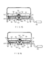
- the control member 162 has two support rod 1621, 1622 on its top and separately bearing against an inner side of the half-crescent members 155, 155', 156, 156' such that, when the control member 162 moves rightward, the movable frame plate 150 is pivotally raised at its outer edge to form an inclination while the other movable frame plate 150' is supported on the plane of the frame plate 140 without being lowered down.
- the fixed and the movable boards 121, 122 mounted on the movable frame plate 150 are thereby inclined, too. That is, only one lateral half of the sickbed is inwardly inclined so that the patient may be turned to lie on his/her right side.
- the fourth control mechanism 600 when the fourth control mechanism 600 is rotated in a reverse direction so that the control member 162 on the threaded rod 160 moves leftward, the inclined right half of the sickbed shall be lowered down to recover its level position. And, when the control member 162 keeps moving leftward, the left half 110 of the sickbed shall be pivotally raised at its outer edge to form an inward inclination so that the patient may be turned to lie on his/her left side.
- the 14th and the 15th rotary wheels 610, 620 are used to control the pivotal raising and inclination of the two halves of the head section 100
- the 16th rotary wheel 630 is used to control the pivotal raising and inclination of the two halves of the middle section 200
- the 17th rotary wheel 640 is used to control the pivotal raising and inclination of the two halves of the rear section 300.
- the fourth control mechanism 600 may control the whole bed surface of the sickbed, causing the left halves 110, 210, 310 or the right halves 120, 220, 320 thereof to pivotally raised at an outer edge to form an inward inclination at the same time to help the patient to lie on left or on right side.
- the rear section 300 has substantially the same structure as that of the head section 100, except that there is only one fixed board 311, 321 forming the left and the right halves 310, 320 of the rear section 300.
- movable boards can also be provided for the rear section 300, depending on actual need.
- the fixed boards 311, 321 are supported on movable frame plates 350, 350' which are hinged at inner edge to a frame plate 340.
- the structure of this portion is the same as that of the head and the middle sections 100, 200 and is not repeated herein.
Landscapes
- Health & Medical Sciences (AREA)
- Nursing (AREA)
- Life Sciences & Earth Sciences (AREA)
- Animal Behavior & Ethology (AREA)
- General Health & Medical Sciences (AREA)
- Public Health (AREA)
- Veterinary Medicine (AREA)
- Invalid Beds And Related Equipment (AREA)
- Percussion Or Vibration Massage (AREA)
- Orthopedics, Nursing, And Contraception (AREA)
Applications Claiming Priority (2)
| Application Number | Priority Date | Filing Date | Title |
|---|---|---|---|
| DE9403193U | 1994-02-25 | ||
| DE9403193U DE9403193U1 (de) | 1994-02-25 | 1994-02-25 | Krankenbett |
Publications (2)
| Publication Number | Publication Date |
|---|---|
| EP0669122A1 true EP0669122A1 (fr) | 1995-08-30 |
| EP0669122B1 EP0669122B1 (fr) | 1999-09-15 |
Family
ID=6905147
Family Applications (1)
| Application Number | Title | Priority Date | Filing Date |
|---|---|---|---|
| EP95100912A Expired - Lifetime EP0669122B1 (fr) | 1994-02-25 | 1995-01-24 | Lit polyvalent pour malades |
Country Status (3)
| Country | Link |
|---|---|
| EP (1) | EP0669122B1 (fr) |
| AT (1) | ATE184478T1 (fr) |
| DE (1) | DE9403193U1 (fr) |
Cited By (7)
| Publication number | Priority date | Publication date | Assignee | Title |
|---|---|---|---|---|
| CN101669859B (zh) * | 2008-09-11 | 2012-08-22 | 吴谨有 | 多功能病床 |
| CN109259972A (zh) * | 2018-09-07 | 2019-01-25 | 季松石 | 一种手术对接车的病人机械输送附加装置 |
| CN109498307A (zh) * | 2018-12-27 | 2019-03-22 | 滇西科技师范学院 | 一种心理学治疗催眠床 |
| CN112168533A (zh) * | 2020-11-06 | 2021-01-05 | 重庆大学附属肿瘤医院 | 一种医用多功能使用床 |
| CN113398531A (zh) * | 2021-06-28 | 2021-09-17 | 河南省中医院(河南中医药大学第二附属医院) | 一种医用重症病人下肢复健锻炼装置 |
| CN114533429A (zh) * | 2022-03-09 | 2022-05-27 | 倪斌 | 一种肾移植术后康复装置及其使用方法 |
| CN114795741A (zh) * | 2022-04-20 | 2022-07-29 | 江阴市中医院 | 一种脑卒中危重患者专用气垫床 |
Families Citing this family (1)
| Publication number | Priority date | Publication date | Assignee | Title |
|---|---|---|---|---|
| CN111643291B (zh) * | 2020-07-09 | 2024-07-12 | 威海威高齐全医疗设备有限公司 | 一种具有称重功能的三立柱病床及其支撑结构 |
Citations (4)
| Publication number | Priority date | Publication date | Assignee | Title |
|---|---|---|---|---|
| US2271201A (en) * | 1938-05-23 | 1942-01-27 | Mehr Otto | Hospital bed |
| GB2015872A (en) * | 1977-10-18 | 1979-09-19 | Girgis W H | Anti-Sore Bed |
| US5125122A (en) * | 1990-12-26 | 1992-06-30 | Chen Mau Shen | Tiltable bed mechanism |
| US5303437A (en) * | 1992-11-16 | 1994-04-19 | Hung Yung Feng | Multi-function and automatic sick bed |
-
1994
- 1994-02-25 DE DE9403193U patent/DE9403193U1/de not_active Expired - Lifetime
-
1995
- 1995-01-24 EP EP95100912A patent/EP0669122B1/fr not_active Expired - Lifetime
- 1995-01-24 AT AT95100912T patent/ATE184478T1/de active
Patent Citations (4)
| Publication number | Priority date | Publication date | Assignee | Title |
|---|---|---|---|---|
| US2271201A (en) * | 1938-05-23 | 1942-01-27 | Mehr Otto | Hospital bed |
| GB2015872A (en) * | 1977-10-18 | 1979-09-19 | Girgis W H | Anti-Sore Bed |
| US5125122A (en) * | 1990-12-26 | 1992-06-30 | Chen Mau Shen | Tiltable bed mechanism |
| US5303437A (en) * | 1992-11-16 | 1994-04-19 | Hung Yung Feng | Multi-function and automatic sick bed |
Cited By (10)
| Publication number | Priority date | Publication date | Assignee | Title |
|---|---|---|---|---|
| CN101669859B (zh) * | 2008-09-11 | 2012-08-22 | 吴谨有 | 多功能病床 |
| CN109259972A (zh) * | 2018-09-07 | 2019-01-25 | 季松石 | 一种手术对接车的病人机械输送附加装置 |
| CN109259972B (zh) * | 2018-09-07 | 2024-10-18 | 季松石 | 一种手术对接车的病人机械输送附加装置 |
| CN109498307A (zh) * | 2018-12-27 | 2019-03-22 | 滇西科技师范学院 | 一种心理学治疗催眠床 |
| CN112168533A (zh) * | 2020-11-06 | 2021-01-05 | 重庆大学附属肿瘤医院 | 一种医用多功能使用床 |
| CN113398531A (zh) * | 2021-06-28 | 2021-09-17 | 河南省中医院(河南中医药大学第二附属医院) | 一种医用重症病人下肢复健锻炼装置 |
| CN114533429A (zh) * | 2022-03-09 | 2022-05-27 | 倪斌 | 一种肾移植术后康复装置及其使用方法 |
| CN114533429B (zh) * | 2022-03-09 | 2023-09-15 | 南京医科大学第二附属医院 | 一种肾移植术后康复装置 |
| CN114795741A (zh) * | 2022-04-20 | 2022-07-29 | 江阴市中医院 | 一种脑卒中危重患者专用气垫床 |
| CN114795741B (zh) * | 2022-04-20 | 2023-12-08 | 江阴市中医院 | 一种脑卒中危重患者专用气垫床 |
Also Published As
| Publication number | Publication date |
|---|---|
| DE9403193U1 (de) | 1994-04-28 |
| EP0669122B1 (fr) | 1999-09-15 |
| ATE184478T1 (de) | 1999-10-15 |
Similar Documents
| Publication | Publication Date | Title |
|---|---|---|
| US5392479A (en) | Multipurpose sickbed | |
| US5303437A (en) | Multi-function and automatic sick bed | |
| JP2987290B2 (ja) | ベッド装置 | |
| US6230344B1 (en) | Adjustable bed | |
| US4494259A (en) | Adjustable bed | |
| US3015113A (en) | Adjustable bed | |
| US4718355A (en) | Vertically adjustable patient support table | |
| KR101317480B1 (ko) | 병원용 다기능 전동침대 | |
| JPS61128969A (ja) | 多姿勢ベッド | |
| EP0669122B1 (fr) | Lit polyvalent pour malades | |
| US5125122A (en) | Tiltable bed mechanism | |
| JP2923412B2 (ja) | ベッド装置 | |
| EP0705091B1 (fr) | Lit pour traitement intensif | |
| CN114404168B (zh) | 一种自动移动病床及病人移动方法 | |
| JPH0244225B2 (fr) | ||
| CA2143989C (fr) | Lit polyvalent pour malades | |
| KR100619432B1 (ko) | 환자 이송 침대 | |
| CN219049270U (zh) | 按摩床设备 | |
| KR950008969Y1 (ko) | 다기능 자동 병상 | |
| JPH06181952A (ja) | 患者用ベッド移し替え装置 | |
| KR0118592Y1 (ko) | 다용도 병상 | |
| JP2560368Y2 (ja) | リクライニングベッド及び床板ユニット | |
| DE2640985B2 (de) | Vorrichtung zum Überführen eines Patienten aus einer liegenden in eine sitzende Stellung und umgekehrt | |
| TWI882701B (zh) | 仰躺式站立輔助裝置 | |
| CN221636426U (zh) | 一种下沉式翻身护理床 |
Legal Events
| Date | Code | Title | Description |
|---|---|---|---|
| PUAI | Public reference made under article 153(3) epc to a published international application that has entered the european phase |
Free format text: ORIGINAL CODE: 0009012 |
|
| AK | Designated contracting states |
Kind code of ref document: A1 Designated state(s): AT BE CH DK ES FR GR IE IT LI LU MC NL PT SE |
|
| 17P | Request for examination filed |
Effective date: 19960227 |
|
| GRAG | Despatch of communication of intention to grant |
Free format text: ORIGINAL CODE: EPIDOS AGRA |
|
| 17Q | First examination report despatched |
Effective date: 19981210 |
|
| GRAG | Despatch of communication of intention to grant |
Free format text: ORIGINAL CODE: EPIDOS AGRA |
|
| GRAH | Despatch of communication of intention to grant a patent |
Free format text: ORIGINAL CODE: EPIDOS IGRA |
|
| GRAH | Despatch of communication of intention to grant a patent |
Free format text: ORIGINAL CODE: EPIDOS IGRA |
|
| GRAA | (expected) grant |
Free format text: ORIGINAL CODE: 0009210 |
|
| AK | Designated contracting states |
Kind code of ref document: B1 Designated state(s): AT BE CH DK ES FR GR IE IT LI LU MC NL PT SE |
|
| PG25 | Lapsed in a contracting state [announced via postgrant information from national office to epo] |
Ref country code: SE Free format text: THE PATENT HAS BEEN ANNULLED BY A DECISION OF A NATIONAL AUTHORITY Effective date: 19990915 Ref country code: NL Free format text: LAPSE BECAUSE OF FAILURE TO SUBMIT A TRANSLATION OF THE DESCRIPTION OR TO PAY THE FEE WITHIN THE PRESCRIBED TIME-LIMIT Effective date: 19990915 Ref country code: IT Free format text: LAPSE BECAUSE OF FAILURE TO SUBMIT A TRANSLATION OF THE DESCRIPTION OR TO PAY THE FEE WITHIN THE PRE;WARNING: LAPSES OF ITALIAN PATENTS WITH EFFECTIVE DATE BEFORE 2007 MAY HAVE OCCURRED AT ANY TIME BEFORE 2007. THE CORRECT EFFECTIVE DATE MAY BE DIFFERENT FROM THE ONE RECORDED.SCRIBED TIME-LIMIT Effective date: 19990915 Ref country code: GR Free format text: LAPSE BECAUSE OF NON-PAYMENT OF DUE FEES Effective date: 19990915 Ref country code: ES Free format text: THE PATENT HAS BEEN ANNULLED BY A DECISION OF A NATIONAL AUTHORITY Effective date: 19990915 |
|
| REF | Corresponds to: |
Ref document number: 184478 Country of ref document: AT Date of ref document: 19991015 Kind code of ref document: T |
|
| REG | Reference to a national code |
Ref country code: CH Ref legal event code: EP |
|
| ET | Fr: translation filed | ||
| REG | Reference to a national code |
Ref country code: IE Ref legal event code: FG4D |
|
| PG25 | Lapsed in a contracting state [announced via postgrant information from national office to epo] |
Ref country code: PT Free format text: LAPSE BECAUSE OF FAILURE TO SUBMIT A TRANSLATION OF THE DESCRIPTION OR TO PAY THE FEE WITHIN THE PRESCRIBED TIME-LIMIT Effective date: 19991215 Ref country code: DK Free format text: LAPSE BECAUSE OF FAILURE TO SUBMIT A TRANSLATION OF THE DESCRIPTION OR TO PAY THE FEE WITHIN THE PRESCRIBED TIME-LIMIT Effective date: 19991215 |
|
| PGFP | Annual fee paid to national office [announced via postgrant information from national office to epo] |
Ref country code: FR Payment date: 20000118 Year of fee payment: 6 |
|
| PGFP | Annual fee paid to national office [announced via postgrant information from national office to epo] |
Ref country code: CH Payment date: 20000119 Year of fee payment: 6 |
|
| PGFP | Annual fee paid to national office [announced via postgrant information from national office to epo] |
Ref country code: AT Payment date: 20000120 Year of fee payment: 6 |
|
| PGFP | Annual fee paid to national office [announced via postgrant information from national office to epo] |
Ref country code: BE Payment date: 20000121 Year of fee payment: 6 |
|
| PG25 | Lapsed in a contracting state [announced via postgrant information from national office to epo] |
Ref country code: LU Free format text: LAPSE BECAUSE OF NON-PAYMENT OF DUE FEES Effective date: 20000124 |
|
| PG25 | Lapsed in a contracting state [announced via postgrant information from national office to epo] |
Ref country code: MC Free format text: THE PATENT HAS BEEN ANNULLED BY A DECISION OF A NATIONAL AUTHORITY Effective date: 20000131 |
|
| PGFP | Annual fee paid to national office [announced via postgrant information from national office to epo] |
Ref country code: IE Payment date: 20000131 Year of fee payment: 6 |
|
| NLV1 | Nl: lapsed or annulled due to failure to fulfill the requirements of art. 29p and 29m of the patents act | ||
| REG | Reference to a national code |
Ref country code: CH Ref legal event code: NV Representative=s name: REBMANN-KUPFER & CO. PATENTANWAELTE |
|
| PLBE | No opposition filed within time limit |
Free format text: ORIGINAL CODE: 0009261 |
|
| STAA | Information on the status of an ep patent application or granted ep patent |
Free format text: STATUS: NO OPPOSITION FILED WITHIN TIME LIMIT |
|
| 26N | No opposition filed | ||
| PG25 | Lapsed in a contracting state [announced via postgrant information from national office to epo] |
Ref country code: IE Free format text: LAPSE BECAUSE OF NON-PAYMENT OF DUE FEES Effective date: 20010124 Ref country code: AT Free format text: LAPSE BECAUSE OF NON-PAYMENT OF DUE FEES Effective date: 20010124 |
|
| PG25 | Lapsed in a contracting state [announced via postgrant information from national office to epo] |
Ref country code: LI Free format text: LAPSE BECAUSE OF NON-PAYMENT OF DUE FEES Effective date: 20010131 Ref country code: CH Free format text: LAPSE BECAUSE OF NON-PAYMENT OF DUE FEES Effective date: 20010131 Ref country code: BE Free format text: LAPSE BECAUSE OF NON-PAYMENT OF DUE FEES Effective date: 20010131 |
|
| BERE | Be: lapsed |
Owner name: LIAO WINNER Effective date: 20010131 |
|
| REG | Reference to a national code |
Ref country code: CH Ref legal event code: PL |
|
| PG25 | Lapsed in a contracting state [announced via postgrant information from national office to epo] |
Ref country code: FR Free format text: LAPSE BECAUSE OF NON-PAYMENT OF DUE FEES Effective date: 20010928 |
|
| REG | Reference to a national code |
Ref country code: FR Ref legal event code: ST |
|
| REG | Reference to a national code |
Ref country code: IE Ref legal event code: MM4A |