EP0669183A1 - Schweissverfahren für zwei Teile einer Schaufel - Google Patents
Schweissverfahren für zwei Teile einer Schaufel Download PDFInfo
- Publication number
- EP0669183A1 EP0669183A1 EP95400354A EP95400354A EP0669183A1 EP 0669183 A1 EP0669183 A1 EP 0669183A1 EP 95400354 A EP95400354 A EP 95400354A EP 95400354 A EP95400354 A EP 95400354A EP 0669183 A1 EP0669183 A1 EP 0669183A1
- Authority
- EP
- European Patent Office
- Prior art keywords
- welding
- parts
- flange
- welding method
- contact surfaces
- Prior art date
- Legal status (The legal status is an assumption and is not a legal conclusion. Google has not performed a legal analysis and makes no representation as to the accuracy of the status listed.)
- Granted
Links
Images


Classifications
-
- B—PERFORMING OPERATIONS; TRANSPORTING
- B23—MACHINE TOOLS; METAL-WORKING NOT OTHERWISE PROVIDED FOR
- B23K—SOLDERING OR UNSOLDERING; WELDING; CLADDING OR PLATING BY SOLDERING OR WELDING; CUTTING BY APPLYING HEAT LOCALLY, e.g. FLAME CUTTING; WORKING BY LASER BEAM
- B23K20/00—Non-electric welding by applying impact or other pressure, with or without the application of heat, e.g. cladding or plating
- B23K20/12—Non-electric welding by applying impact or other pressure, with or without the application of heat, e.g. cladding or plating the heat being generated by friction; Friction welding
- B23K20/129—Non-electric welding by applying impact or other pressure, with or without the application of heat, e.g. cladding or plating the heat being generated by friction; Friction welding specially adapted for particular articles or work
-
- B—PERFORMING OPERATIONS; TRANSPORTING
- B23—MACHINE TOOLS; METAL-WORKING NOT OTHERWISE PROVIDED FOR
- B23K—SOLDERING OR UNSOLDERING; WELDING; CLADDING OR PLATING BY SOLDERING OR WELDING; CUTTING BY APPLYING HEAT LOCALLY, e.g. FLAME CUTTING; WORKING BY LASER BEAM
- B23K20/00—Non-electric welding by applying impact or other pressure, with or without the application of heat, e.g. cladding or plating
- B23K20/12—Non-electric welding by applying impact or other pressure, with or without the application of heat, e.g. cladding or plating the heat being generated by friction; Friction welding
- B23K20/1205—Non-electric welding by applying impact or other pressure, with or without the application of heat, e.g. cladding or plating the heat being generated by friction; Friction welding using translation movement
-
- B—PERFORMING OPERATIONS; TRANSPORTING
- B23—MACHINE TOOLS; METAL-WORKING NOT OTHERWISE PROVIDED FOR
- B23K—SOLDERING OR UNSOLDERING; WELDING; CLADDING OR PLATING BY SOLDERING OR WELDING; CUTTING BY APPLYING HEAT LOCALLY, e.g. FLAME CUTTING; WORKING BY LASER BEAM
- B23K2101/00—Articles made by soldering, welding or cutting
- B23K2101/001—Turbines
Definitions
- the invention relates to a process for welding two blade parts and can in particular be applied to the construction of so-called monoblock bladed discs (DAM), the disc of which is produced by molding or forging and machining. said and the parts of the blades called sleeves which are connected thereto, and, separately, the complement of the blades.
- DAM monoblock bladed discs
- the quality of the welding is generally insufficient for the two wires of the blades, which are called the leading edge and the trailing edge, because on the one hand the heating of the latter is very significantly less than that of the central part of the 'dawn, the fact that the opposite parts are alternately vented, and on the other hand the lateral expulsion of material is very low due to the lower temperature and the local thickness scaled down ; finally, this venting involves a risk of contamination of the metal at these locations by oxidation.
- the criteria for acceptance for repair may prohibit reloading the cuff, which is alongside the finished product, with metal.
- the invention makes it possible to provide a correct or good weld of the blades, including at the leading and trailing edges, by using two blade parts generally in their final shape, that is to say without excess thickness, except at immediate vicinity of the welding area.
- it relates to a process for welding two blade parts, in which the blade parts are clamped between pairs of jaws and brought into contact with each other on their surfaces to be welded by a movement of approach pairs of jaws, these jaws allowing the parts to be welded not to deform under the welding pressure, and this method is characterized in that a flange is arranged on the contact surfaces of the blade parts, at least at the edges of attack and flight of said surfaces. The flange extends around the contact surfaces: either it is interposed between them, or it is flush with these surfaces and it then extends only around the blade parts.
- the flange is not an integral part of the blade but is attached to it, which completely distinguishes the invention from the already known solution.
- the only machining that is necessary after welding is a deburring-adjustment to detach the flange.
- the flange is a plate housed between the contact surfaces and which is destroyed during welding, because of the temperature rise brought for welding and the force exerted between the contact surfaces. It is possible that the wafer provides a little filler material for the weld, but this effect is not specially sought after and remains anyway secondary to the need to obtain a good weld.
- the flange is divided into two parts respectively arranged around the contact surfaces, flush with said surfaces, and retained by their edges by respective edges of the pairs of jaws. The material of the collar then does not participate at all in the welding of the blade, but its thermal role remains.
- Linear friction welding, flash welding or welding by forging and fusion in particular can be used, since the invention is implemented in the same way.
- a linear friction welding machine comprises, as seen in FIG. 1, two pairs of jaws 1 and 2, whose jaws, respectively 3, 4 and 5, 6 are shaped with bearing surfaces in the shape of parts which they enclose and united to supports 7 and 8 sketched by jacks 12 or similar devices to bring them together.
- the supports 7 and 8 can be moved reciprocally relative to each other and brought together to produce with sufficient pressure the friction movement responsible for heating and finally the weld.
- the pair of jaws 1 grips the end 9 of the blade to be welded, and the other pair of jaws 2 grips the cuff 10; the hub of the disc 11 is linked to the support 8 by means not shown.
- a flat plate 15 in the form of a flange is welded to the contact surface 16 of the blade tip 9.
- the contact surface 17 of the sleeve 10 is free.
- the flange 15 extends beyond the blade section in the thickness direction, as can be seen in the figure, and also extends beyond the width, so as to provide the material necessary for heating the edge d attack and the trailing edge and to limit the exposure of the surfaces to be welded.
- the plate 15 is heated and deformed during the welding and forging which follows it, and its material is rejected on both sides of the space between the pairs of jaws 1 and 2.
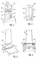
- Figures 2 to 5 including Figure 2 shows a cross section of the apparatus, Figure 3 a top view, Figure 4 a perspective view and Figure 5 a longitudinal section, show a design where the plate 15 integral of the end 9 is replaced by a plate 20 placed between the contact surfaces 16 and 17 and which it is then necessary to retain against the reciprocating movement of the pairs of jaws 1 and 2 by holding it between the flanges 21 and 22 of the two jaws 5 and 6 of the same pair.
- the flanges 21 and 22 also include bearing surfaces for correctly placing the wafer 20. These surfaces do not extend to the cuff 10, to avoid contact of the molten parts of the wafer 20.
- a wedge 18 is interposed between the plate 20 and the flange 21, of which the facing faces are bevelled to rest on the oblique faces of the corner 18.
- the tightening is ensured by a screw 38 engaged in a console 39 above the flange 21 and linked to it: the screw 38 weighs on the corner 18 , lowers it on the jaw 5, which retains the plate 20 against a reverse movement.
- a similar device exists for the other jaw 6 and the other flange 22.
- the embodiment of the welding is identical to that of FIG. 1. It can be seen in FIG. 3 that the plate 20 extends, in width, beyond the leading 23 and trailing 24 edges.
- FIGS. 6 and 7 represent the situation at the start and at the end of the welding.
- a flange 25 formed of two parts 26 and 27 is used, respectively associated with the end 9 and with the cuff 10 of the blade. More specifically, the parts 26 and 27 of the flange 25 are arranged around the portions of these parts which are adjacent to the contact surfaces 16 and 17, and they each consist of pieces, respectively 28, 29 and 30, 31, touching a respective side - lower or upper surface - of the blade and touching each other beyond the leading and trailing edges as seen in FIGS. 6, 7 and 8.
- the flange parts 26 and 27 are flush at the contact surfaces 16 and 17 are retained in edges 21, 22 and 33, 34 of the jaws 5, 6, 3 and 4 and are placed at the bottom of the imprints delimited by these edges.
- the flange 25 is therefore completely retained and becomes plastic during welding so that the crushed material flows back and forms a burr 35 emerging between the pairs of jaws 1 and 2 at the end of the welding, when the jaws have been stopped and removed. the forging pressure to obtain a blade of the desired length.
- the pieces of the flange 25 are then welded together and at dawn, when they were joined to the end 9 and to the cuff 10 before welding without being fixed to these parts, but a complete connection of the six elements occurred during welding and thermal conduction was then fully ensured.
- the pieces 28 to 31 may consist of portions of sheet metal machined to the local profiles of the blades. A simple machining operation suffices to remove the burr 35 and the remainder of the collar 25 as in the other embodiments.
- the flange pieces 28, 29 extend from the leading edge 23 to the trailing edge 24 and beyond these edges, where they abut, but, as shown in FIG. Figure 9, we could only have them in the vicinity of these edges where the thermal conduction must more precisely be ensured, and they would be divided into two fragments 28a and 28b, 29a and 29b disjoint.
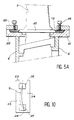
- the flanges 21, 22, 33 and 34 would then have an appropriate shape in order to avoid any movement during welding, as already shown in FIG. 5A for example.
- fragments 28a and 29a constituted only two joined parts of a single element 36 of flange disposed around the leading edge 23, as well as the fragments 28b and 29b for another element 37 of flange around the trailing edge 24, as shown in FIG. 10.
Landscapes
- Engineering & Computer Science (AREA)
- Mechanical Engineering (AREA)
- Pressure Welding/Diffusion-Bonding (AREA)
- Turbine Rotor Nozzle Sealing (AREA)
Applications Claiming Priority (2)
| Application Number | Priority Date | Filing Date | Title |
|---|---|---|---|
| FR9402026 | 1994-02-23 | ||
| FR9402026A FR2716397B1 (fr) | 1994-02-23 | 1994-02-23 | Procédé de soudage de deux parties d'aube. |
Publications (2)
| Publication Number | Publication Date |
|---|---|
| EP0669183A1 true EP0669183A1 (de) | 1995-08-30 |
| EP0669183B1 EP0669183B1 (de) | 1997-04-16 |
Family
ID=9460332
Family Applications (1)
| Application Number | Title | Priority Date | Filing Date |
|---|---|---|---|
| EP95400354A Expired - Lifetime EP0669183B1 (de) | 1994-02-23 | 1995-02-21 | Schweissverfahren für zwei Teile einer Schaufel |
Country Status (7)
| Country | Link |
|---|---|
| US (1) | US5551623A (de) |
| EP (1) | EP0669183B1 (de) |
| JP (1) | JP3072239B2 (de) |
| CA (1) | CA2142423C (de) |
| DE (1) | DE69500234T2 (de) |
| FR (1) | FR2716397B1 (de) |
| IL (1) | IL112758A (de) |
Cited By (11)
| Publication number | Priority date | Publication date | Assignee | Title |
|---|---|---|---|---|
| EP0850718A1 (de) * | 1996-12-24 | 1998-07-01 | United Technologies Corporation | Verfahrem zum Linearreibschweissen |
| EP0924016A1 (de) * | 1997-12-19 | 1999-06-23 | United Technologies Corporation | Linearreibschweissverfahren und hergestelltes Werkstück dafür |
| DE19807637A1 (de) * | 1998-02-23 | 1999-08-26 | Mtu Muenchen Gmbh | Reibschweißverfahren zur Beschaufelung eines Rotors für eine Strömungsmaschine |
| EP1213088A1 (de) * | 2000-12-07 | 2002-06-12 | Snecma Moteurs | Haltausrüstung einer Schaufel und Verwendung zum Reibschweissen von Schaufeln |
| FR2902360A1 (fr) * | 2006-06-19 | 2007-12-21 | Snecma Sa | Dispositif de maintien de pieces dans un procede de reparation d'une aube d'un disque aubage monobloc d'une turbomachine |
| CN102672302A (zh) * | 2011-12-24 | 2012-09-19 | 河南科技大学 | 带锯条的断口焊接及裂纹修复方法以及配套的烧焊工装 |
| US8479391B2 (en) | 2009-12-16 | 2013-07-09 | United Technologies Corporation | Consumable collar for linear friction welding of blade replacement for damaged integrally bladed rotors |
| CN103547402A (zh) * | 2011-04-25 | 2014-01-29 | 株式会社Ihi | 摩擦接合方法以及接合构造体 |
| WO2014083275A1 (fr) | 2012-11-28 | 2014-06-05 | Snecma | Procede de soudage par friction d'une pale sur un disque de rotor d'une turbomachine; disque aubage monobloc correspondant |
| EP2998060A1 (de) * | 2014-09-16 | 2016-03-23 | Rolls-Royce plc | Verfahren zum austauschen beschädigter schaufel |
| US9694440B2 (en) | 2010-10-22 | 2017-07-04 | United Technologies Corporation | Support collar geometry for linear friction welding |
Families Citing this family (26)
| Publication number | Priority date | Publication date | Assignee | Title |
|---|---|---|---|---|
| AU3971397A (en) * | 1996-08-16 | 1998-03-06 | Meritor Light Vehicle Ssytems, Inc. | Linear friction welded brake shoe assembly |
| DE19647707C2 (de) * | 1996-11-11 | 2003-08-21 | Untergrundspeicher Und Geotech | Verfahren und Vorrichtung zum Verbinden von Bauteilen |
| US5755031A (en) * | 1996-11-12 | 1998-05-26 | United Technologies Corporation | Method for attaching a rotor blade to an integrally bladed rotor |
| FR2760985B1 (fr) * | 1997-03-20 | 1999-04-30 | Snecma | Procede de soudage par friction d'une ebauche d'aube a un disque de rotor |
| US6007628A (en) * | 1997-12-19 | 1999-12-28 | United Technologies Corporation | Clamping fixture for a rotor blade shroud |
| US6244495B1 (en) * | 1998-11-06 | 2001-06-12 | United Technologies Corporation | Gripper |
| US6478545B2 (en) * | 2001-03-07 | 2002-11-12 | General Electric Company | Fluted blisk |
| US6910616B2 (en) * | 2002-03-07 | 2005-06-28 | The Boeing Company | Preforms for forming machined structural assemblies |
| FR2859933B1 (fr) * | 2003-09-19 | 2006-02-10 | Snecma Moteurs | Procede de fabrication ou de reparation d'un disque aubage monobloc |
| GB0327552D0 (en) * | 2003-11-27 | 2003-12-31 | Rolls Royce Plc | A method of fabricating or repairing an assembly |
| FR2870309B1 (fr) * | 2004-05-17 | 2006-07-07 | Snecma Moteurs Sa | Procede d'assemblage de disques aubages monoblocs et dispositif d'amortissement des vibrations des aubes de ces disques |
| GB0412775D0 (en) * | 2004-06-09 | 2004-07-07 | Rolls Royce Plc | Method of replacing damaged aerofoil |
| DE102004032461A1 (de) * | 2004-06-30 | 2006-02-02 | Rolls-Royce Deutschland Ltd & Co Kg | Verfahren und Reparatur-Schaufelteil zur BLISK-Reparatur oder zur Neuherstellung von BLISKs |
| EP1698423B1 (de) * | 2005-03-03 | 2008-03-26 | MTU Aero Engines GmbH | Verfahren zum Reibschweissfügen von einer Laufschaufel an einen Rotorgrundkörper mit Bewegung eines zwischen der Laufschaufel und dem Rotorgrundkörper angeordneten Fügeteils |
| DE102005045954A1 (de) * | 2005-09-26 | 2007-04-19 | Gkss-Forschungszentrum Geesthacht Gmbh | Verfahren und Vorrichtung zum Herstellen einer Schweißverbindung zwischen den Oberflächen zweier flächiger Werkstücke |
| JP4930265B2 (ja) * | 2007-08-08 | 2012-05-16 | 株式会社Ihi | 部品の接合方法及び翼部品の補修方法 |
| US20090185908A1 (en) * | 2008-01-21 | 2009-07-23 | Honeywell International, Inc. | Linear friction welded blisk and method of fabrication |
| US8267663B2 (en) * | 2008-04-28 | 2012-09-18 | Pratt & Whitney Canada Corp. | Multi-cast turbine airfoils and method for making same |
| DE102008051934A1 (de) | 2008-10-09 | 2010-04-15 | Mtu Aero Engines Gmbh | Verfahren zum Herstellen eines Rotors und Rotor |
| DE102009043184A1 (de) * | 2009-09-26 | 2011-04-07 | Mtu Aero Engines Gmbh | Verfahren zur Reparatur eines integralen Rotors und integraler Rotor |
| US9726044B2 (en) | 2013-02-12 | 2017-08-08 | United Technologies Corporation | Consumable assembly mistake proofing tool for a gas turbine engine |
| EP3613531B1 (de) * | 2015-11-09 | 2023-08-23 | IHI Corporation | Vorrichtung zum linearen reibschweissen |
| GB201519805D0 (en) * | 2015-11-10 | 2015-12-23 | Rolls Royce Plc | Rotary friction welding |
| GB2560001B (en) * | 2017-02-24 | 2019-07-17 | Rolls Royce Plc | A weld stub arrangement and a method of using the arrangement to make an article |
| US10525548B2 (en) | 2017-07-20 | 2020-01-07 | General Electric Company | Friction welding method |
| CN111408912B (zh) * | 2020-05-14 | 2021-08-20 | 中国兵器工业第五九研究所 | 一种小直径窄间隙薄壁多叶片构件的制备方法及夹持工装 |
Citations (5)
| Publication number | Priority date | Publication date | Assignee | Title |
|---|---|---|---|---|
| JPS57139485A (en) * | 1981-02-25 | 1982-08-28 | Hitachi Cable Ltd | Connecting method of metallic material |
| JPS58159988A (ja) * | 1982-03-19 | 1983-09-22 | Hitachi Ltd | 拡散接合インサ−ト材及び拡散接合方法 |
| EP0145897A1 (de) * | 1983-11-03 | 1985-06-26 | BBC Aktiengesellschaft Brown, Boveri & Cie. | Fügeverfahren |
| GB2237758A (en) * | 1989-11-07 | 1991-05-15 | Rolls Royce Plc | Rotor assembly and method of manufacture |
| EP0486755A2 (de) * | 1990-11-22 | 1992-05-27 | A & S Corporation | Reibungsschweissverfahren zum Verbinden einer Felge mit einer Scheibe eines Scheibenrades |
Family Cites Families (4)
| Publication number | Priority date | Publication date | Assignee | Title |
|---|---|---|---|---|
| BE789029A (fr) * | 1971-12-20 | 1973-01-15 | Gen Electric | Article metallique soude par frottement et procede de fabrication d'un tel article |
| US5188275A (en) * | 1990-05-24 | 1993-02-23 | Rolls-Royce Plc | Friction bonding clamp for a rotor blade |
| GB9309822D0 (en) * | 1993-05-13 | 1993-06-23 | Allwood Searle & Timney | Improvements relating to friction welding |
| GB9309819D0 (en) * | 1993-05-13 | 1993-06-23 | Allwood Searle & Timney | Imprivements relating to friction welding |
-
1994
- 1994-02-23 FR FR9402026A patent/FR2716397B1/fr not_active Expired - Fee Related
-
1995
- 1995-02-13 CA CA002142423A patent/CA2142423C/en not_active Expired - Fee Related
- 1995-02-17 US US08/390,317 patent/US5551623A/en not_active Expired - Lifetime
- 1995-02-21 EP EP95400354A patent/EP0669183B1/de not_active Expired - Lifetime
- 1995-02-21 DE DE69500234T patent/DE69500234T2/de not_active Expired - Lifetime
- 1995-02-23 IL IL11275895A patent/IL112758A/xx not_active IP Right Cessation
- 1995-02-23 JP JP7035311A patent/JP3072239B2/ja not_active Expired - Fee Related
Patent Citations (5)
| Publication number | Priority date | Publication date | Assignee | Title |
|---|---|---|---|---|
| JPS57139485A (en) * | 1981-02-25 | 1982-08-28 | Hitachi Cable Ltd | Connecting method of metallic material |
| JPS58159988A (ja) * | 1982-03-19 | 1983-09-22 | Hitachi Ltd | 拡散接合インサ−ト材及び拡散接合方法 |
| EP0145897A1 (de) * | 1983-11-03 | 1985-06-26 | BBC Aktiengesellschaft Brown, Boveri & Cie. | Fügeverfahren |
| GB2237758A (en) * | 1989-11-07 | 1991-05-15 | Rolls Royce Plc | Rotor assembly and method of manufacture |
| EP0486755A2 (de) * | 1990-11-22 | 1992-05-27 | A & S Corporation | Reibungsschweissverfahren zum Verbinden einer Felge mit einer Scheibe eines Scheibenrades |
Non-Patent Citations (2)
| Title |
|---|
| PATENT ABSTRACTS OF JAPAN vol. 6, no. 242 (M - 175) 30 November 1982 (1982-11-30) * |
| PATENT ABSTRACTS OF JAPAN vol. 7, no. 283 (M - 263) 16 December 1983 (1983-12-16) * |
Cited By (23)
| Publication number | Priority date | Publication date | Assignee | Title |
|---|---|---|---|---|
| EP0850718A1 (de) * | 1996-12-24 | 1998-07-01 | United Technologies Corporation | Verfahrem zum Linearreibschweissen |
| US5865364A (en) * | 1996-12-24 | 1999-02-02 | United Technologies Corporation | Process for linear friction welding |
| EP0924016A1 (de) * | 1997-12-19 | 1999-06-23 | United Technologies Corporation | Linearreibschweissverfahren und hergestelltes Werkstück dafür |
| US6106233A (en) * | 1997-12-19 | 2000-08-22 | United Technologies Corporation | Method for linear friction welding and product made by such method |
| US6219916B1 (en) | 1997-12-19 | 2001-04-24 | United Technologies Corporation | Method for linear friction welding and product made by such method |
| DE19807637A1 (de) * | 1998-02-23 | 1999-08-26 | Mtu Muenchen Gmbh | Reibschweißverfahren zur Beschaufelung eines Rotors für eine Strömungsmaschine |
| EP0937531A3 (de) * | 1998-02-23 | 2000-10-18 | Mtu Motoren- Und Turbinen-Union MàNchen Gmbh | Reibschweissverfahren zur Beschaufelung eines Rotors für eine Strömungsmaschine |
| DE19807637C2 (de) * | 1998-02-23 | 2001-01-11 | Mtu Muenchen Gmbh | Reibschweißverfahren zur Beschaufelung eines Rotors für eine Strömungsmaschine |
| US6595401B2 (en) | 2000-12-07 | 2003-07-22 | Snecma-Moteurs | Blade maintenance tool, and its application to friction welding of blades |
| EP1213088A1 (de) * | 2000-12-07 | 2002-06-12 | Snecma Moteurs | Haltausrüstung einer Schaufel und Verwendung zum Reibschweissen von Schaufeln |
| FR2817783A1 (fr) * | 2000-12-07 | 2002-06-14 | Snecma Moteurs | Outillage de maintien d'une aube, et son application au soudage par friction des aubes |
| US8383979B2 (en) | 2006-06-19 | 2013-02-26 | Snecma | Part-holding device in a repairing method for a blade of a monobloc bladed disc in a turbo-machine |
| FR2902360A1 (fr) * | 2006-06-19 | 2007-12-21 | Snecma Sa | Dispositif de maintien de pieces dans un procede de reparation d'une aube d'un disque aubage monobloc d'une turbomachine |
| EP1870192A1 (de) * | 2006-06-19 | 2007-12-26 | Snecma | Vorrichtung zum Spannen von Werkstücken bei einem Reparaturverfahren einer Schaufel einer integral beschaufelten Turbinenrotorscheibe |
| US8479391B2 (en) | 2009-12-16 | 2013-07-09 | United Technologies Corporation | Consumable collar for linear friction welding of blade replacement for damaged integrally bladed rotors |
| US9694440B2 (en) | 2010-10-22 | 2017-07-04 | United Technologies Corporation | Support collar geometry for linear friction welding |
| CN103547402A (zh) * | 2011-04-25 | 2014-01-29 | 株式会社Ihi | 摩擦接合方法以及接合构造体 |
| CN103547402B (zh) * | 2011-04-25 | 2016-03-09 | 株式会社Ihi | 摩擦接合方法以及接合构造体 |
| CN102672302A (zh) * | 2011-12-24 | 2012-09-19 | 河南科技大学 | 带锯条的断口焊接及裂纹修复方法以及配套的烧焊工装 |
| WO2014083275A1 (fr) | 2012-11-28 | 2014-06-05 | Snecma | Procede de soudage par friction d'une pale sur un disque de rotor d'une turbomachine; disque aubage monobloc correspondant |
| US9869189B2 (en) | 2012-11-28 | 2018-01-16 | Safran Aircraft Engines | Method for friction welding a blade onto a turbine engine rotor disc; corresponding integral blade disc |
| EP2998060A1 (de) * | 2014-09-16 | 2016-03-23 | Rolls-Royce plc | Verfahren zum austauschen beschädigter schaufel |
| US9500080B2 (en) | 2014-09-16 | 2016-11-22 | Rolls-Royce Plc | Method of replacing damaged aerofoil |
Also Published As
| Publication number | Publication date |
|---|---|
| EP0669183B1 (de) | 1997-04-16 |
| FR2716397B1 (fr) | 1996-04-05 |
| US5551623A (en) | 1996-09-03 |
| DE69500234T2 (de) | 1997-08-14 |
| CA2142423C (en) | 2005-09-13 |
| DE69500234D1 (de) | 1997-05-22 |
| JP3072239B2 (ja) | 2000-07-31 |
| FR2716397A1 (fr) | 1995-08-25 |
| IL112758A (en) | 1997-11-20 |
| JPH07284994A (ja) | 1995-10-31 |
| IL112758A0 (en) | 1995-05-26 |
| CA2142423A1 (en) | 1995-08-24 |
Similar Documents
| Publication | Publication Date | Title |
|---|---|---|
| EP0669183B1 (de) | Schweissverfahren für zwei Teile einer Schaufel | |
| EP0034549B1 (de) | Verfahren zum Einrollen von Rohren in Platten und Werkzeug zur Durchführung dieses Verfahrens | |
| EP0850718B1 (de) | Verfahrem zum Linearreibschweissen | |
| EP2342523B1 (de) | Rippe für einen wärmetauscher und wärmetauscher mit einer solchen rippe | |
| EP2994293B1 (de) | Einrichtung zum befestigen einer metallverstärkung an der austrittskante einer turbinenschaufel und verfahren zur verwendung solch einer einrichtung | |
| EP1213088B1 (de) | Haltausrüstung einer Schaufel und Verwendung zum Reibschweissen von Schaufeln | |
| FR2715216A1 (fr) | Tube d'échangeur de chaleur, procédé pour sa conformation et échangeur de chaleur comprenant de tels tubes. | |
| FR2744169A1 (fr) | Dispositif de fixation par rivetage des aubes mobiles sur la roue mobile, notamment d'une turbine d'un moteur a turbine a gaz | |
| FR2970192A1 (fr) | Outillage et procede de forgeage a chaud de toles | |
| EP2789888A1 (de) | Spannvorrichtung zum dichten Verbinden von glatten Rohren | |
| EP1481756A1 (de) | Verfahren zur Herstellung einer hohlen Turbinenschaufel | |
| FR2909574A1 (fr) | Mandrin de serrage. | |
| EP0949977B1 (de) | Verfahren zum quereinpressen eines zylindrischen teils in ein rohrförmiges teil und entsprechende einheit aus zwei teilen | |
| EP0516559B1 (de) | Verfahren zum Schweissen von Kupferteilen | |
| FR2656917A1 (fr) | Procede pour doubler une cheminee et manchon d'assemblage des sections de tube d'un tube interieur destine a cet effet. | |
| EP1540229B1 (de) | Klemmring | |
| EP0196971B1 (de) | Wiederherstellungsverfahren durch Verkleidung eines Dampfgeneratorrohres | |
| FR2728667A1 (fr) | Echangeur de chaleur, tube pour echangeur de chaleur et procedes pour leur fabrication | |
| EP0653255B1 (de) | Neuer nietartiger Verbindungspunkt für Bleche durch Kaltfliessen und Werkzeugmaschine zum Durchführen eines solchen Verbindungspunktes | |
| EP1164346B1 (de) | Dichtungshülse zum Erzielen einer dichten Verbindung zwischen zwei flachen paralellen Wänden aus dünnwandinem Blech | |
| FR2760985A1 (fr) | Procede de soudage par friction d'une ebauche d'aube a un disque de rotor | |
| EP0508850A1 (de) | Reduzierzange für Rohre und dergleichen | |
| FR2737543A1 (fr) | Cheville a expansion | |
| EP0803301B1 (de) | Verfahren zur Herstellung eines Gegenstandes durch superplastische Formung und Diffusionsschweissung | |
| FR2520475A1 (fr) | Disque de rupture se deformant sur la face envers et procede de fabrication |
Legal Events
| Date | Code | Title | Description |
|---|---|---|---|
| PUAI | Public reference made under article 153(3) epc to a published international application that has entered the european phase |
Free format text: ORIGINAL CODE: 0009012 |
|
| 17P | Request for examination filed |
Effective date: 19950311 |
|
| AK | Designated contracting states |
Kind code of ref document: A1 Designated state(s): BE DE FR GB IT SE |
|
| GRAG | Despatch of communication of intention to grant |
Free format text: ORIGINAL CODE: EPIDOS AGRA |
|
| GRAH | Despatch of communication of intention to grant a patent |
Free format text: ORIGINAL CODE: EPIDOS IGRA |
|
| 17Q | First examination report despatched |
Effective date: 19960925 |
|
| GRAH | Despatch of communication of intention to grant a patent |
Free format text: ORIGINAL CODE: EPIDOS IGRA |
|
| GRAA | (expected) grant |
Free format text: ORIGINAL CODE: 0009210 |
|
| AK | Designated contracting states |
Kind code of ref document: B1 Designated state(s): BE DE FR GB IT SE |
|
| ITF | It: translation for a ep patent filed | ||
| REF | Corresponds to: |
Ref document number: 69500234 Country of ref document: DE Date of ref document: 19970522 |
|
| GBT | Gb: translation of ep patent filed (gb section 77(6)(a)/1977) |
Effective date: 19970501 |
|
| PLBE | No opposition filed within time limit |
Free format text: ORIGINAL CODE: 0009261 |
|
| STAA | Information on the status of an ep patent application or granted ep patent |
Free format text: STATUS: NO OPPOSITION FILED WITHIN TIME LIMIT |
|
| 26N | No opposition filed | ||
| REG | Reference to a national code |
Ref country code: GB Ref legal event code: IF02 |
|
| REG | Reference to a national code |
Ref country code: FR Ref legal event code: TP Ref country code: FR Ref legal event code: CD |
|
| REG | Reference to a national code |
Ref country code: FR Ref legal event code: CD |
|
| REG | Reference to a national code |
Ref country code: GB Ref legal event code: 732E Free format text: REGISTERED BETWEEN 20120517 AND 20120523 |
|
| PGFP | Annual fee paid to national office [announced via postgrant information from national office to epo] |
Ref country code: IT Payment date: 20120126 Year of fee payment: 18 |
|
| PGFP | Annual fee paid to national office [announced via postgrant information from national office to epo] |
Ref country code: SE Payment date: 20130130 Year of fee payment: 19 Ref country code: DE Payment date: 20130124 Year of fee payment: 19 Ref country code: GB Payment date: 20130129 Year of fee payment: 19 |
|
| PGFP | Annual fee paid to national office [announced via postgrant information from national office to epo] |
Ref country code: BE Payment date: 20130128 Year of fee payment: 19 |
|
| PGFP | Annual fee paid to national office [announced via postgrant information from national office to epo] |
Ref country code: FR Payment date: 20140205 Year of fee payment: 20 |
|
| BERE | Be: lapsed |
Owner name: SNECMA Effective date: 20140228 |
|
| REG | Reference to a national code |
Ref country code: DE Ref legal event code: R119 Ref document number: 69500234 Country of ref document: DE |
|
| REG | Reference to a national code |
Ref country code: SE Ref legal event code: EUG |
|
| GBPC | Gb: european patent ceased through non-payment of renewal fee |
Effective date: 20140221 |
|
| PG25 | Lapsed in a contracting state [announced via postgrant information from national office to epo] |
Ref country code: SE Free format text: LAPSE BECAUSE OF NON-PAYMENT OF DUE FEES Effective date: 20140222 |
|
| REG | Reference to a national code |
Ref country code: DE Ref legal event code: R119 Ref document number: 69500234 Country of ref document: DE Effective date: 20140902 |
|
| PG25 | Lapsed in a contracting state [announced via postgrant information from national office to epo] |
Ref country code: GB Free format text: LAPSE BECAUSE OF NON-PAYMENT OF DUE FEES Effective date: 20140221 Ref country code: BE Free format text: LAPSE BECAUSE OF NON-PAYMENT OF DUE FEES Effective date: 20140228 Ref country code: DE Free format text: LAPSE BECAUSE OF NON-PAYMENT OF DUE FEES Effective date: 20140902 |
|
| PG25 | Lapsed in a contracting state [announced via postgrant information from national office to epo] |
Ref country code: IT Free format text: LAPSE BECAUSE OF NON-PAYMENT OF DUE FEES Effective date: 20140221 |