EP0669209B1 - Lagerung für Zylinder und Trommeln in Druckmaschinen - Google Patents
Lagerung für Zylinder und Trommeln in Druckmaschinen Download PDFInfo
- Publication number
- EP0669209B1 EP0669209B1 EP95100583A EP95100583A EP0669209B1 EP 0669209 B1 EP0669209 B1 EP 0669209B1 EP 95100583 A EP95100583 A EP 95100583A EP 95100583 A EP95100583 A EP 95100583A EP 0669209 B1 EP0669209 B1 EP 0669209B1
- Authority
- EP
- European Patent Office
- Prior art keywords
- cylinder
- inner ring
- bearing
- centring
- centering
- Prior art date
- Legal status (The legal status is an assumption and is not a legal conclusion. Google has not performed a legal analysis and makes no representation as to the accuracy of the status listed.)
- Expired - Lifetime
Links
Images


Classifications
-
- B—PERFORMING OPERATIONS; TRANSPORTING
- B41—PRINTING; LINING MACHINES; TYPEWRITERS; STAMPS
- B41F—PRINTING MACHINES OR PRESSES
- B41F13/00—Common details of rotary presses or machines
- B41F13/08—Cylinders
- B41F13/20—Supports for bearings or supports for forme, offset, or impression cylinders
Definitions
- the invention relates to a storage for cylinders and drums in Printing machines, preferably for the operator side.
- Storage can concern and is a roller bearing or a plain bearing according to their design preferably designed as a floating bearing.
- a storage of this type is for example from DE 3 324 811 A1 known as roller bearings for the journals of rubber cylinders.
- From DE-PS 755 282 is a further storage in a rubber cylinder known.
- the rubber cylinder is from a thru axle worn and is included in bearings in the machine frame Flanged sleeves through which the thru axle is also guided is.
- DE 4 227 643 A1 describes a bearing for cylinders and drums in Printing machines known.
- the pin of a cylinder or a drum is in the collar a drive wheel detachably added.
- the collar is part of the drive wheel and is rotatably arranged in a bearing in the side frame.
- a cylinder of a printing press which is equipped with a Axle journal is welded.
- the pin axially takes a tapered collar in a frame supported mandrel, fitting collar and pin by means of connecting element are detachably screwed in the axial direction.
- GB-A 1 247 649 describes a bearing for a printing press cylinder known.
- the pin of the cylinder is received in a sleeve with a conical outer jacket.
- the sleeve forms a tapered bore for centering the inner ring Journal.
- the object of the invention is to develop a solution that the mentioned disadvantages noticeably minimized.
- the storage according to the invention is preferred for printing presses as Suitable for floating bearings. With appropriate support in the longitudinal direction (Axial) the bearing is also suitable as a fixed bearing. Warehousing can be designed as roller bearings or plain bearings. Through the Centering of the cylinder to the inner ring of the bearing and the plane-parallel, Detachable connection of cylinder and inner ring becomes one Inexpensive cylinder bearing achieved that is easy to insert or remove the cylinder between the side frames and, for example, the curves on the inside allowed. The assembly times are shortened and the service expenditure is reduced.
- the storage represents an inexpensive version By forming the inner ring with flat surfaces that can Bearings are made slightly larger in its outer dimensions, so that the bearing hole in the frame is also slightly larger. This has the advantage that cylinders with longer ones are in the frame reaching stub ends without swiveling the frame walls can be assembled or disassembled.
- the inner ring provides the bearing shell or bush.
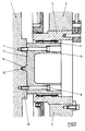
- a Rolling bearing In the hole of a frame 2 on the operator side (B side) is a Rolling bearing according to Fig. 1 arranged.
- the rolling bearing consists of one eccentrically designed outer ring 3, a central inner ring 5 and rolling elements 4 arranged therebetween and carries a cylinder 1.
- the inner ring 5 protrudes into the space between the two side frames towards a cylinder face 11 and takes the Pin stub 12 with circumferential centering 8 on the associated Centering 8 'on.
- the inner ring 5 also has a the cylinder 1 adjacent end face, which as a flat surface 7th is executed.
- the flat surface 7 is assigned to a cylinder shoulder 13 a flat surface 7 'is arranged.
- the neighboring flat areas 7 'and 7 form over several connecting elements 6, e.g. Screws, a detachable positive connection from cylinder 1 and inner ring 5 of storage.
- a cover 10 can be used as a protective device.
- the cylinder 1 no journal stub 12.
- a centering 9 is arranged, one on the circumference of the inner ring 5 located centering 9 'is assigned.
- the inner ring 5 has, as already described, a flat surface 7 on the Cylinder shoulder 13 is assigned a flat surface 7 '.
- About fasteners 6 is the releasable positive connection of Cylinder 1 and inner ring 5 formed as already described.
- the cylinder 3 shows a further embodiment of the storage according to the invention, which especially for cylinders or drums with low Weight or suitable for rollers.
- the cylinder e.g. a sheet-guiding drum, has a cylinder shoulder 13, in the center of the axis incorporated a conical centering 14 ' is.
- the centering 14 ' is assigned a centering tip 14 which is arranged on the flat surface 7 of the inner ring 5.
- the inner ring 5 consists, in this embodiment on the flat surface 7, of a Solid material.
- the inner ring 5 can continue as a solid shaft Centering tip 14 may be formed.
Landscapes
- Engineering & Computer Science (AREA)
- Mechanical Engineering (AREA)
- Rotary Presses (AREA)
- Rolls And Other Rotary Bodies (AREA)
- Sliding-Contact Bearings (AREA)
- Electroluminescent Light Sources (AREA)
Description
- Fig. 1
- die Zylinderlagerung mit Zentrierung am Zapfenstummel,
- Fig. 2
- die Zylinderlagerung mit Zentrierung in der Zylinderschulter,
- Fig. 3
- die Zylinderlagerung mit Zentrierung in der Zylinderachse.
- 1
- Zylinder
- 2
- Gestell
- 3
- Außenring
- 4
- Wälzkörper
- 5
- Innenring
- 6
- Verbindungselement
- 7
- Planfläche
- 7'
- Planfläche
- 8
- Zentrierung
- 8'
- Zentrierung
- 9
- Zentrierung
- 9'
- Zentrierung
- 10
- Abdeckung
- 11
- Zylinderstirnseite
- 12
- Zapfenstummel
- 13
- Zylinderschulter
- 14
- Zentrierspitze
- 14'
- Zentrierung
Claims (4)
- Lagerung mit Wälz- oder Gleitlager für Zylinder und Trommeln in Druckmaschinen, wobei
der Zylinder (1) mit einem Innenring (5) der in einem Gestell (2) aufgenommenen Wälz- oder Gleitlager durch eine Zentrierung (8, 8', 9, 9', 14, 14') und eine Planfläche (7, 7') lösbar formschlüssig mit Verbindungselementen (6) fixiert ist. - Lagerung nach Anspruch 1,
dadurch gekennzeichnet,
daß der Zylinder (1) einen Zapfenstummel (12) besitzt, der mit dem Innenring (5) die umfangsseitige Zentrierung (8, 8') bildet. - Lagerung nach Anspruch 1,
dadurch gekennzeichnet,
daß der Zylinder (1) innerhalb der Zylinderschulter (13) eine Zentrierung (9) aufweist, welcher der Innenring (5) mit einer Zentrierung (9') zugeordnet ist. - Lagerung nach Anspruch 1,
dadurch gekennzeichnet,
daß der Zylinder (1) in der Achsmitte eine Zentrierung (14') aufweist, die von einer am Innenring (5) angeordneten Zentrierspitze (14) aufgenommen ist.
Applications Claiming Priority (2)
| Application Number | Priority Date | Filing Date | Title |
|---|---|---|---|
| DE4406143A DE4406143C2 (de) | 1994-02-25 | 1994-02-25 | Lagerung für Zylinder und Trommeln in Druckmaschinen |
| DE4406143 | 1994-02-25 |
Publications (2)
| Publication Number | Publication Date |
|---|---|
| EP0669209A1 EP0669209A1 (de) | 1995-08-30 |
| EP0669209B1 true EP0669209B1 (de) | 1998-03-18 |
Family
ID=6511198
Family Applications (1)
| Application Number | Title | Priority Date | Filing Date |
|---|---|---|---|
| EP95100583A Expired - Lifetime EP0669209B1 (de) | 1994-02-25 | 1995-01-18 | Lagerung für Zylinder und Trommeln in Druckmaschinen |
Country Status (4)
| Country | Link |
|---|---|
| EP (1) | EP0669209B1 (de) |
| JP (1) | JP2839852B2 (de) |
| AT (1) | ATE164117T1 (de) |
| DE (2) | DE4406143C2 (de) |
Families Citing this family (1)
| Publication number | Priority date | Publication date | Assignee | Title |
|---|---|---|---|---|
| WO2008069708A1 (en) * | 2006-12-07 | 2008-06-12 | Aktiebolaget Skf | Bearing component and bearing arrangement comprising the bearing component |
Family Cites Families (8)
| Publication number | Priority date | Publication date | Assignee | Title |
|---|---|---|---|---|
| BE549419A (de) * | ||||
| DE755282C (de) * | 1942-04-03 | 1952-08-14 | Maschf Augsburg Nuernberg Ag | Lagerung des Gummizylinders einer Rotationsgummidruckmaschine |
| DE2024221A1 (de) * | 1969-06-30 | 1971-01-28 | VEB Polygraph Leipzig Kombinat fur polygraphische Maschinen und Ausrustun gen Betneb Druckmaschinenwerk PLAMAG Plauen, χ 9900 Plauen | Lager fur auswechselbare Druck maschinenzylinder, insbesondere Tief druck Formzylinder |
| GB1247649A (en) * | 1970-07-14 | 1971-09-29 | Polygraph Leipzig Betr Druckma | Bearing for interchangeable printing machine cylinders |
| DE3324811A1 (de) * | 1983-07-09 | 1985-01-17 | INA Wälzlager Schaeffler KG, 8522 Herzogenaurach | Waelzlagerung fuer die zapfen von gummizylindern in druckmaschinen |
| DE3708600A1 (de) * | 1987-03-17 | 1988-09-29 | Werner Jacob | Zweireihiges waelzlager |
| DE4227648A1 (de) * | 1992-08-21 | 1993-03-25 | Karl Peter Basenau | Metalldampflaser |
| DE4227643C2 (de) * | 1992-08-21 | 1996-01-11 | Roland Man Druckmasch | Lagerung für Zylinder und Trommeln in Druckmaschinen |
-
1994
- 1994-02-25 DE DE4406143A patent/DE4406143C2/de not_active Expired - Fee Related
-
1995
- 1995-01-18 AT AT95100583T patent/ATE164117T1/de not_active IP Right Cessation
- 1995-01-18 EP EP95100583A patent/EP0669209B1/de not_active Expired - Lifetime
- 1995-01-18 DE DE59501617T patent/DE59501617D1/de not_active Expired - Lifetime
- 1995-02-23 JP JP7035623A patent/JP2839852B2/ja not_active Expired - Fee Related
Also Published As
| Publication number | Publication date |
|---|---|
| JPH07256861A (ja) | 1995-10-09 |
| DE4406143C2 (de) | 1997-03-27 |
| DE59501617D1 (de) | 1998-04-23 |
| JP2839852B2 (ja) | 1998-12-16 |
| EP0669209A1 (de) | 1995-08-30 |
| DE4406143A1 (de) | 1995-08-31 |
| ATE164117T1 (de) | 1998-04-15 |
Similar Documents
| Publication | Publication Date | Title |
|---|---|---|
| EP0819550B1 (de) | Gummizylinderhülse, insbesondere für Offset-Rollenrotationsdruckmaschinen | |
| EP0894623B1 (de) | Druckwerk für eine Rollenrotationsdruckmaschine | |
| EP1025996A1 (de) | Klischeezylinder | |
| AT502694B1 (de) | Strangführungsrolle | |
| DE19649182C2 (de) | Druckzylinder | |
| EP0669209B1 (de) | Lagerung für Zylinder und Trommeln in Druckmaschinen | |
| DE2832966A1 (de) | Einrichtung zum drehfesten verbinden von mit wellen oder wellenzapfen umlaufenden maschinenteilen, beispielsweise walzen | |
| DE4205167A1 (de) | Als waermetauscher dienende walze | |
| EP0293670B1 (de) | Vorrichtung zum axialen Verschieben von sich drehenden Walzwerkswalzen | |
| EP0894545B1 (de) | Bandlaufrolle | |
| EP0586863B1 (de) | Lagerung für Zylinder und Trommeln in Druckmaschinen | |
| DE10144974B4 (de) | Walzgerüst zum Walzen von stab- oder rohrförmigem Gut | |
| EP1838469B1 (de) | Stützwalze für ein walzwerk | |
| DE2422036A1 (de) | Vorrichtung zum aufbringen einer zugkraft auf eine hohlwelle | |
| EP1530685B1 (de) | Anschlusselement zur verbindung von gelenkspindeln mit anschlussaggregaten, insbesondere trefferhalterung mit konischer zentrierung | |
| DE3531850A1 (de) | Trommel fuer kardiermaschinen | |
| DE1710498B2 (de) | Walze fuer die behandlung von flaechigem material, z.b. gewebebahnen | |
| DE3839101C1 (en) | Cylinder, particularly for the pressure treatment of webs of material | |
| AT403034B (de) | Walze für maschinen zur führung von bahnenförmigem flächigen material | |
| DE20003241U1 (de) | Rollenanordnung für einen Rollenförderer | |
| DE2037627A1 (de) | Rollgangsrolle mit Einzelantrieb | |
| AT389156B (de) | Kreuzgelenk | |
| DE1710498C3 (de) | Walze für die Behandlung von flächigem Material, z.B. Gewebebahnen | |
| DE8634527U1 (de) | Kreuzgelenk für eine hochbelastbare Gelenkwelle | |
| DE29721509U1 (de) | Elastische Walze für eine Kalanderanordnung |
Legal Events
| Date | Code | Title | Description |
|---|---|---|---|
| PUAI | Public reference made under article 153(3) epc to a published international application that has entered the european phase |
Free format text: ORIGINAL CODE: 0009012 |
|
| 17P | Request for examination filed |
Effective date: 19950206 |
|
| AK | Designated contracting states |
Kind code of ref document: A1 Designated state(s): AT BE CH DE ES FR GB IT LI |
|
| 17Q | First examination report despatched |
Effective date: 19960813 |
|
| GRAG | Despatch of communication of intention to grant |
Free format text: ORIGINAL CODE: EPIDOS AGRA |
|
| GRAG | Despatch of communication of intention to grant |
Free format text: ORIGINAL CODE: EPIDOS AGRA |
|
| GRAH | Despatch of communication of intention to grant a patent |
Free format text: ORIGINAL CODE: EPIDOS IGRA |
|
| GRAH | Despatch of communication of intention to grant a patent |
Free format text: ORIGINAL CODE: EPIDOS IGRA |
|
| GRAA | (expected) grant |
Free format text: ORIGINAL CODE: 0009210 |
|
| AK | Designated contracting states |
Kind code of ref document: B1 Designated state(s): AT BE CH DE ES FR GB IT LI |
|
| PG25 | Lapsed in a contracting state [announced via postgrant information from national office to epo] |
Ref country code: IT Free format text: LAPSE BECAUSE OF FAILURE TO SUBMIT A TRANSLATION OF THE DESCRIPTION OR TO PAY THE FEE WITHIN THE PRE;WARNING: LAPSES OF ITALIAN PATENTS WITH EFFECTIVE DATE BEFORE 2007 MAY HAVE OCCURRED AT ANY TIME BEFORE 2007. THE CORRECT EFFECTIVE DATE MAY BE DIFFERENT FROM THE ONE RECORDED.SCRIBED TIME-LIMIT Effective date: 19980318 Ref country code: ES Free format text: THE PATENT HAS BEEN ANNULLED BY A DECISION OF A NATIONAL AUTHORITY Effective date: 19980318 |
|
| REF | Corresponds to: |
Ref document number: 164117 Country of ref document: AT Date of ref document: 19980415 Kind code of ref document: T |
|
| ET | Fr: translation filed | ||
| REG | Reference to a national code |
Ref country code: CH Ref legal event code: NV Representative=s name: E. BLUM & CO. PATENTANWAELTE Ref country code: CH Ref legal event code: EP |
|
| GBT | Gb: translation of ep patent filed (gb section 77(6)(a)/1977) |
Effective date: 19980319 |
|
| REF | Corresponds to: |
Ref document number: 59501617 Country of ref document: DE Date of ref document: 19980423 |
|
| PLBI | Opposition filed |
Free format text: ORIGINAL CODE: 0009260 |
|
| PLBQ | Unpublished change to opponent data |
Free format text: ORIGINAL CODE: EPIDOS OPPO |
|
| PLBI | Opposition filed |
Free format text: ORIGINAL CODE: 0009260 |
|
| PG25 | Lapsed in a contracting state [announced via postgrant information from national office to epo] |
Ref country code: BE Free format text: LAPSE BECAUSE OF NON-PAYMENT OF DUE FEES Effective date: 19990131 |
|
| 26 | Opposition filed |
Opponent name: KOENIG & BAUER AKTIENGESELLSCHAFT Effective date: 19981217 |
|
| PLBF | Reply of patent proprietor to notice(s) of opposition |
Free format text: ORIGINAL CODE: EPIDOS OBSO |
|
| 26 | Opposition filed |
Opponent name: HEIDELBERGER DRUCKMASCHINEN AG Effective date: 19981216 Opponent name: KOENIG & BAUER AKTIENGESELLSCHAFT Effective date: 19981217 |
|
| PLBF | Reply of patent proprietor to notice(s) of opposition |
Free format text: ORIGINAL CODE: EPIDOS OBSO |
|
| BERE | Be: lapsed |
Owner name: MAN ROLAND DRUCKMASCHINEN A.G. Effective date: 19990131 |
|
| PLBO | Opposition rejected |
Free format text: ORIGINAL CODE: EPIDOS REJO |
|
| APAC | Appeal dossier modified |
Free format text: ORIGINAL CODE: EPIDOS NOAPO |
|
| APAE | Appeal reference modified |
Free format text: ORIGINAL CODE: EPIDOS REFNO |
|
| APAC | Appeal dossier modified |
Free format text: ORIGINAL CODE: EPIDOS NOAPO |
|
| REG | Reference to a national code |
Ref country code: GB Ref legal event code: IF02 |
|
| PGFP | Annual fee paid to national office [announced via postgrant information from national office to epo] |
Ref country code: CH Payment date: 20021218 Year of fee payment: 9 |
|
| PGFP | Annual fee paid to national office [announced via postgrant information from national office to epo] |
Ref country code: GB Payment date: 20021227 Year of fee payment: 9 |
|
| PGFP | Annual fee paid to national office [announced via postgrant information from national office to epo] |
Ref country code: FR Payment date: 20030110 Year of fee payment: 9 |
|
| APAC | Appeal dossier modified |
Free format text: ORIGINAL CODE: EPIDOS NOAPO |
|
| PLBN | Opposition rejected |
Free format text: ORIGINAL CODE: 0009273 |
|
| PLBP | Opposition withdrawn |
Free format text: ORIGINAL CODE: 0009264 |
|
| STAA | Information on the status of an ep patent application or granted ep patent |
Free format text: STATUS: OPPOSITION REJECTED |
|
| 27O | Opposition rejected |
Effective date: 20030430 |
|
| PG25 | Lapsed in a contracting state [announced via postgrant information from national office to epo] |
Ref country code: GB Free format text: LAPSE BECAUSE OF NON-PAYMENT OF DUE FEES Effective date: 20040118 |
|
| PG25 | Lapsed in a contracting state [announced via postgrant information from national office to epo] |
Ref country code: LI Free format text: LAPSE BECAUSE OF NON-PAYMENT OF DUE FEES Effective date: 20040131 Ref country code: CH Free format text: LAPSE BECAUSE OF NON-PAYMENT OF DUE FEES Effective date: 20040131 |
|
| GBPC | Gb: european patent ceased through non-payment of renewal fee |
Effective date: 20040118 |
|
| REG | Reference to a national code |
Ref country code: CH Ref legal event code: PL |
|
| PG25 | Lapsed in a contracting state [announced via postgrant information from national office to epo] |
Ref country code: FR Free format text: LAPSE BECAUSE OF NON-PAYMENT OF DUE FEES Effective date: 20040930 |
|
| REG | Reference to a national code |
Ref country code: FR Ref legal event code: ST |
|
| APAH | Appeal reference modified |
Free format text: ORIGINAL CODE: EPIDOSCREFNO |
|
| PGFP | Annual fee paid to national office [announced via postgrant information from national office to epo] |
Ref country code: AT Payment date: 20100114 Year of fee payment: 16 |
|
| PGFP | Annual fee paid to national office [announced via postgrant information from national office to epo] |
Ref country code: DE Payment date: 20110121 Year of fee payment: 17 |
|
| PG25 | Lapsed in a contracting state [announced via postgrant information from national office to epo] |
Ref country code: AT Free format text: LAPSE BECAUSE OF NON-PAYMENT OF DUE FEES Effective date: 20110118 |
|
| PG25 | Lapsed in a contracting state [announced via postgrant information from national office to epo] |
Ref country code: DE Free format text: LAPSE BECAUSE OF NON-PAYMENT OF DUE FEES Effective date: 20120801 |
|
| REG | Reference to a national code |
Ref country code: DE Ref legal event code: R119 Ref document number: 59501617 Country of ref document: DE Effective date: 20120801 |