EP0669497B1 - Dispositif pour l'incinération des composés nuisibles oxydables - Google Patents
Dispositif pour l'incinération des composés nuisibles oxydables Download PDFInfo
- Publication number
- EP0669497B1 EP0669497B1 EP95101127A EP95101127A EP0669497B1 EP 0669497 B1 EP0669497 B1 EP 0669497B1 EP 95101127 A EP95101127 A EP 95101127A EP 95101127 A EP95101127 A EP 95101127A EP 0669497 B1 EP0669497 B1 EP 0669497B1
- Authority
- EP
- European Patent Office
- Prior art keywords
- fuel
- flow
- combustion chamber
- supply
- media
- Prior art date
- Legal status (The legal status is an assumption and is not a legal conclusion. Google has not performed a legal analysis and makes no representation as to the accuracy of the status listed.)
- Expired - Lifetime
Links
- 150000001875 compounds Chemical class 0.000 title 1
- 239000000446 fuel Substances 0.000 claims abstract description 34
- 238000002485 combustion reaction Methods 0.000 claims abstract description 25
- 239000003344 environmental pollutant Substances 0.000 claims abstract description 11
- 231100000719 pollutant Toxicity 0.000 claims abstract description 11
- 238000009827 uniform distribution Methods 0.000 claims description 2
- 238000009826 distribution Methods 0.000 description 3
- 239000000203 mixture Substances 0.000 description 3
- 230000003647 oxidation Effects 0.000 description 3
- 238000007254 oxidation reaction Methods 0.000 description 3
- 241001156002 Anthonomus pomorum Species 0.000 description 2
- 230000000694 effects Effects 0.000 description 2
- 239000007789 gas Substances 0.000 description 2
- 238000000034 method Methods 0.000 description 2
- QVGXLLKOCUKJST-UHFFFAOYSA-N atomic oxygen Chemical compound [O] QVGXLLKOCUKJST-UHFFFAOYSA-N 0.000 description 1
- 230000015572 biosynthetic process Effects 0.000 description 1
- 238000002474 experimental method Methods 0.000 description 1
- 150000002430 hydrocarbons Chemical class 0.000 description 1
- 239000007788 liquid Substances 0.000 description 1
- 238000004519 manufacturing process Methods 0.000 description 1
- 239000001301 oxygen Substances 0.000 description 1
- 229910052760 oxygen Inorganic materials 0.000 description 1
- 238000005192 partition Methods 0.000 description 1
- 230000035515 penetration Effects 0.000 description 1
Images

Classifications
-
- F—MECHANICAL ENGINEERING; LIGHTING; HEATING; WEAPONS; BLASTING
- F23—COMBUSTION APPARATUS; COMBUSTION PROCESSES
- F23G—CREMATION FURNACES; CONSUMING WASTE PRODUCTS BY COMBUSTION
- F23G7/00—Incinerators or other apparatus for consuming industrial waste, e.g. chemicals
- F23G7/06—Incinerators or other apparatus for consuming industrial waste, e.g. chemicals of waste gases or noxious gases, e.g. exhaust gases
-
- F—MECHANICAL ENGINEERING; LIGHTING; HEATING; WEAPONS; BLASTING
- F23—COMBUSTION APPARATUS; COMBUSTION PROCESSES
- F23D—BURNERS
- F23D14/00—Burners for combustion of a gas, e.g. of a gas stored under pressure as a liquid
- F23D14/20—Non-premix gas burners, i.e. in which gaseous fuel is mixed with combustion air on arrival at the combustion zone
- F23D14/22—Non-premix gas burners, i.e. in which gaseous fuel is mixed with combustion air on arrival at the combustion zone with separate air and gas feed ducts, e.g. with ducts running parallel or crossing each other
- F23D14/24—Non-premix gas burners, i.e. in which gaseous fuel is mixed with combustion air on arrival at the combustion zone with separate air and gas feed ducts, e.g. with ducts running parallel or crossing each other at least one of the fluids being submitted to a swirling motion
Definitions
- the invention relates to a device for burning contained in a media stream oxidizable pollutants.
- the device consists of a combustion chamber as well as in these opening channels for the supply of the preheated media stream and Lines for the supply of gas or gas required for the combustion of pollutants vaporous fuel.
- the channels for the media flow supply exist from axially parallel to each other via a combustion chamber front side in approximately uniform Distribution arranged nozzle, which the combustion chamber with a prechamber connect, the nozzles opening in the plane of the combustion chamber face.
- a line for the fuel supply is arranged concentrically in each nozzle.
- Such a device is known from EP 0 572 693 A1.
- the one used in it Burner is provided with several concentrically arranged ring channels for feeding the oxygen-containing polluted media stream and the gaseous or vaporous Fuel in the combustion chamber.
- the one loaded with pollutants The ring channel supplying media flow is provided with swirl blades and by one Surround fuel supply channel.
- the known burner is particularly complex in the production and still limits the desired intensive mixing with the polluted medium and the fuel on ring zones.
- a burner is known from GB-A-2 178 839, but in which Swirl principle is not realized. Instead, a hole emerges from the holes in a front panel Burner housing the media stream essentially linear. This is the fuel fed via a single centrally located line. The end of the feed line is closed, so that the fuel flow through four evenly over the Circumferentially distributed holes in the jacket of the supply line must emerge.
- Burner should therefore have a single supply line for the fuel to one if possible lead intimate mixing with the media flow supplied through holes. The quality of the mixing in such training is naturally very inadequate. At most, it happens with the media flows that come from the fuel supply leak out adjacent holes, for an acceptable mix.
- the invention is based, for a device of the initially described object
- a combustion chamber with little effort can be produced and particularly intensive mixing even with large volume flows the medium loaded with the pollutants and the fuel directly allows when entering the combustion chamber, so that the mixing zone and shorten the residence time of the medium can be further reduced with the same burnout ratio.
- a device in the preamble of the claim 1 mentioned type which according to the invention is the characteristic in its Features specified features.
- the mixing zone is also an induced one
- Burner are made smaller by the largest possible number Burner replaced, which are parallel to each other via a combustion chamber front side in even distribution are arranged.
- the assigned to each burner unit Swirl blades cause a highly turbulent swirl of the rays, which causes the intimate Mixing of the medium with the respective burner flame optimized and consequently the thermal oxidation of the pollutants contained in the medium is accelerated.
- Another advantage of the device according to the invention is the high flame stability the burner with variable volume flows.
- the radial outflow direction of the fuel reduces the risk of the burner flames tearing off larger volume flows.
- the swirl flow also almost leaves the volume flow independent flame pattern with a minimal combustion chamber penetration depth.
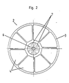
- a combustion chamber face 1 is equipped with 19 individual burner units 2. These are arranged axially parallel close to each other and extend in the essentially over the entire surface of the combustion chamber face 1.
- each individual burner unit comprises 2 a nozzle 3, in which a ring of swirl blades 4 is arranged.
- a hub 5 is provided concentrically in the nozzle 3 and has an axial bore 6, start from the branch lines 7 formed by radial bores. From one of these opens on the vacuum side of a swirl vane 4 The line 8 connected to the bore 6 becomes the single burner unit 2 with fuel provided.
- a media stream loaded with oxidizable pollutants is not shown Heat exchanger preheated and passed through the nozzle 3. Issue the swirl blades 4 the media flow an intense swirl. This creates a highly turbulent Flow field with an extremely short mixing zone.
- the device according to the invention can be operated with relatively low flame temperatures, as a result of which the NO x formation in the media stream is reduced.
Landscapes
- Engineering & Computer Science (AREA)
- Mechanical Engineering (AREA)
- General Engineering & Computer Science (AREA)
- Environmental & Geological Engineering (AREA)
- Combustion & Propulsion (AREA)
- Chemical & Material Sciences (AREA)
- Gas Burners (AREA)
- Gasification And Melting Of Waste (AREA)
- Pre-Mixing And Non-Premixing Gas Burner (AREA)
- Processing Of Solid Wastes (AREA)
- Combustion Of Fluid Fuel (AREA)
- Incineration Of Waste (AREA)
- Chimneys And Flues (AREA)
Claims (5)
- Dispositif d'incinération de polluants oxydables contenus dans un courant de fluide, constitué d'une chambre de combustion ainsi que de gaines débouchant dans cette dernière, pour amener le courant de fluide préchauffé, ainsi que de conduites pour amener le combustible sous forme de gaz ou de vapeur, nécessaire à l'incinération des polluants, dans lequelcaractérisé en ce que :les gaines destinées à l'amenée du courant de fluide sont constituées de tubulures (3), dont les axes sont parallèles les uns aux autres, disposées selon une répartition presque uniforme sur une face frontale (1) de la chambre de combustion, tubulures qui relient la chambre de combustion à une chambre de précombustion, les tubulures (3) débouchant dans le plan de la face frontale (1) de la chambre de combustion,dans chaque tubulure (3), une conduite (8) destinée à l'amenée du combustible est disposée en position concentrique, etdes aubes de turbulence (4) sont disposées dans l'espace annulaire défini par chaque tubulure (3) et un moyeu (5),des conduites de dérivation radiales (7), qui débouchent sur la face en dépression des aubes de turbulence (4), partent de chaque conduite (8) destinée à l'amenée du combustible, età chaque aube de turbulence (4) est affectée une conduite de dérivation (7).
- Dispositif selon la revendication 1, caractérisé en ce que chaque tubulure (3) et un certain nombre de conduites de dérivation (7), pourvues de buses de brûleur au niveau de leurs embouchures, forment une unité (2) de brûleurs individuels, et l'ensemble des unités (2) de brûleurs individuels ont les mêmes dimensions.
- Dispositif selon la revendication 1 ou 2, caractérisé en ce que les conduites (8) destinées à l'amenée du combustible communiquent par l'intermédiaire de conduites de dérivation avec une conduite centrale d'alimentation de combustible.
- Dispositif selon l'une des revendications 1 à 3, caractérisé en ce que les tubulures (3) présentent une résistance à l'écoulement de 400 à 1500 et de préférence de 600 à 1200 P, les unités (2) de brûleurs individuels étant globalement configurées pour traiter un débit volumique compris entre 100 et 5000 m3 normaux/h.
- Dispositif selon l'une des revendications 1 à 4, caractérisé en ce que le nombre des unités (2) de brûleurs individuels recevant chacune le courant de fluide et le combustible, est variable.
Applications Claiming Priority (2)
| Application Number | Priority Date | Filing Date | Title |
|---|---|---|---|
| DE4406369A DE4406369C2 (de) | 1994-02-26 | 1994-02-26 | Einrichtung zum Verbrennen von oxidierbaren Schadstoffen |
| DE4406369 | 1994-02-26 |
Publications (3)
| Publication Number | Publication Date |
|---|---|
| EP0669497A2 EP0669497A2 (fr) | 1995-08-30 |
| EP0669497A3 EP0669497A3 (fr) | 1996-05-08 |
| EP0669497B1 true EP0669497B1 (fr) | 1999-07-07 |
Family
ID=6511326
Family Applications (1)
| Application Number | Title | Priority Date | Filing Date |
|---|---|---|---|
| EP95101127A Expired - Lifetime EP0669497B1 (fr) | 1994-02-26 | 1995-01-27 | Dispositif pour l'incinération des composés nuisibles oxydables |
Country Status (4)
| Country | Link |
|---|---|
| EP (1) | EP0669497B1 (fr) |
| AT (1) | ATE182001T1 (fr) |
| DE (2) | DE4406369C2 (fr) |
| ES (1) | ES2133595T3 (fr) |
Families Citing this family (2)
| Publication number | Priority date | Publication date | Assignee | Title |
|---|---|---|---|---|
| IT1315743B1 (it) * | 2000-10-03 | 2003-03-18 | Sit La Precisa Spa | Dispositivo miscelatore aria-gas perfezionato. |
| DE10237604B4 (de) | 2002-08-16 | 2006-07-06 | Eisenmann Maschinenbau Gmbh & Co. Kg | Nachverbrennungseinrichtung mit einem Brenner |
Family Cites Families (7)
| Publication number | Priority date | Publication date | Assignee | Title |
|---|---|---|---|---|
| CH451380A (de) * | 1964-06-22 | 1968-05-15 | Fuel Firing Ltd | Brenner |
| DE2319194A1 (de) * | 1973-04-16 | 1974-10-24 | Konstantin Sergeewitsc Pirogow | Gasbrenner |
| JPS5672119A (en) * | 1979-11-20 | 1981-06-16 | Ishikawajima Harima Heavy Ind Co Ltd | Temperature compensation method of steel product and its apparatus |
| US4544350A (en) * | 1982-10-27 | 1985-10-01 | Vista Chemical Company | Burner apparatus for simultaneously incinerating liquid, dry gas and wet gas streams |
| GB2178839B (en) * | 1985-08-06 | 1989-08-16 | British Petroleum Co Plc | Combustor |
| DE8905865U1 (de) * | 1989-04-20 | 1989-10-12 | Budapesti Müszaki Egyetem, Budapest | Brenner zur Verbrennung von gasförmigen und/oder flüssigen Brennstoffen |
| EP0572693B1 (fr) * | 1992-06-02 | 1994-09-07 | Leobersdorfer Maschinenfabrik AG | Brûleur pour la combustion d'un milieu contaminé |
-
1994
- 1994-02-26 DE DE4406369A patent/DE4406369C2/de not_active Expired - Fee Related
-
1995
- 1995-01-27 ES ES95101127T patent/ES2133595T3/es not_active Expired - Lifetime
- 1995-01-27 AT AT95101127T patent/ATE182001T1/de not_active IP Right Cessation
- 1995-01-27 EP EP95101127A patent/EP0669497B1/fr not_active Expired - Lifetime
- 1995-01-27 DE DE59506323T patent/DE59506323D1/de not_active Expired - Fee Related
Also Published As
| Publication number | Publication date |
|---|---|
| ATE182001T1 (de) | 1999-07-15 |
| ES2133595T3 (es) | 1999-09-16 |
| EP0669497A2 (fr) | 1995-08-30 |
| DE59506323D1 (de) | 1999-08-12 |
| EP0669497A3 (fr) | 1996-05-08 |
| DE4406369C2 (de) | 1997-11-27 |
| DE4406369A1 (de) | 1995-08-31 |
Similar Documents
| Publication | Publication Date | Title |
|---|---|---|
| DE69515109T2 (de) | Verfahren und Vorrichtung zum Verbrennen sauerstoffhaltiger Bestandteile in einem Prozessgas | |
| DE69409428T2 (de) | Zweistoffbrenner mit sehr niedrigem NOx-Ausstoss | |
| DE3690574C2 (de) | Vorrichtung zum Erhitzen von Sauerstoff | |
| DE2825431C2 (de) | Vorrichtung zur Zufuhr von Luft und Brennstoff in die Brennkammer eines Gasturbinentriebwerkes | |
| DE2143012C3 (de) | Brenneranordnung bei einer Gasturbinen-Brennkammer | |
| DE2828826C2 (fr) | ||
| EP1064498B1 (fr) | Bruleur pour une turbine a gas | |
| DE3518080C2 (fr) | ||
| DE3880251T2 (de) | Betreibungsmethode eines wirbelstrombrenners mit abgestufter luftzufuhr. | |
| DE2461078A1 (de) | Verfahren zur verminderung von schadstoffen bei verbrennungsvorgaengen und vorrichtung zur durchfuehrung desselben | |
| DE1551637A1 (de) | Heizvorrichtung | |
| EP0907868B1 (fr) | Bruleur | |
| DE1501802A1 (de) | Brenner | |
| EP0483554B1 (fr) | Procédé pour la réduction au minimum des émissions de NOx dans une combustion | |
| EP0430011B1 (fr) | Brûleur pour la combustion de combustibles liquides ou gazeux | |
| WO2006040255A1 (fr) | Bruleur pour combustibles fluides et procede permettant de faire fonctionner un bruleur de ce type | |
| DE2410141B2 (de) | Brenner fuer fluide brennstoffe | |
| EP1754937B1 (fr) | Tête de brûleur et procédé pour brûler du combustible | |
| DE4406369C2 (de) | Einrichtung zum Verbrennen von oxidierbaren Schadstoffen | |
| DE60115773T2 (de) | Gasbrenner mit erhöhter Leistung | |
| EP0014221B1 (fr) | Brûleur tunnel à gaz destiné à porter des fours de fusion ou des creusets à la température voulue | |
| DE10237604B4 (de) | Nachverbrennungseinrichtung mit einem Brenner | |
| DE2638878A1 (de) | Brennkammer fuer fluessige oder gasfoermige brennstoffe | |
| EP0190660A2 (fr) | Brûleur à air soufflé sous faible pression | |
| DE8308076U1 (de) | Vorrichtung zum Verbrennen fester Brennstoffe, insbesondere Kohle, Torf od. dgl. |
Legal Events
| Date | Code | Title | Description |
|---|---|---|---|
| PUAI | Public reference made under article 153(3) epc to a published international application that has entered the european phase |
Free format text: ORIGINAL CODE: 0009012 |
|
| AK | Designated contracting states |
Kind code of ref document: A2 Designated state(s): AT CH DE ES FR GB IT LI NL SE |
|
| PUAL | Search report despatched |
Free format text: ORIGINAL CODE: 0009013 |
|
| AK | Designated contracting states |
Kind code of ref document: A3 Designated state(s): AT CH DE ES FR GB IT LI NL SE |
|
| 17P | Request for examination filed |
Effective date: 19960410 |
|
| 17Q | First examination report despatched |
Effective date: 19971104 |
|
| GRAG | Despatch of communication of intention to grant |
Free format text: ORIGINAL CODE: EPIDOS AGRA |
|
| GRAG | Despatch of communication of intention to grant |
Free format text: ORIGINAL CODE: EPIDOS AGRA |
|
| GRAH | Despatch of communication of intention to grant a patent |
Free format text: ORIGINAL CODE: EPIDOS IGRA |
|
| GRAH | Despatch of communication of intention to grant a patent |
Free format text: ORIGINAL CODE: EPIDOS IGRA |
|
| GRAA | (expected) grant |
Free format text: ORIGINAL CODE: 0009210 |
|
| AK | Designated contracting states |
Kind code of ref document: B1 Designated state(s): AT CH DE ES FR GB IT LI NL SE |
|
| REF | Corresponds to: |
Ref document number: 182001 Country of ref document: AT Date of ref document: 19990715 Kind code of ref document: T |
|
| REG | Reference to a national code |
Ref country code: CH Ref legal event code: NV Representative=s name: PATENTANWAELTE GEORG ROEMPLER UND ALDO ROEMPLER Ref country code: CH Ref legal event code: EP |
|
| REF | Corresponds to: |
Ref document number: 59506323 Country of ref document: DE Date of ref document: 19990812 |
|
| ET | Fr: translation filed | ||
| REG | Reference to a national code |
Ref country code: ES Ref legal event code: FG2A Ref document number: 2133595 Country of ref document: ES Kind code of ref document: T3 |
|
| GBT | Gb: translation of ep patent filed (gb section 77(6)(a)/1977) |
Effective date: 19990914 |
|
| PLBE | No opposition filed within time limit |
Free format text: ORIGINAL CODE: 0009261 |
|
| STAA | Information on the status of an ep patent application or granted ep patent |
Free format text: STATUS: NO OPPOSITION FILED WITHIN TIME LIMIT |
|
| 26N | No opposition filed | ||
| PGFP | Annual fee paid to national office [announced via postgrant information from national office to epo] |
Ref country code: FR Payment date: 20011123 Year of fee payment: 8 |
|
| PGFP | Annual fee paid to national office [announced via postgrant information from national office to epo] |
Ref country code: DE Payment date: 20011206 Year of fee payment: 8 |
|
| PGFP | Annual fee paid to national office [announced via postgrant information from national office to epo] |
Ref country code: AT Payment date: 20011221 Year of fee payment: 8 |
|
| REG | Reference to a national code |
Ref country code: GB Ref legal event code: IF02 |
|
| PGFP | Annual fee paid to national office [announced via postgrant information from national office to epo] |
Ref country code: SE Payment date: 20020114 Year of fee payment: 8 |
|
| PGFP | Annual fee paid to national office [announced via postgrant information from national office to epo] |
Ref country code: GB Payment date: 20020117 Year of fee payment: 8 |
|
| PGFP | Annual fee paid to national office [announced via postgrant information from national office to epo] |
Ref country code: ES Payment date: 20020124 Year of fee payment: 8 |
|
| PGFP | Annual fee paid to national office [announced via postgrant information from national office to epo] |
Ref country code: NL Payment date: 20020131 Year of fee payment: 8 |
|
| PGFP | Annual fee paid to national office [announced via postgrant information from national office to epo] |
Ref country code: CH Payment date: 20020430 Year of fee payment: 8 |
|
| PG25 | Lapsed in a contracting state [announced via postgrant information from national office to epo] |
Ref country code: GB Free format text: LAPSE BECAUSE OF NON-PAYMENT OF DUE FEES Effective date: 20030127 Ref country code: AT Free format text: LAPSE BECAUSE OF NON-PAYMENT OF DUE FEES Effective date: 20030127 |
|
| PG25 | Lapsed in a contracting state [announced via postgrant information from national office to epo] |
Ref country code: SE Free format text: LAPSE BECAUSE OF NON-PAYMENT OF DUE FEES Effective date: 20030128 Ref country code: ES Free format text: LAPSE BECAUSE OF NON-PAYMENT OF DUE FEES Effective date: 20030128 |
|
| PG25 | Lapsed in a contracting state [announced via postgrant information from national office to epo] |
Ref country code: LI Free format text: LAPSE BECAUSE OF NON-PAYMENT OF DUE FEES Effective date: 20030131 Ref country code: CH Free format text: LAPSE BECAUSE OF NON-PAYMENT OF DUE FEES Effective date: 20030131 |
|
| PG25 | Lapsed in a contracting state [announced via postgrant information from national office to epo] |
Ref country code: NL Free format text: LAPSE BECAUSE OF NON-PAYMENT OF DUE FEES Effective date: 20030801 Ref country code: DE Free format text: LAPSE BECAUSE OF NON-PAYMENT OF DUE FEES Effective date: 20030801 |
|
| EUG | Se: european patent has lapsed | ||
| REG | Reference to a national code |
Ref country code: CH Ref legal event code: PL |
|
| GBPC | Gb: european patent ceased through non-payment of renewal fee | ||
| PG25 | Lapsed in a contracting state [announced via postgrant information from national office to epo] |
Ref country code: FR Free format text: LAPSE BECAUSE OF NON-PAYMENT OF DUE FEES Effective date: 20030930 |
|
| NLV4 | Nl: lapsed or anulled due to non-payment of the annual fee |
Effective date: 20030801 |
|
| REG | Reference to a national code |
Ref country code: FR Ref legal event code: ST |
|
| REG | Reference to a national code |
Ref country code: ES Ref legal event code: FD2A Effective date: 20030128 |
|
| PG25 | Lapsed in a contracting state [announced via postgrant information from national office to epo] |
Ref country code: IT Free format text: LAPSE BECAUSE OF NON-PAYMENT OF DUE FEES;WARNING: LAPSES OF ITALIAN PATENTS WITH EFFECTIVE DATE BEFORE 2007 MAY HAVE OCCURRED AT ANY TIME BEFORE 2007. THE CORRECT EFFECTIVE DATE MAY BE DIFFERENT FROM THE ONE RECORDED. Effective date: 20050127 |