EP0669523B1 - Anordnung zur Messung des Flüssigkeitsniveaus in einem Behälter - Google Patents
Anordnung zur Messung des Flüssigkeitsniveaus in einem Behälter Download PDFInfo
- Publication number
- EP0669523B1 EP0669523B1 EP95400348A EP95400348A EP0669523B1 EP 0669523 B1 EP0669523 B1 EP 0669523B1 EP 95400348 A EP95400348 A EP 95400348A EP 95400348 A EP95400348 A EP 95400348A EP 0669523 B1 EP0669523 B1 EP 0669523B1
- Authority
- EP
- European Patent Office
- Prior art keywords
- float
- magnet
- chamber
- pump
- level
- Prior art date
- Legal status (The legal status is an assumption and is not a legal conclusion. Google has not performed a legal analysis and makes no representation as to the accuracy of the status listed.)
- Expired - Lifetime
Links
- 239000007788 liquid Substances 0.000 title claims description 24
- 239000002184 metal Substances 0.000 claims description 4
- 229910052751 metal Inorganic materials 0.000 claims description 4
- 238000011084 recovery Methods 0.000 claims description 4
- 229910000863 Ferronickel Inorganic materials 0.000 claims description 3
- 239000002775 capsule Substances 0.000 claims 3
- 238000006073 displacement reaction Methods 0.000 claims 1
- 238000001514 detection method Methods 0.000 description 11
- XLYOFNOQVPJJNP-UHFFFAOYSA-N water Substances O XLYOFNOQVPJJNP-UHFFFAOYSA-N 0.000 description 6
- 238000004378 air conditioning Methods 0.000 description 3
- 230000005494 condensation Effects 0.000 description 3
- 238000009833 condensation Methods 0.000 description 3
- 238000009434 installation Methods 0.000 description 3
- 230000005484 gravity Effects 0.000 description 2
- RYGMFSIKBFXOCR-UHFFFAOYSA-N Copper Chemical compound [Cu] RYGMFSIKBFXOCR-UHFFFAOYSA-N 0.000 description 1
- 241000195493 Cryptophyta Species 0.000 description 1
- 235000014676 Phragmites communis Nutrition 0.000 description 1
- 239000003570 air Substances 0.000 description 1
- 239000012080 ambient air Substances 0.000 description 1
- 229910052802 copper Inorganic materials 0.000 description 1
- 239000010949 copper Substances 0.000 description 1
- 238000010586 diagram Methods 0.000 description 1
- 239000004519 grease Substances 0.000 description 1
- 230000007257 malfunction Effects 0.000 description 1
- 239000000463 material Substances 0.000 description 1
- 238000005259 measurement Methods 0.000 description 1
- 239000003507 refrigerant Substances 0.000 description 1
Images


Classifications
-
- F—MECHANICAL ENGINEERING; LIGHTING; HEATING; WEAPONS; BLASTING
- F28—HEAT EXCHANGE IN GENERAL
- F28B—STEAM OR VAPOUR CONDENSERS
- F28B9/00—Auxiliary systems, arrangements, or devices
- F28B9/08—Auxiliary systems, arrangements, or devices for collecting and removing condensate
-
- G—PHYSICS
- G01—MEASURING; TESTING
- G01F—MEASURING VOLUME, VOLUME FLOW, MASS FLOW OR LIQUID LEVEL; METERING BY VOLUME
- G01F23/00—Indicating or measuring liquid level or level of fluent solid material, e.g. indicating in terms of volume or indicating by means of an alarm
- G01F23/30—Indicating or measuring liquid level or level of fluent solid material, e.g. indicating in terms of volume or indicating by means of an alarm by floats
- G01F23/64—Indicating or measuring liquid level or level of fluent solid material, e.g. indicating in terms of volume or indicating by means of an alarm by floats of the free float type without mechanical transmission elements
- G01F23/72—Indicating or measuring liquid level or level of fluent solid material, e.g. indicating in terms of volume or indicating by means of an alarm by floats of the free float type without mechanical transmission elements using magnetically actuated indicating means
- G01F23/74—Indicating or measuring liquid level or level of fluent solid material, e.g. indicating in terms of volume or indicating by means of an alarm by floats of the free float type without mechanical transmission elements using magnetically actuated indicating means for sensing changes in level only at discrete points
-
- F—MECHANICAL ENGINEERING; LIGHTING; HEATING; WEAPONS; BLASTING
- F24—HEATING; RANGES; VENTILATING
- F24F—AIR-CONDITIONING; AIR-HUMIDIFICATION; VENTILATION; USE OF AIR CURRENTS FOR SCREENING
- F24F13/00—Details common to, or for air-conditioning, air-humidification, ventilation or use of air currents for screening
- F24F13/22—Means for preventing condensation or evacuating condensate
Definitions
- the present invention relates to a device for detecting liquid levels in a condensate recovery tank, intended to be connected to the control of a condensate lifting pump.
- condensate lifting pumps are provided with control systems which automatically start the pump when the liquid level reaches a predetermined maximum level and which automatically stop the operation of the pump when the level of the condensing liquid in the tank drops to a minimum level.
- control systems are connected to liquid level detection devices in the tank which emit a first signal when the condensate level reaches the maximum permitted level and a second signal when the condensate level reaches the minimum authorized level.
- Level detection devices are already known which include electrodes located at different levels in the tank or the tank. Water ensures the passage of a micro-current from one electrode to the other. This micro-current starts or stops the pump depending on the level of the condensate. This solution is compact, but, on the other hand, the quality of the water influences the value of the micro-currents and the presence of algae or grease on the surface of the condensates can cause malfunctions.
- devices for detecting levels of liquids which comprise a float raised by the liquid, a magnet carried by the float and at least two switches with sealed contacts, in the form of bulbs, arranged at the in the vicinity of the path of said magnet and offset vertically, each of said switches controlling the closing of an electrical circuit connected to said control when it is subjected to the magnetic field of the magnet.
- the bulbs are arranged vertically or are placed above the float.
- the detection device has a height which is at least equal to the length of a bulb, increased by the difference between the minimum and maximum authorized levels of the condensate in the tank. This height can be greater than 60mm, especially when a third bulb connected to a device is provided to detect a safety level higher than the maximum level of pump start-up. In certain types of air conditioners (ceiling lights, mini wall splits) that require a shallow tank or the placement of the level sensor at the end of the condensate drain, this minimum possible height or the possible size of the sensor housing can be unacceptable.
- FR-A-2 683 316 shows such a device in which the bulbs are arranged vertically in a guide tube of an annular float carrying an annular magnet.
- EP-A-397 338 relates to a device for precisely measuring the level of liquid in a tank of a motor vehicle.
- This device also comprises an annular magnet carried by a cylindrical float which rolls on a vertical wall arranged near a superposition of horizontal bulbs. The purpose of this arrangement is not to reduce the height of the device, but to increase the accuracy of the measurements.
- the object of the present invention is to provide a device for detecting the level of liquid in a condensate recovery tank or at the end of the drainage drain which is efficient and compact in height.
- the invention therefore relates to a device for detecting liquid levels, intended to be connected to the control of a condensate lifting pump in order to put the pump into operation when the liquid level reaches a maximum authorized level and to stop the operation of the pump when the liquid level drops to a minimum level, said device comprising a float lifted by said liquid and guided vertically, a magnet carried by said float, and at least two switches with sealed contacts in a bulb, arranged in the vicinity of the path of said magnet and vertically offset, each of said switches ensuring the closing of an electrical circuit connected to the control when it is in the magnetic field of said magnet.
- this detection device is characterized in that the said bulbs are arranged horizontally in a vertical plane parallel to the movement of the float, that the float has a generally parallelepiped shape, that the magnet is disposed in the vicinity of a lateral edge of the float and that a metal bar is provided on the edge of the float opposite to said magnet.
- This position makes it possible to significantly reduce the height of the level detection device, while providing successive information (start, stop, alarm).
- This magnetic field deflector consists of a ferro-nickel wire.
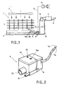
- FIG. 1 shows an air conditioning installation 1 which includes an exchanger 2 in which a refrigerant circulates and which is intended to cool ambient air driven in movement by a fan 3.
- a tank 4 for recovering condensation water which flows by gravity along the external walls of the exchanger 2.
- the tank 4 has a lateral opening where a condensate evacuation pipe 5 bis.
- a device 6 for detecting liquid levels.
- This device 6 is connected by two electrical circuits 7a, 7b to a device 8 for controlling a lifting pump 9.
- the condensate pump 9 is connected to the tank 4 by a flexible suction pipe 10 and discharges the pumped liquid to a manifold, not shown in the drawing, by a discharge pipe 11.
- the communication between the flexible pipe 10 d 'suction and the tank 4 is done through the device 6 for detecting liquid levels as described below.
- the electrical circuit 7a When the liquid level in the tank 4 or the piping 5 bis reaches the maximum level Ma, the electrical circuit 7a is closed and the device 8 control operates the pump 9. The condensate is sucked through the flexible pipe 10 and discharged to the collector.
- the level detection device 6 comprising a contact switch sealed in a bulb can also be connected by an electrical circuit 12 to a trigger device 13 when a security level Ns, greater than Ma, is reached by the liquid in the tray 4.
- Figures 2 and 3 show in detail the device 6 for detecting levels according to the invention.
- This detection device 6 comprises a housing 14 of generally parallelepiped shape, closed by an upper cover 15.
- the housing 14 has a bottom 16, four side walls 17a, 17b, 17c, 17d, a transverse wall 18 and a vertical grid 19 perpendicular to the transverse wall 18.
- the interior of the housing 14 is thus divided into three chambers 20, 21 and 22 which are closed together by the cover 15.
- a float 23 of parallelepipedal shape which carries a magnet 24 near the transverse wall 18.
- the second chamber 21 communicates with the first chamber 20 by the grid 19. It also communicates with the tank 4 or the piping 5 bis and with the pump 9.
- a filter element 27 fills the second chamber 21.
- a small orifice through the wall partially closing the bottom of the endpiece 25 and the chamber 20 provides water admission directly from the tank 4 or from the piping 5 bis to the chamber 20 in the event of clogging of the filter element 27 .
- a metal bar 28 made of copper for example, which has a weight close to the weight of the magnet 24.
- the housing 14 and the cover 15 are made of a plastic material, the cover 15 is fixed to the housing by a screw 15a.
- a vent hole 29 is provided in the cover 15 above the first chamber 20. This vent hole 29 can be closed off by the upper face of the float 23.
- a bulb mounting plate 30 which encloses a switch with sealed contacts and sensitive to a magnetic field. These bulbs are of the "REED SWITCH” type. This plate 30 is mounted vertically and is held in grooves 32 provided in the walls 17b and 17d.
- the bulbs 31 which can be two in number or three in number, are mounted horizontally on the plate 30 in a vertical plane close to the first chamber 20.
- the middle bulb 31a allows the electrical circuit 7b to be closed when 'it is subjected to the magnetic field of the magnet 24.
- the upper bulb 31b allows the closing of the electrical circuit 7a when it is subjected to the magnetic field of the magnet 24.
- the lower bulb 31c which is optional, allows activate the electrical circuit 12 connected to the device 13 for triggering an alarm.
- This bulb 30c is activated when the float 23 is in the low position, when the float reaches the level Ns, it is no longer activated and the circuit 12 is activated.
- the three ampoules 31a, 31b, 31c are arranged in locations corresponding respectively to the liquid levels Mi, Ma, Ns.
- Ferro-nickel wires 32a and 32b can be placed between the bulbs 31a, 31b and 31c, in particular when the bulbs are very close. These wires make it possible to modify the magnetic field of the magnet 24.
- FIG. 4 shows the correspondence between the positions of the diodes 31a, 31b, 31c and of the levels Mi, Ma, Ns to be detected.
- the magnet 24 is advantageously in the form of a metal bar.
Landscapes
- Engineering & Computer Science (AREA)
- Mechanical Engineering (AREA)
- General Engineering & Computer Science (AREA)
- Physics & Mathematics (AREA)
- Fluid Mechanics (AREA)
- General Physics & Mathematics (AREA)
- Level Indicators Using A Float (AREA)
Claims (5)
- Vorrichtung zum Feststellen von Niveaus einer Flüssigkeit in einem Kondensatauffangbehälter, wobei die Vorrichtung mit der Steuerung (8) einer Kondensathubpumpe (9) verbindbar ist, um die Pumpe einzuschalten, wenn das Flüssigkeitsniveau ein zulässiges Maximumniveau (Ma) erreicht und den Betrieb der Pumpe (9) abzuschalten, wenn das Flüssigkeitsniveau wieder auf ein Minimumniveau (Mi) absinkt, die Vorrichtung (6) einen von der Flüssigkeit angehobenen und senkrecht geführten Schwimmer (23), einen vom Schwimmer (23) getragenen Magneten (24) und wenigstens zwei Schalter (31a, 31b) mit in einem Röhrchen versiegelten Kontakten aufweist, die in der Nähe der Bewegungsbahn des Magneten (24) und senkrecht versetzt angeordnet sind, wobei jeder der Schalter einen mit der Steuerung (8) verbundenen elektrischen Kreis schließt, wenn er sich im Magnetfeld des Magneten (24) befindet,
dadurch gekennzeichnet, daß die Röhrchen (31a, 31b) waagerecht in einer zur Bewegung des Schwimmers parallelen senkrechten Ebene angeordnet sind, daß der Schwimmer (23) von ungefähr quaderförmiger Gestalt ist, daß der Magnet (24) in der Nähe eines Seitenrandes des Schwimmers (23) angeordnet ist, und daß auf dem dem Magneten (24) entgegengesetzten Schwimmerrand eine metallische Stange (28) angeordnet ist. - Vorrichtung nach Anspruch 1,
dadurch gekennzeichnet, daß zwischen den beiden Röhrchen (31a, 31b) ein Magnetfelddeflektor vorgesehen ist. - Vorrichtung nach Anspruch 2,
dadurch gekennzeichnet, daß der Magnetfelddeflektor von einem Draht (32a, 32b) aus Ferronickel gebildet ist. - Vorrichtung nach Anspruch 1,
dadurch gekennzeichnet, daß der Schwimmer (23) in einer ersten Kammer (20) angeordnet ist, die Kammer (20) mit einer zweiten Kammer (21) über ein Gitter (19) in Verbindung steht, die zweite Kammer (21) ihrerseits mit dem Innenraum des Behälters (4) und mit der Pumpe (9) über seitliche Öffnungen (25, 26) in Verbindung steht. - Vorrichtung nach Anspruch 4,
dadurch gekennzeichnet, daß in der zweiten Kammer (21) ein Filter (27) vorgesehen ist.
Applications Claiming Priority (2)
| Application Number | Priority Date | Filing Date | Title |
|---|---|---|---|
| FR9402235A FR2716715B1 (fr) | 1994-02-28 | 1994-02-28 | Dispositif de détection de niveaux de liquide dans un bac. |
| FR9402235 | 1994-02-28 |
Publications (2)
| Publication Number | Publication Date |
|---|---|
| EP0669523A1 EP0669523A1 (de) | 1995-08-30 |
| EP0669523B1 true EP0669523B1 (de) | 1996-08-28 |
Family
ID=9460470
Family Applications (1)
| Application Number | Title | Priority Date | Filing Date |
|---|---|---|---|
| EP95400348A Expired - Lifetime EP0669523B1 (de) | 1994-02-28 | 1995-02-20 | Anordnung zur Messung des Flüssigkeitsniveaus in einem Behälter |
Country Status (6)
| Country | Link |
|---|---|
| US (1) | US5562003A (de) |
| EP (1) | EP0669523B1 (de) |
| JP (1) | JPH07286889A (de) |
| DE (1) | DE69500029T2 (de) |
| ES (1) | ES2094067T3 (de) |
| FR (1) | FR2716715B1 (de) |
Families Citing this family (30)
| Publication number | Priority date | Publication date | Assignee | Title |
|---|---|---|---|---|
| FR2740868A1 (fr) * | 1995-11-06 | 1997-05-09 | Flavi | Dispositif d'evacuation de condensats monte sur un appareil generant des condensats |
| US6408692B1 (en) | 1997-11-20 | 2002-06-25 | Isspro, Inc. | Liquid level sensor |
| US6028521A (en) * | 1997-12-16 | 2000-02-22 | Issachar; David | Liquid level sensor |
| FR2776381B1 (fr) * | 1998-03-23 | 2000-06-09 | Zadeh Reze Modjtahed | Indicateur-compensateur de la variation des niveaux des liquides |
| US6322326B1 (en) * | 1999-01-29 | 2001-11-27 | Lee W. Davis | Modular condensate pump assembly |
| US6730865B1 (en) * | 2002-08-21 | 2004-05-04 | Rodolfo Hernandez-Zelaya | Electrical inductance overflow switch system |
| DE10241237A1 (de) * | 2002-09-06 | 2004-03-25 | Friess GmbH Kälte-Klima-Umwelttechnik Werksvertretungen | Vorrichtung zum Ableiten von Kondensat- und Tauwasser aus einem Kühl- oder Klimagerät |
| US6848762B2 (en) * | 2003-04-25 | 2005-02-01 | Hewlett-Packard Development Company, L.P. | Ink level sensing |
| FR2860589B1 (fr) * | 2003-10-06 | 2006-02-17 | Sauermann Ind | Dispositif de detection de niveaux de liquide |
| JP4599200B2 (ja) * | 2005-03-23 | 2010-12-15 | 三菱重工業株式会社 | 水管の空気抜き装置 |
| US20070224050A1 (en) * | 2006-03-24 | 2007-09-27 | Ward Charles B | Condensate pump |
| US8651824B2 (en) * | 2005-03-25 | 2014-02-18 | Diversitech Corporation | Condensate pump |
| US8602744B2 (en) | 2005-03-25 | 2013-12-10 | Diversitech Corporation | Condensate pump |
| US20090053073A1 (en) * | 2007-08-20 | 2009-02-26 | Charles Barry Ward | Condensate Pump |
| US7275430B2 (en) * | 2005-10-07 | 2007-10-02 | Beckman Coulter, Inc. | Method and apparatus for detecting liquid levels in liquid-storage containers |
| GB2431415A (en) * | 2005-10-18 | 2007-04-25 | Dlp Ltd | Pumped waste unit |
| US20090064698A1 (en) * | 2007-09-12 | 2009-03-12 | Spanger Gerald S | Condensate liquid pumping system |
| US20090071181A1 (en) * | 2007-09-19 | 2009-03-19 | Spanger Gerald S | Evaporator unit |
| US8182243B2 (en) * | 2008-08-15 | 2012-05-22 | Diversitech Corporation | Condensate pump |
| FR2936051B1 (fr) | 2008-09-16 | 2011-08-05 | Sauermann Ind Sa | Dispositif de pilotage d'une pompe de relevage de condensats detecteur capacitif et systeme correspondants. |
| DE102009007655A1 (de) * | 2009-02-05 | 2010-08-19 | Hydac Accessories Gmbh | Vorrichtung zum Anzeigen und/oder Kontrollieren von Fluiden |
| USD654820S1 (en) | 2010-08-13 | 2012-02-28 | Isspro, Inc. | Fuel sender |
| CN104949215B (zh) * | 2014-03-31 | 2018-04-06 | Lg电子株式会社 | 除湿机 |
| US20180106248A1 (en) * | 2016-10-19 | 2018-04-19 | Gregg Wood | Condensate pump |
| DE202018006087U1 (de) * | 2017-03-23 | 2019-03-06 | Jets As | Anordnung für die Sammlung und Entleerung von Enteisungs- und Kondensationswasser aus Kälte- und Kühlaggregaten |
| WO2019155441A1 (en) * | 2018-02-12 | 2019-08-15 | Forbes Marshall Pvt. Ltd. | Means for indicating the modes of operation of a pumping and trapping device |
| JP2021103094A (ja) * | 2019-12-25 | 2021-07-15 | 川崎重工業株式会社 | 液面検出装置及び液面管理システム |
| FR3124554B1 (fr) * | 2021-06-23 | 2023-06-16 | Danfoss Commercial Compressors | Compresseur frigorifique comportant un agencement de capteur de niveau d'huile |
| FR3125869B1 (fr) * | 2021-07-30 | 2025-06-13 | Sauermann Ind | Système modulaire de relevage de condensats, modules et procédé de montage et de maintenance correspondants |
| US12535244B2 (en) | 2022-05-30 | 2026-01-27 | Refco Manufacturing Ltd. | Sensor device and condensate water removal device with a sensor device |
Family Cites Families (10)
| Publication number | Priority date | Publication date | Assignee | Title |
|---|---|---|---|---|
| GB2047468B (en) * | 1979-04-05 | 1983-04-20 | Weston W A | Float switch |
| JPS56115835A (en) * | 1980-02-15 | 1981-09-11 | Toyota Motor Corp | Equipment for float chamber of carburetter |
| US4497205A (en) * | 1982-12-17 | 1985-02-05 | Gulf & Western Manufacturing Company | Method and apparatus for automatically sensing the level of a liquid in a reservoir |
| US4617806A (en) * | 1984-09-05 | 1986-10-21 | Hoshizaki Electric Co., Ltd. | Liquid level control apparatus |
| US4748300A (en) * | 1985-01-30 | 1988-05-31 | Anderson Donald D | Liquid level indicator switch |
| US4771804A (en) * | 1987-06-17 | 1988-09-20 | Morales Julio A | Liquid level sensing and control assembly |
| DE3828520A1 (de) * | 1988-08-23 | 1990-03-08 | Wolfgang Kuebler | Langestreckter messleiter |
| US4955231A (en) * | 1989-05-12 | 1990-09-11 | General Motors Corporation | Liquid float gage assembly |
| FR2683316B1 (fr) * | 1991-10-31 | 1995-08-04 | Air Conditionne Entreprises | Capteur de niveau d'un liquide contenu dans un reservoir et climatiseur equipe d'un tel capteur. |
| US5156048A (en) * | 1991-12-17 | 1992-10-20 | Pitney Bowes Inc. | Electronic/magnetic apparatus and method for detecting fluid level |
-
1994
- 1994-02-28 FR FR9402235A patent/FR2716715B1/fr not_active Expired - Fee Related
-
1995
- 1995-02-20 DE DE69500029T patent/DE69500029T2/de not_active Expired - Fee Related
- 1995-02-20 EP EP95400348A patent/EP0669523B1/de not_active Expired - Lifetime
- 1995-02-20 ES ES95400348T patent/ES2094067T3/es not_active Expired - Lifetime
- 1995-02-22 US US08/392,043 patent/US5562003A/en not_active Expired - Fee Related
- 1995-02-28 JP JP7064824A patent/JPH07286889A/ja active Pending
Also Published As
| Publication number | Publication date |
|---|---|
| EP0669523A1 (de) | 1995-08-30 |
| DE69500029D1 (de) | 1996-10-02 |
| DE69500029T2 (de) | 1997-03-27 |
| ES2094067T3 (es) | 1997-01-01 |
| JPH07286889A (ja) | 1995-10-31 |
| FR2716715A1 (fr) | 1995-09-01 |
| US5562003A (en) | 1996-10-08 |
| FR2716715B1 (fr) | 1996-05-15 |
Similar Documents
| Publication | Publication Date | Title |
|---|---|---|
| EP0669523A1 (de) | Anordnung zur Messung des Flüssigkeitsniveaus in einem Behälter | |
| EP2166317B1 (de) | Steuereinrichtung einer pumpe zum hochpumpen von kondensat | |
| EP0943476B1 (de) | Entlüftungskreislauf für Flüssigkeitsbehälter | |
| FR2529696A1 (fr) | Dispositif de regulation de niveau, notamment pour lave-vaisselle | |
| EP0243239B1 (de) | Anlage zur Übertragung der Wärme zwischen einer Flüssigkeit und einem Organ zum Abkühlen oder zum Erwärmen durch Herabsetzen des Drucks der Flüssigkeit in Bezug auf den atmosphärischen Druck | |
| EP0596035A1 (de) | Vielseitig montierbare kühlanlage für kühlung von luft mit mitteln zum sammeln und beseitigen von kondensatoren. | |
| US4821367A (en) | Recovery chamber for spray-type vacuum cleaning apparatus | |
| FR2772474A1 (fr) | Detecteur de fuites dans un distributeur d'hydrocarbures liquides | |
| NO164807B (no) | Avbruddsfri stroemforsyning. | |
| FR2718834A1 (fr) | Congélateur comportant un dispositif pour congélation rapide à accumulateurs de froid. | |
| FR3026472A1 (fr) | Systeme de refroidissement pour armoire electrique | |
| EP0500475B1 (de) | Detektor für Flüssigkeitsströmung in einem Behälter | |
| EP1522829A2 (de) | Vorrichtung zur Bestimmung eines Flüssigkeitsniveaus | |
| CN219913599U (zh) | 冰箱 | |
| FR2833979A1 (fr) | Dispositif broyeur pour wc | |
| EP0843100B1 (de) | Pumpe mit fester Einschaltvorrichtung | |
| US4558195A (en) | Apparatus and method for sensing high and low liquid level to control a circuit | |
| FR2584192A1 (fr) | Dispositif de detection d'une obstruction dans un conduit d'ecoulement de liquide | |
| KR0148649B1 (ko) | 물통 정립형 냉,온수기 | |
| JPH06129666A (ja) | 除湿機 | |
| FR3061374A1 (fr) | Dispositif de refroidissement d'une machine electrique. | |
| FR3124166A3 (fr) | Appareil de scellage sous vide | |
| FR3062897B3 (fr) | Receptacle de collecte du condensat d'un chauffe-eau | |
| FR2541748A1 (fr) | Vanne de securite pour le maintien en ventilation d'une enceinte de confinement | |
| FR2844241A1 (fr) | Ensemble formant reservoir pour liquide de frein pour un systeme de frein de vehicule automobile |
Legal Events
| Date | Code | Title | Description |
|---|---|---|---|
| PUAI | Public reference made under article 153(3) epc to a published international application that has entered the european phase |
Free format text: ORIGINAL CODE: 0009012 |
|
| AK | Designated contracting states |
Kind code of ref document: A1 Designated state(s): DE ES GB IT |
|
| 17P | Request for examination filed |
Effective date: 19950914 |
|
| GRAG | Despatch of communication of intention to grant |
Free format text: ORIGINAL CODE: EPIDOS AGRA |
|
| 17Q | First examination report despatched |
Effective date: 19960105 |
|
| GRAH | Despatch of communication of intention to grant a patent |
Free format text: ORIGINAL CODE: EPIDOS IGRA |
|
| GRAH | Despatch of communication of intention to grant a patent |
Free format text: ORIGINAL CODE: EPIDOS IGRA |
|
| GRAA | (expected) grant |
Free format text: ORIGINAL CODE: 0009210 |
|
| AK | Designated contracting states |
Kind code of ref document: B1 Designated state(s): DE ES GB IT |
|
| REF | Corresponds to: |
Ref document number: 69500029 Country of ref document: DE Date of ref document: 19961002 |
|
| ITF | It: translation for a ep patent filed | ||
| GBT | Gb: translation of ep patent filed (gb section 77(6)(a)/1977) |
Effective date: 19961111 |
|
| REG | Reference to a national code |
Ref country code: ES Ref legal event code: FG2A Ref document number: 2094067 Country of ref document: ES Kind code of ref document: T3 |
|
| PGFP | Annual fee paid to national office [announced via postgrant information from national office to epo] |
Ref country code: ES Payment date: 19970217 Year of fee payment: 3 |
|
| PGFP | Annual fee paid to national office [announced via postgrant information from national office to epo] |
Ref country code: DE Payment date: 19970319 Year of fee payment: 3 |
|
| PLBE | No opposition filed within time limit |
Free format text: ORIGINAL CODE: 0009261 |
|
| STAA | Information on the status of an ep patent application or granted ep patent |
Free format text: STATUS: NO OPPOSITION FILED WITHIN TIME LIMIT |
|
| 26N | No opposition filed | ||
| PG25 | Lapsed in a contracting state [announced via postgrant information from national office to epo] |
Ref country code: ES Free format text: LAPSE BECAUSE OF NON-PAYMENT OF DUE FEES Effective date: 19980221 |
|
| PG25 | Lapsed in a contracting state [announced via postgrant information from national office to epo] |
Ref country code: DE Free format text: LAPSE BECAUSE OF NON-PAYMENT OF DUE FEES Effective date: 19981103 |
|
| PG25 | Lapsed in a contracting state [announced via postgrant information from national office to epo] |
Ref country code: GB Free format text: LAPSE BECAUSE OF NON-PAYMENT OF DUE FEES Effective date: 19990220 |
|
| GBPC | Gb: european patent ceased through non-payment of renewal fee |
Effective date: 19990220 |
|
| REG | Reference to a national code |
Ref country code: ES Ref legal event code: FD2A Effective date: 20000503 |
|
| PG25 | Lapsed in a contracting state [announced via postgrant information from national office to epo] |
Ref country code: IT Free format text: LAPSE BECAUSE OF NON-PAYMENT OF DUE FEES;WARNING: LAPSES OF ITALIAN PATENTS WITH EFFECTIVE DATE BEFORE 2007 MAY HAVE OCCURRED AT ANY TIME BEFORE 2007. THE CORRECT EFFECTIVE DATE MAY BE DIFFERENT FROM THE ONE RECORDED. Effective date: 20050220 |