EP0669543A2 - Spezieller Polarisationsseparator - Google Patents
Spezieller Polarisationsseparator Download PDFInfo
- Publication number
- EP0669543A2 EP0669543A2 EP95300143A EP95300143A EP0669543A2 EP 0669543 A2 EP0669543 A2 EP 0669543A2 EP 95300143 A EP95300143 A EP 95300143A EP 95300143 A EP95300143 A EP 95300143A EP 0669543 A2 EP0669543 A2 EP 0669543A2
- Authority
- EP
- European Patent Office
- Prior art keywords
- polarisation
- sps
- transmitter
- wavelength
- light
- Prior art date
- Legal status (The legal status is an assumption and is not a legal conclusion. Google has not performed a legal analysis and makes no representation as to the accuracy of the status listed.)
- Granted
Links
Images

Classifications
-
- G—PHYSICS
- G02—OPTICS
- G02B—OPTICAL ELEMENTS, SYSTEMS OR APPARATUS
- G02B6/00—Light guides; Structural details of arrangements comprising light guides and other optical elements, e.g. couplings
- G02B6/24—Coupling light guides
- G02B6/26—Optical coupling means
- G02B6/27—Optical coupling means with polarisation selective and adjusting means
- G02B6/2753—Optical coupling means with polarisation selective and adjusting means characterised by their function or use, i.e. of the complete device
- G02B6/2773—Polarisation splitting or combining
-
- G—PHYSICS
- G02—OPTICS
- G02B—OPTICAL ELEMENTS, SYSTEMS OR APPARATUS
- G02B6/00—Light guides; Structural details of arrangements comprising light guides and other optical elements, e.g. couplings
- G02B6/02—Optical fibres with cladding with or without a coating
-
- G—PHYSICS
- G02—OPTICS
- G02B—OPTICAL ELEMENTS, SYSTEMS OR APPARATUS
- G02B6/00—Light guides; Structural details of arrangements comprising light guides and other optical elements, e.g. couplings
- G02B6/10—Light guides; Structural details of arrangements comprising light guides and other optical elements, e.g. couplings of the optical waveguide type
- G02B6/105—Light guides; Structural details of arrangements comprising light guides and other optical elements, e.g. couplings of the optical waveguide type having optical polarisation effects
-
- G—PHYSICS
- G02—OPTICS
- G02B—OPTICAL ELEMENTS, SYSTEMS OR APPARATUS
- G02B6/00—Light guides; Structural details of arrangements comprising light guides and other optical elements, e.g. couplings
- G02B6/24—Coupling light guides
- G02B6/26—Optical coupling means
- G02B6/27—Optical coupling means with polarisation selective and adjusting means
- G02B6/2726—Optical coupling means with polarisation selective and adjusting means in or on light guides, e.g. polarisation means assembled in a light guide
- G02B6/2733—Light guides evanescently coupled to polarisation sensitive elements
-
- G—PHYSICS
- G02—OPTICS
- G02B—OPTICAL ELEMENTS, SYSTEMS OR APPARATUS
- G02B6/00—Light guides; Structural details of arrangements comprising light guides and other optical elements, e.g. couplings
- G02B6/24—Coupling light guides
- G02B6/26—Optical coupling means
- G02B6/27—Optical coupling means with polarisation selective and adjusting means
- G02B6/2726—Optical coupling means with polarisation selective and adjusting means in or on light guides, e.g. polarisation means assembled in a light guide
- G02B6/274—Optical coupling means with polarisation selective and adjusting means in or on light guides, e.g. polarisation means assembled in a light guide based on light guide birefringence, e.g. due to coupling between light guides
-
- G—PHYSICS
- G02—OPTICS
- G02B—OPTICAL ELEMENTS, SYSTEMS OR APPARATUS
- G02B6/00—Light guides; Structural details of arrangements comprising light guides and other optical elements, e.g. couplings
- G02B6/24—Coupling light guides
- G02B6/26—Optical coupling means
- G02B6/28—Optical coupling means having data bus means, i.e. plural waveguides interconnected and providing an inherently bidirectional system by mixing and splitting signals
- G02B6/2804—Optical coupling means having data bus means, i.e. plural waveguides interconnected and providing an inherently bidirectional system by mixing and splitting signals forming multipart couplers without wavelength selective elements, e.g. "T" couplers, star couplers
- G02B6/2821—Optical coupling means having data bus means, i.e. plural waveguides interconnected and providing an inherently bidirectional system by mixing and splitting signals forming multipart couplers without wavelength selective elements, e.g. "T" couplers, star couplers using lateral coupling between contiguous fibres to split or combine optical signals
- G02B6/2843—Optical coupling means having data bus means, i.e. plural waveguides interconnected and providing an inherently bidirectional system by mixing and splitting signals forming multipart couplers without wavelength selective elements, e.g. "T" couplers, star couplers using lateral coupling between contiguous fibres to split or combine optical signals the couplers having polarisation maintaining or holding properties
-
- G—PHYSICS
- G02—OPTICS
- G02B—OPTICAL ELEMENTS, SYSTEMS OR APPARATUS
- G02B6/00—Light guides; Structural details of arrangements comprising light guides and other optical elements, e.g. couplings
- G02B6/24—Coupling light guides
- G02B6/26—Optical coupling means
- G02B6/28—Optical coupling means having data bus means, i.e. plural waveguides interconnected and providing an inherently bidirectional system by mixing and splitting signals
- G02B6/2804—Optical coupling means having data bus means, i.e. plural waveguides interconnected and providing an inherently bidirectional system by mixing and splitting signals forming multipart couplers without wavelength selective elements, e.g. "T" couplers, star couplers
- G02B6/2861—Optical coupling means having data bus means, i.e. plural waveguides interconnected and providing an inherently bidirectional system by mixing and splitting signals forming multipart couplers without wavelength selective elements, e.g. "T" couplers, star couplers using fibre optic delay lines and optical elements associated with them, e.g. for use in signal processing, e.g. filtering
-
- G—PHYSICS
- G02—OPTICS
- G02B—OPTICAL ELEMENTS, SYSTEMS OR APPARATUS
- G02B6/00—Light guides; Structural details of arrangements comprising light guides and other optical elements, e.g. couplings
- G02B6/24—Coupling light guides
- G02B6/42—Coupling light guides with opto-electronic elements
- G02B6/4201—Packages, e.g. shape, construction, internal or external details
- G02B6/4204—Packages, e.g. shape, construction, internal or external details the coupling comprising intermediate optical elements, e.g. lenses, holograms
- G02B6/4215—Packages, e.g. shape, construction, internal or external details the coupling comprising intermediate optical elements, e.g. lenses, holograms the intermediate optical elements being wavelength selective optical elements, e.g. variable wavelength optical modules or wavelength lockers
Definitions
- This invention relates to spectral polarisation separators (SPSs).
- SPSs spectral polarisation separators
- a particular, though not necessarily exclusive, application for such an SPS is in an amplified optical transmission system, where it is employed to overcome a phenomenon to which it has been appreciated that long-haul optically amplified systems are subject, namely "polarisation hole-burning" in erbium-doped optical amplifiers used to overcome fibre transmission loss.
- Polarisation hole burning results from the preferential saturation of the gain due to a subset of erbium ions which are associated with the polarisation-state of the gain-saturating signal.
- two laser sources separated by approximately 0.3nm, are combined with a fibre coupler before being launched, in the same polarisation state, through a conventional optical modulator.
- the present invention is directed to a form of SPS which can be employed to function without introducing substantially any polarisation mode-dispersion.
- a spectral polarisation separator comprising, optically in series, a plurality of birefringent elements having differential delays and principal axes, the relative magnitudes and orientations respectively of which are selected to provide the SPS with the first property that, for a light of a first wavelength, and for light of a second wavelength different from the first wavelength there is co-alignment of the two orthogonally related polarisation states of light launched into one end of the SPS that will propagate through to the other end with a single transit time, and to provide the SPS with the second property that, for light of said first and second wavelengths launched into said one end of the SPS with a particular one of said orthogonally related polarisation states, the light of the first wavelength that emerges from said other end emerges with a state of polarisation that is orthogonally related to the state of polarisation with which the light of the second wavelength emerges.
- SPS spectral polarisation separator
- the light is resolved into two components propagating with different velocities, respectively the fast and the slow velocities of the two particular polarisation states, giving rise to different transit times in the fibre, and to a phase relationship between the two components at the far end which is, in general, different from that at the front end.
- the light emerging from the far end in general has a polarisation state which is different from that with which the light was launched into the front end.
- Polarisation mode dispersion is an inevitable consequence of this design of spectral polarisation separator (SPS) because an SPS must produce a change in polarisation state whereas, in the case of a single uniformly birefringent element, such a change occurs only if the incident polarised light is divided into components that propagate through the element with different transit times.
- SPS spectral polarisation separator
- each of the two orthogonally polarised states in which light can be launched into the element to propagate through it with a single transit time is also the polarisation state with which that light emerges from the element.
- this last relationship does not necessarily hold.
- each of the two orthogonal polarisation states with which light launched into one end of the complex structure to propagate through it with a single transit time will be referred to as a'launch eigenstate' for that structure for that wavelength, and the corresponding polarisation state with which that light emerges from the far end of the complex structure will be referred to as an 'emergence eigenstate'.
- the two orthogonal launch eigenstates for a given wavelength in respect of a given complex structure for light launched into one end of that structure are the two emergence eigenstates for that wavelength in respect of light launched into the other end.
- the launch and emergence eigenstates are identical polarisation states and are independent of wavelength.
- the launch and emergence eigenstates are in general not the same. Moreover, they are wavelength dependent, and the difference between a launch eigenstate and its corresponding emergence eigenstate is also functionally dependent upon wavelength.
- a complex structure having these properties would function as a spectral polarisation separator (SPS) for light of these two wavelengths launched into the structure with the polarisation state of that launch eigenstate, converting that light from co-polarisation to orthogonal polarisation, and because the light of each wavelength is launched into the element in a launch eigenstate, it propagates with a single transit time, and therefore the conversion does not introduce any polarisation mode dispersion (PMD).
- SPS spectral polarisation separator
- T T'.T-1
- T the transmission Jones matrix of the birefringent structure
- T' the differential, with respect to angular frequency, of the Jones matrix T
- T- 1 the reciprocal (inverse) of the Jones matrix.
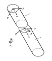
- Figure 1 depicts a two-element complex structure comprising two uniformly birefringent fibre elements 1 and 2 having principal axes x 1,2 and y 1,2 perpendicular to the fibre axis z, and for which x 2 is inclined at an angle 0 to X1 , where 0 is neither zero nor an integral multiple of ⁇ /2.
- the two fibres 1 and 2 of Figure 1 may be connected optically in series by any convenient means, such as a fibre connector, or preferably by a fusion splice.
- Figure 1 depicts the two birefringent elements 1 and 2 as being lengths of birefringent fibre, it should be understood that their place can be taken by birefringent bulk optic elements.
- N 2 and N 1 are independent integers and Av is the separation frequency between the two wavelengths considered.
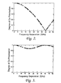
- the vertical axis of Figure 2 represents the degree of co-polarisation of the output axes, and the horizontal axis the frequency difference.
- the degree of co-polarisation is unity when the eigenstates are identical, and is zero when they are orthogonal. It is seen from this graph that an orthogonality relationship occurs in this instance at a frequency separation of 40G Hz.
- Figure 3 is an equivalent graph depicting, in respect of the same complex structure, the corresponding variation in the degree of co-polarisation of the launch eigenstates.
- This figure shows that the launch eigenstates are co-polarised, as required, for a frequency difference of 40GHz.
- ⁇ 1 25ps
- ⁇ 2 12.5ps
- FIG 4 is a dual wavelength transmitter designed for use in a long-haul optically amplified communication system , and that incorporates an SPS as described above with particular reference to Figures 1, 2, and 3.
- One method of providing the two wavelengths is to employ two unmodulated laser sources 40 and 41 separated in frequency by between 5GHz and 100GHz, (e.g. 40GHz).
- a polarisation beam splitter 42 is employed to multiplex the outputs of the two lasers for application with the same polarisation state to an optical modulator 43 used to impress amplitude modulation upon the unmodulated carrier signals provided by the two lasers.
- the polarisation beam splitter may be of the tapered fused fibre type, in which case it may be constructed from polarisation maintaining fibre using the progressive stretching method described in GB 2 150 703 A and GB 2 170 920 A.
- multiple frequencies can be generated from a single laser source in the form of side-bands created in an optical modulator. This can be an additional phase or amplitude modulator, or the same modulator 43 that is used to impart data, but in this instance driven with an additional signal for the purpose of side-band generation.
- the output of the modulator is fed to an SPS 44 via a polarisation state adjuster 45 schematically depicted in Figure 4 as a pair of fibre loops.
- the SPS 44 is the device of Figure 1, and the function of the polarisation adjuster 45 is to convert the polarisation state of the light emerging from the modulator 43 into a polarisation state matching one of the launch eigenstates of the SPS 44.
- this differential delay (transit time difference) between the two wavelength channels amounts to 21.5ps.
- This differential delay is cancelled by feeding the output of the SPS through an equaliser 46.
- This equaliser may comprise a third birefringent (differential delay) element, or alternatively a component showing significant chromatic dispersion can be used.
- a length of dispersive optical fibre which shows a differential group delay equal to 21.5ps could be used as the equaliser element 46.
- the output of the SPS will need to be applied to this third birefringent element with its two appropriate ones of the two principal axes of that third element, thereby implying the need in this instance for a polarisation state adjuster47 to be located between the SPS and this third birefringence element in order to transform the polarisation states of the emerging light form the generally arbitrary emergence eigenstates of the SPS into the required polarisation states for launching into the third element.
- the frequency separation of the two laser should be sufficient to ensure adequate polarisation rotation within one bit period (say at least one complete polarisation evolution). Additionally, small variations in the frequency separation may be expected in practice due to thermal drifts in the transmitter. This implies a frequency separation nominally in excess of 10GHz. The frequency separation of the lasers should be small enough to ensure that they retain the same relative polarisation state as the signal propagates down a long-haul system subject to cable PMD. In general this would imply a frequency separation less than a nominal 100GHz. Additionally, spectral gain variation in the optical amplifiers will limit the maximum tolerable frequency difference. It is believed that the likely optimum separation of the two wavelengths, for a two laser transmitter, will be in the range 30-80GHz.
Landscapes
- Physics & Mathematics (AREA)
- General Physics & Mathematics (AREA)
- Optics & Photonics (AREA)
- Engineering & Computer Science (AREA)
- Signal Processing (AREA)
- Theoretical Computer Science (AREA)
- Optical Communication System (AREA)
Applications Claiming Priority (2)
| Application Number | Priority Date | Filing Date | Title |
|---|---|---|---|
| GB9403740A GB2286937B (en) | 1994-02-26 | 1994-02-26 | Spectral polarisation separator |
| GB9403740 | 1994-02-26 |
Publications (3)
| Publication Number | Publication Date |
|---|---|
| EP0669543A2 true EP0669543A2 (de) | 1995-08-30 |
| EP0669543A3 EP0669543A3 (de) | 1997-12-29 |
| EP0669543B1 EP0669543B1 (de) | 2001-03-14 |
Family
ID=10750988
Family Applications (1)
| Application Number | Title | Priority Date | Filing Date |
|---|---|---|---|
| EP95300143A Expired - Lifetime EP0669543B1 (de) | 1994-02-26 | 1995-01-11 | Spezieller Polarisationsseparator |
Country Status (4)
| Country | Link |
|---|---|
| US (1) | US5576883A (de) |
| EP (1) | EP0669543B1 (de) |
| DE (1) | DE69520298T2 (de) |
| GB (1) | GB2286937B (de) |
Families Citing this family (3)
| Publication number | Priority date | Publication date | Assignee | Title |
|---|---|---|---|---|
| US6476953B1 (en) | 1999-08-18 | 2002-11-05 | Fujitsu Network Communications, Inc. | Wavelength preserving regenerator for DWDM transmission systems |
| WO2023119673A1 (ja) * | 2021-12-24 | 2023-06-29 | 学校法人明治大学 | 評価装置、光受信器、光通信システム、プログラム及び評価方法 |
| CN119522545B (zh) | 2023-06-22 | 2026-01-13 | 学校法人明治大学 | 控制装置、补偿装置、程序以及控制方法 |
Family Cites Families (13)
| Publication number | Priority date | Publication date | Assignee | Title |
|---|---|---|---|---|
| US4495411A (en) * | 1982-10-27 | 1985-01-22 | The United States Of America As Represented By The Secretary Of The Navy | Fiber optic sensors operating at DC |
| US4685773A (en) * | 1984-09-13 | 1987-08-11 | Gte Laboratories Incorporated | Birefringent optical multiplexer with flattened bandpass |
| US4745591A (en) * | 1987-02-24 | 1988-05-17 | Gte Laboratories Incorporated | Multiple channel wavelength division multiplexer/demultiplexer |
| US4744075A (en) * | 1987-04-02 | 1988-05-10 | Gte Laboratories Incorporated | Multichannel wavelength multiplexer/demultiplexer |
| US4981342A (en) * | 1987-09-24 | 1991-01-01 | Allergan Inc. | Multifocal birefringent lens system |
| GB8808043D0 (en) * | 1988-04-06 | 1988-05-25 | British Telecomm | Methods & apparatus for transmitting information |
| DK153791A (da) * | 1991-09-02 | 1993-03-03 | Nkt Res Center As | Fremgangsmaade til undertrykkelse af rin i kohaerente optiske systemer, saasom kommunikationsmodtagere |
| JP2757093B2 (ja) * | 1992-04-20 | 1998-05-25 | 富士電気化学株式会社 | 無偏波分散型光アイソレータ |
| US5298047A (en) * | 1992-08-03 | 1994-03-29 | At&T Bell Laboratories | Method of making a fiber having low polarization mode dispersion due to a permanent spin |
| US5355381A (en) * | 1992-12-03 | 1994-10-11 | Amoco Corporation | Self-heterodyne optical fiber communications system |
| US5351124A (en) * | 1992-12-29 | 1994-09-27 | Honeywell Inc. | Birefringent component axis alignment detector |
| US5327511A (en) * | 1993-06-18 | 1994-07-05 | At&T Bell Laboratories | Apparatus and method employing fast polarization modulation to reduce effects of polarization hole burning and polarization dependent loss |
| JP2739813B2 (ja) * | 1993-12-20 | 1998-04-15 | 日本電気株式会社 | 偏波分散補償方法 |
-
1994
- 1994-02-26 GB GB9403740A patent/GB2286937B/en not_active Expired - Fee Related
-
1995
- 1995-01-11 DE DE69520298T patent/DE69520298T2/de not_active Expired - Fee Related
- 1995-01-11 EP EP95300143A patent/EP0669543B1/de not_active Expired - Lifetime
- 1995-01-13 US US08/372,150 patent/US5576883A/en not_active Expired - Lifetime
Also Published As
| Publication number | Publication date |
|---|---|
| GB2286937B (en) | 1998-06-10 |
| EP0669543B1 (de) | 2001-03-14 |
| GB9403740D0 (en) | 1994-04-13 |
| US5576883A (en) | 1996-11-19 |
| EP0669543A3 (de) | 1997-12-29 |
| DE69520298D1 (de) | 2001-04-19 |
| DE69520298T2 (de) | 2001-07-12 |
| GB2286937A (en) | 1995-08-30 |
Similar Documents
| Publication | Publication Date | Title |
|---|---|---|
| Ryf et al. | 32-bit/s/Hz spectral efficiency WDM transmission over 177-km few-mode fiber | |
| Ryf et al. | Mode-equalized distributed Raman amplification in 137-km few-mode fiber | |
| Ryf et al. | 12× 12 MIMO transmission over 130-km few-mode fiber | |
| US8320769B2 (en) | Transverse-mode multiplexing for optical communication systems | |
| US5737110A (en) | Optical communication system using dark soliton lightwave | |
| Ryf et al. | Mode-multiplexed transmission over a 209-km DGD-compensated hybrid few-mode fiber span | |
| Kwok et al. | Polarization-insensitive all-optical NRZ-to-RZ format conversion by spectral filtering of a cross phase modulation broadened signal spectrum | |
| US5966228A (en) | Optical transmission system and optical repeater | |
| JP2002541720A (ja) | 光学的通信システムにおける偏光モード分散を補償する装置および方法 | |
| Zhu et al. | First demonstration of orbital angular momentum (OAM) distributed Raman amplifier over 18-km OAM fiber with data-carrying OAM multiplexing and wavelength-division multiplexing | |
| Gnauck et al. | Optical equalization of fiber chromatic dispersion in a 5-Gbit/s transmission system | |
| Ryf et al. | 209-km single-span mode-and wavelength-multiplexed transmission over hybrid few-mode fiber | |
| Bergman et al. | An all-optical long-distance multi-Gbytes/s bit-parallel WDM single-fiber link | |
| US7171082B2 (en) | Method and apparatus for optical top-hat pulse generation | |
| EP1566002B1 (de) | Optisches kommunikationssystem | |
| Panda et al. | Performance comparison of dispersion compensation in a pre, post and symmetrical arrangement using DCF for long haul optical communication | |
| Mishra et al. | Investigation of a 16 channel 40 Gbps varied GVD DWDM system using dispersion compensating fiber | |
| EP0669543B1 (de) | Spezieller Polarisationsseparator | |
| US6411413B1 (en) | Method and apparatus for performing dispersion compensation without a change in polarization and a transmitter incorporating same | |
| US20040047633A1 (en) | System and method for high bit-rate optical time division multiplexing (OTDM) | |
| JP4068591B2 (ja) | 光ファイバ伝送システム用の多次数pmd補償器 | |
| US5903384A (en) | Wavelength converter suitable for high bit rates | |
| Lou et al. | 80 Gb/s to 10 Gb/s polarization-insensitive demultiplexing with circularly polarized spun fiber in a two-wavelength nonlinear optical loop mirror | |
| Segatto et al. | Multi Gbit/s bit parallel WDM transmission using dispersion managed fibers | |
| Bae et al. | Practical multiplexing techniques for next-generation data center network |
Legal Events
| Date | Code | Title | Description |
|---|---|---|---|
| PUAI | Public reference made under article 153(3) epc to a published international application that has entered the european phase |
Free format text: ORIGINAL CODE: 0009012 |
|
| AK | Designated contracting states |
Kind code of ref document: A2 Designated state(s): DE FR |
|
| PUAL | Search report despatched |
Free format text: ORIGINAL CODE: 0009013 |
|
| AK | Designated contracting states |
Kind code of ref document: A3 Designated state(s): DE FR |
|
| 17P | Request for examination filed |
Effective date: 19971227 |
|
| RAP3 | Party data changed (applicant data changed or rights of an application transferred) |
Owner name: NORTEL NETWORKS CORPORATION |
|
| 17Q | First examination report despatched |
Effective date: 19990629 |
|
| GRAG | Despatch of communication of intention to grant |
Free format text: ORIGINAL CODE: EPIDOS AGRA |
|
| GRAG | Despatch of communication of intention to grant |
Free format text: ORIGINAL CODE: EPIDOS AGRA |
|
| GRAH | Despatch of communication of intention to grant a patent |
Free format text: ORIGINAL CODE: EPIDOS IGRA |
|
| GRAH | Despatch of communication of intention to grant a patent |
Free format text: ORIGINAL CODE: EPIDOS IGRA |
|
| RAP1 | Party data changed (applicant data changed or rights of an application transferred) |
Owner name: NORTEL NETWORKS LIMITED |
|
| GRAA | (expected) grant |
Free format text: ORIGINAL CODE: 0009210 |
|
| AK | Designated contracting states |
Kind code of ref document: B1 Designated state(s): DE FR |
|
| ET | Fr: translation filed | ||
| REF | Corresponds to: |
Ref document number: 69520298 Country of ref document: DE Date of ref document: 20010419 |
|
| PLBE | No opposition filed within time limit |
Free format text: ORIGINAL CODE: 0009261 |
|
| STAA | Information on the status of an ep patent application or granted ep patent |
Free format text: STATUS: NO OPPOSITION FILED WITHIN TIME LIMIT |
|
| 26N | No opposition filed | ||
| PGFP | Annual fee paid to national office [announced via postgrant information from national office to epo] |
Ref country code: FR Payment date: 20040102 Year of fee payment: 10 |
|
| PGFP | Annual fee paid to national office [announced via postgrant information from national office to epo] |
Ref country code: DE Payment date: 20040130 Year of fee payment: 10 |
|
| PG25 | Lapsed in a contracting state [announced via postgrant information from national office to epo] |
Ref country code: DE Free format text: LAPSE BECAUSE OF NON-PAYMENT OF DUE FEES Effective date: 20050802 |
|
| PG25 | Lapsed in a contracting state [announced via postgrant information from national office to epo] |
Ref country code: FR Free format text: LAPSE BECAUSE OF NON-PAYMENT OF DUE FEES Effective date: 20050930 |
|
| REG | Reference to a national code |
Ref country code: FR Ref legal event code: ST |