EP0669595A2 - Digitalisiertablett und Stift - Google Patents
Digitalisiertablett und Stift Download PDFInfo
- Publication number
- EP0669595A2 EP0669595A2 EP95301124A EP95301124A EP0669595A2 EP 0669595 A2 EP0669595 A2 EP 0669595A2 EP 95301124 A EP95301124 A EP 95301124A EP 95301124 A EP95301124 A EP 95301124A EP 0669595 A2 EP0669595 A2 EP 0669595A2
- Authority
- EP
- European Patent Office
- Prior art keywords
- stylus
- signal
- frequency
- telemetry
- filter
- Prior art date
- Legal status (The legal status is an assumption and is not a legal conclusion. Google has not performed a legal analysis and makes no representation as to the accuracy of the status listed.)
- Granted
Links
Images






Classifications
-
- G—PHYSICS
- G06—COMPUTING OR CALCULATING; COUNTING
- G06F—ELECTRIC DIGITAL DATA PROCESSING
- G06F3/00—Input arrangements for transferring data to be processed into a form capable of being handled by the computer; Output arrangements for transferring data from processing unit to output unit, e.g. interface arrangements
- G06F3/01—Input arrangements or combined input and output arrangements for interaction between user and computer
- G06F3/03—Arrangements for converting the position or the displacement of a member into a coded form
- G06F3/033—Pointing devices displaced or positioned by the user, e.g. mice, trackballs, pens or joysticks; Accessories therefor
- G06F3/038—Control and interface arrangements therefor, e.g. drivers or device-embedded control circuitry
- G06F3/0383—Signal control means within the pointing device
-
- G—PHYSICS
- G06—COMPUTING OR CALCULATING; COUNTING
- G06F—ELECTRIC DIGITAL DATA PROCESSING
- G06F3/00—Input arrangements for transferring data to be processed into a form capable of being handled by the computer; Output arrangements for transferring data from processing unit to output unit, e.g. interface arrangements
- G06F3/01—Input arrangements or combined input and output arrangements for interaction between user and computer
- G06F3/03—Arrangements for converting the position or the displacement of a member into a coded form
- G06F3/033—Pointing devices displaced or positioned by the user, e.g. mice, trackballs, pens or joysticks; Accessories therefor
- G06F3/0354—Pointing devices displaced or positioned by the user, e.g. mice, trackballs, pens or joysticks; Accessories therefor with detection of two-dimensional [2D] relative movements between the device, or an operating part thereof, and a plane or surface, e.g. 2D mice, trackballs, pens or pucks
- G06F3/03545—Pens or stylus
Definitions
- the present invention relates to improvements in digitizer and stylus apparatus.
- the invention concerns telemetry between a stylus and a digitizer tablet, wherein the stylus can deliver status reports about its condition to the tablet.
- the telemetry periods must be correspondingly shortened. For example, if handwriting, which is written by the stylus on the digitizing tablet, is to be recognized by the computer, then the stylus position must be monitored for a relatively long time, thereby reducing the time intervals available for telemetry.
- Reduction of the telemetry time intervals means that a higher data rate in each interval must be used, in order to transmit a required amount of data.
- a higher data rate is generally not feasible because the signal of the stylus is limited to a specific bandwidth. The bandwidth determines the maximum data rate.
- the bandwidth limit imposes a lower limit on the settling time of the signal.
- the limit on settling time in effect, extends the duration of each pulse.
- the increased duration of each individual pulse decreases the total number of pulses which can be transmitted in a given time interval.
- the present invention seeks to provide stylus and digitizer tablet having advantages over such known apparatus.
- a digitizer tablet stylus for producing a stylus position determining signal and a data signal characterized in that said stylus includes first signal producing means for producing said stylus position determining signal and second signal producing means for producing said data signal, said first and second signal producing means being arranged such that a data signal can be delivered from the stylus at the same time as a stylus position determining signal.
- the present invention does not therefore suffer the disadvantages found in the prior art.
- the present invention can provide for a stylus for use with a digitizer tablet and which comprises first oscillator means for producing a position signal and second oscillator means for producing a telemetry carrier signal.
- the present invention can provide for a stylus for use with a digitizer tablet which comprises an oscillator and means for producing a first signal based on said oscillator and means for producing a second signal also based on said oscillator.
- the present invention can provide for a stylus for use with a digitizer tablet comprising two oscillators arranged to run at different frequencies.
- the invention also advantageously provides for a digitizer tablet with first filter means having a pass band centred at a frequency F1, and zeros at other frequencies, and second filter means having a pass band centred at a second frequency F2 which coincides with a zero of said first filter means.
- the present invention can also provide for a digitizer tablet having first filter means which effectively blocks a signal of a first frequency band produced by a stylus, and second filter means which passes said first frequency band.
- the invention can comprise a digitizer tablet for use with a stylus arranged to produce two signals at two different frequencies, and comprising receiver means for receiving one of the signals, the receiver means comprising a rectifier for rectifying the received signal, integrator means for periodically integrating the received signal, and phase-locked-loop means for synchronising the period of integration with one of these signals.
- the invention also comprises a digitizer tablet for use with a stylus arranged to produce two signals, comprising filter means for tracking one of the signals, for maintaining a pass band centred on the tracked signal, and for maintaining a zero centred on the other signal.
- the invention can also provide for a method of operating a stylus associated with a digitizer tablet characterized by the steps of ascertaining the stylus position and simultaneously receiving telemetry data at the tablet from the stylus.
- the present invention can comprise a method of operating a stylus associated with a digitizer tablet, characterized by the steps of using a first carrier and transmitting telemetry data alternately with a position signal, and using a second carrier for transmitting telemetry data exclusively.
- the present invention is particularly advantageous in that it can provide for a stylus for use with a digitizer tablet, which has a channel dedicated exclusively to data signal generation such as in telemetry.
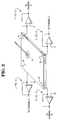
- Fig. 1 is a highly simplified view of a digitizer tablet 3 and its associated stylus 6.
- the digitizer tablet 3 can take the form of a transparent overlay on the display of a portable computer (not shown): the tablet-and-stylus combination then provides input to the computer.
- I-to-V current-to-voltage amplifiers
- the I-to-V amplifiers each produce a voltage (V) indicative of the size of its respective current (I).
- Processing circuitry receives the voltage signals, and computes the position of the stylus signal 6.
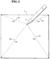
- the currents I1 - I4 are induced because the stylus 6 acts as one plate of a capacitor.
- the digitizer tablet (which bears a resistive surface, or grid, of a material such as indium tin oxide) acts as the other plate.
- Fig. 3 indicates, when negative charge is applied to the tip 2 of the stylus 6, a positive charge is induced on the surface of the tablet 6.
- Currents I1 - I4 supply this positive charge.
- each current can be viewed as following a direct path from the stylus to one corner of the tablet.
- the resistance of each path depends on the length of the path.
- the size of the current depends on the resistance.
- the resistance of each path depends on its length, so that the relative resistances are in proportion to the relative path lengths, as indicated in the Table.
- the current flowing equals the voltage divided by the resistance, V/R, so that the relative currents will be inversely proportional to the relative path lengths, as indicated in the Table.
- the I-to-V amplifiers in Fig. 1 each produce a voltage which is proportional to its respective current.
- the outputs of the I-to-V amplifiers have the relative magnitudes indicated in the Table.
- the output signals can be used to compute the position of the stylus, as stated above.
- a stylus often has the requirement to pass data signals to the tablet in addition to supplying a position detection signal such as signal 9 in Fig. 2.
- the stylus can contain circuitry which monitors battery charge, and other characteristics, and informs the computer, via the digitizing tablet, of these characteristics.
- the information is transferred by modulating the signal produced by the stylus (indicated as "9" in Fig. 2).
- the signal becomes a modulated carrier, and the information transfer comprises telemetry.
- the telemetry periods must be correspondingly shortened. For example, if handwriting, which is written by the stylus on the digitizing tablet, is to be recognized by the computer, then the stylus position must be monitored for a relatively long time, thereby reducing the time intervals available for telemetry.
- Reduction of the telemetry time intervals means that a higher data rate in each interval must be used, in order to transmit a required amount of data.
- a higher data rate is generally not feasible because the signal of the stylus is limited to a specific bandwidth. The bandwidth determines the maximum data rate.
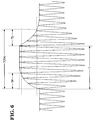
- the bandwidth limit imposes a lower limit on the settling time of the signal, which is illustrated as TS in Fig. 6.
- the limit on settling time in effect, extends the duration of each pulse, from the ideal of T in Fig. 6, to the TOTAL duration indicated.
- the increased duration of each individual pulse decreases the total number of pulses which can be transmitted in a given time interval.
- Fig. 7 illustrates a stylus 6 according to an embodiment of the present invention containing two oscillators, which generate two signals of two different frequencies F1 and F2.
- the signals are delivered to the stylus TIP by conductors 7.
- one frequency, F1 is for example 125 KHz, and is used as the position signal 9 in Fig. 2.
- the other frequency is used for data transfer, for example telemetry, and runs at a specific multiple of F1, such as at 250 KHz, 500 KHz, or 750 KHz.
- a frequency of 250 KHz will be assumed at present for the description of the illustrated embodiments.
- Fig. 8 shows the stylus 6, together with a digitizer tablet 3 according to an embodiment of the present invention and which can take the form of a transparent overlay upon the display of a portable computer.
- the use of tablets with computers is known in the art.
- the stylus transmits the two signals of frequencies F1 and F2. (The two frequencies may be simultaneously transmitted, if telemetry and position are to be undertaken at the same time, but simultaneous transmission at all times may not always be required.)
- the tablet contains one or more receivers which receive the two signals which can effectively comprise carrier signals and feeds them to the FILTERs indicated in the Fig. 8.
- FILTER 1 has the transfer characteristic shown, which is centred about a frequency of 125 KHz.
- Each FILTER 1 passes the 125 KHz position signal to a respective I-to-V amplifier, which produces a signal which is fed to an analysis system (not shown).
- the analysis system computes the stylus position.
- Each FILTER 1 blocks the telemetry carrier.
- the telemetry carrier can be passed by FILTER 2, which is centred about one of the zeros of FILTER 1, as indicated. The zeros are more clearly indicated in Fig. 9.
- FILTER 2 is centred about 250 KHz.
- FILTER 2 passes the telemetry signal of 250 KHz produced by the stylus, but blocks the 125 KHz position signal.
- a position signal and a telemetry signal are transmitted simultaneously to the digitizer tablet 3 by the stylus 6.
- Circuitry internal to the tablet processes the position signal, and ascertains stylus position.
- Other circuitry processes the telemetry signal, which is actually a modulated carrier, and obtains information transmitted by the stylus.
- data also can be carried by the position signal (125 KHz in the example above). That is, the position signal can be arranged to alternate between providing position information and carrying data, as discussed with reference to the prior art.
- a data signal 250 KHz in the example above
- the two signals can carry telemetry data, i.e. the 125 KHz position signal, when not transmitting position information, and the 250 KHz data signal when desired.
- the telemetry signal need not be centred at the particular zero shown in Fig. 8, but can be located at any of them, such as F/4, F/3, F/2, 2F, 3F, or 4F, as shown in Fig. 9.
- Some zeros are located at integral multiples of the position signal, such as 2 x 125 KHz, 3 x 125 KHz, 4 x 125 KHz, and so on.
- Others are located at integral fractional multiples, such as 1/2 x 125 KHz, 1/3 x 125 KHz, 1/4 x 125 KHz, or, more generally, 1/n x (125 KHz), and so on.
- the filters shown in the examples have mutual, blocking zeros. That is, in Fig. 9, zero Z10 of the telemetry-passing filter (FILTER 2) blocks the position signal, while zero 29 of the position-passing filter (FILTER 1) blocks the telemetry signal.
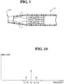
- modulation of the telemetry carrier increases its bandwidth. That is, as a simple example, if a carrier of frequency Fc in Fig. 10 is modulated by a tone of frequency Ft, then the resulting signal spectrum is that shown. The resulting spectrum has a carrier C and two sidebands, one at Fc + Ft and the other at Fc - Ft. This roughly indicates how the bandwidth increases when the telemetry carrier, generated by the stylus, is modulated.
- the frequency spectrum occupied by the telemetry signal will be the simple, discrete triplet shown in Fig. 9.
- a telemetry data rate of 3900 bits per second can be attained, but, in practice, to conserve power in the battery-powered stylus, a data rate of about 500 bits per second is preferred.
- the invention is not limited to the filters having the particular transfer characteristics described above.
- One inventive concept is to filter the telemetry carrier from the position signal particularly if one of the data signal and position signal delivered at the same time from the stylus is modulated by the other. To do this, suitable combinations of bandpass, or notch filters, can be used.
- one bandpass filter centred at the position signal frequency, can pick off the position carrier, and block the telemetry signal.
- a notch filter can be added to either or both for additional suppression of the signal to be blocked, as indicated.
- the invention can provide the benefit of a filter having zeros which track the frequency of the oscillator, as discussed in the following section.
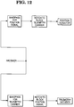
- the invention can advantageously utilize a synchronous coherent detector.
- a synchronous coherent detector One example is shown in Fig. 13. This type of detector exploits the fact that a sine wave integrates to zero, when integrated over an integral number of periods. Fig. 14 illustrates this zero result.
- Fig. 14B illustrates a triangular wave.
- the area of the upper peak cancels the area of the lower peak. The sum is zero, as indicated.
- a high-frequency sine wave 50 (representing the telemetry signal) is added to a low-frequency sine wave 55 (representing the position signal).
- the resulting signal 60 is a modulated sine wave.
- This modulated sine wave is the composite signal broadcast by the stylus and so comprises the telemetry signal and position signal that can be delivered at the same time from the staus 6.
- the illustrated embodiment of the invention rectifies the stylus signal 60, producing the rectified signal 65.
- the illustrated embodiment of the invention then integrates the rectified signal 65, in order to produce a standing voltage which can be converted to a digital word, by an analog-to-digital conversion, or A/D.
- the integration is not done continuously, but periodically, and for time periods equal to the period of the rectified signal 65. That is, the INTEGRATING A/D is clocked at a rate equal to the frequency of the signal 65. For example, as to signal 65, one integration cycle begins at point 70, and ends at point 75.
- this clock rate is an integral fractional multiple of the telemetry frequency (signal 50), and because the telemetry signal is not rectified, the telemetry signal integrates to zero over each integrating period. However, because the position signal has been rectified, and undergoes no negative swings, it does not integrate to zero, but to some positive voltage, which is processed by the A/D circuitry (not explicitly shown).
- the clocking frequency is derived from the received signal 60.
- Phase-locked-loop (PLL) circuitry known in the art, detects the incoming signal 60, and produces a pulse train of identical frequency. This pulse train is used to clock the INTEGRATING A/D.
- a major advantage of using this type of filter is that the PLL tracks the frequency of signal 60 (and thus of signal 55), and maintains the centre of the transfer function at this frequency, which is the POSITION FREQUENCY shown in Fig. 9, even if the POSITION FREQUENCY drifts.
- This system in Fig. 13, suppresses the telemetry signal, and extracts the position signal.
- a second, similar, system can be advantageously employed to suppress the position signal and extract the telemetry signal.
- the position signal 9 in Fig. 2 is functionally different from the data or telemetry signal, at least in the following respect.
- the stylus transmits the same position signal, no matter where the stylus is located. Restated, at the very instant when the stylus signal leaves the stylus, there is no position information contained in it.
- Position information is derived from the currents induced by the signal, as discussed above.
- telemetry information is, in fact, contained in the telemetry signal at the instant when it leaves the stylus.
- the stylus is not transmitting position information.
- the invention can provide for stylus, and associated digitizer tablet apparatus, having a synchronous telemetry channel.
Landscapes
- Engineering & Computer Science (AREA)
- General Engineering & Computer Science (AREA)
- Theoretical Computer Science (AREA)
- Human Computer Interaction (AREA)
- Physics & Mathematics (AREA)
- General Physics & Mathematics (AREA)
- Position Input By Displaying (AREA)
- User Interface Of Digital Computer (AREA)
Applications Claiming Priority (2)
| Application Number | Priority Date | Filing Date | Title |
|---|---|---|---|
| US200721 | 1994-02-23 | ||
| US08/200,721 US5608390A (en) | 1994-02-23 | 1994-02-23 | Synchronous telemetry channel |
Publications (3)
| Publication Number | Publication Date |
|---|---|
| EP0669595A2 true EP0669595A2 (de) | 1995-08-30 |
| EP0669595A3 EP0669595A3 (de) | 1996-08-21 |
| EP0669595B1 EP0669595B1 (de) | 2001-01-31 |
Family
ID=22742911
Family Applications (1)
| Application Number | Title | Priority Date | Filing Date |
|---|---|---|---|
| EP95301124A Expired - Lifetime EP0669595B1 (de) | 1994-02-23 | 1995-02-22 | Digitalisiertablett und Stift |
Country Status (4)
| Country | Link |
|---|---|
| US (1) | US5608390A (de) |
| EP (1) | EP0669595B1 (de) |
| JP (1) | JPH0836451A (de) |
| DE (1) | DE69520010T2 (de) |
Cited By (1)
| Publication number | Priority date | Publication date | Assignee | Title |
|---|---|---|---|---|
| CN100373309C (zh) * | 1998-06-26 | 2008-03-05 | 株式会社华科姆 | 数字转换器图形输入板系统 |
Families Citing this family (29)
| Publication number | Priority date | Publication date | Assignee | Title |
|---|---|---|---|---|
| US7064749B1 (en) * | 1992-11-09 | 2006-06-20 | Adc Technology Inc. | Portable communicator |
| EP1130536B1 (de) * | 1994-12-16 | 2004-04-28 | Hyundai Electronics America | Gerät und Verfahren mit Digitalisierstift |
| FI103837B (fi) * | 1994-12-22 | 1999-09-30 | Nokia Mobile Phones Ltd | Tiedonsiirto- ja käsittelymenetelmä |
| US6441810B1 (en) * | 1995-10-31 | 2002-08-27 | Lsi Logic Corporation | Telemetry encoding technique for smart stylus |
| US20040083174A1 (en) | 2000-06-30 | 2004-04-29 | Kia Silverbrook | Method and system for banking using coded forms |
| AU2002364108A1 (en) * | 2001-12-26 | 2003-07-24 | Firooz Ghassabian | Stylus computer and method of manipulating data |
| US6802229B1 (en) | 2003-06-02 | 2004-10-12 | Michael Lambert | Gear drive having continuously variable drive ratio |
| US9201556B2 (en) * | 2006-11-08 | 2015-12-01 | 3M Innovative Properties Company | Touch location sensing system and method employing sensor data fitting to a predefined curve |
| US8207944B2 (en) * | 2006-12-19 | 2012-06-26 | 3M Innovative Properties Company | Capacitance measuring circuit and method |
| US8134542B2 (en) * | 2006-12-20 | 2012-03-13 | 3M Innovative Properties Company | Untethered stylus employing separate communication and power channels |
| US8243049B2 (en) * | 2006-12-20 | 2012-08-14 | 3M Innovative Properties Company | Untethered stylus employing low current power converter |
| US8040329B2 (en) * | 2006-12-20 | 2011-10-18 | 3M Innovative Properties Company | Frequency control circuit for tuning a resonant circuit of an untethered device |
| US8040330B2 (en) * | 2006-12-28 | 2011-10-18 | 3M Innovative Properties Company | Untethered stylus empolying multiple reference frequency communication |
| US8089474B2 (en) * | 2006-12-28 | 2012-01-03 | 3M Innovative Properties Company | Location sensing system and method employing adaptive drive signal adjustment |
| TW201039113A (en) * | 2009-04-29 | 2010-11-01 | Prime View Int Co Ltd | Digital electronic apparatus |
| JP5345050B2 (ja) * | 2009-12-25 | 2013-11-20 | 株式会社ワコム | 指示体、位置検出装置及び位置検出方法 |
| US9310923B2 (en) | 2010-12-03 | 2016-04-12 | Apple Inc. | Input device for touch sensitive devices |
| US8928635B2 (en) | 2011-06-22 | 2015-01-06 | Apple Inc. | Active stylus |
| US9329703B2 (en) | 2011-06-22 | 2016-05-03 | Apple Inc. | Intelligent stylus |
| US9557845B2 (en) * | 2012-07-27 | 2017-01-31 | Apple Inc. | Input device for and method of communication with capacitive devices through frequency variation |
| US9652090B2 (en) * | 2012-07-27 | 2017-05-16 | Apple Inc. | Device for digital communication through capacitive coupling |
| US20140038524A1 (en) * | 2012-07-31 | 2014-02-06 | Research In Motion Limited | Method and apparatus pertaining to the timing of stylus location transmissions |
| US10048775B2 (en) | 2013-03-14 | 2018-08-14 | Apple Inc. | Stylus detection and demodulation |
| US9939935B2 (en) | 2013-07-31 | 2018-04-10 | Apple Inc. | Scan engine for touch controller architecture |
| RU2595721C2 (ru) | 2014-11-06 | 2016-08-27 | Максим Владимирович Савинов | Трансмиссия на шестернях со спиральными зубчатыми переходами |
| US10061450B2 (en) | 2014-12-04 | 2018-08-28 | Apple Inc. | Coarse scan and targeted active mode scan for touch |
| US10474277B2 (en) | 2016-05-31 | 2019-11-12 | Apple Inc. | Position-based stylus communication |
| KR102738420B1 (ko) * | 2019-09-20 | 2024-12-04 | 주식회사 하이딥 | 스타일러스 펜, 터치 장치, 및 터치 시스템 |
| US12153764B1 (en) | 2020-09-25 | 2024-11-26 | Apple Inc. | Stylus with receive architecture for position determination |
Family Cites Families (18)
| Publication number | Priority date | Publication date | Assignee | Title |
|---|---|---|---|---|
| US3952302A (en) * | 1965-06-21 | 1976-04-20 | Hughes Aircraft Company | Synchronous detector with pulse repetition frequency modulation |
| US3629716A (en) * | 1969-03-24 | 1971-12-21 | Infinite Q Corp | Method and apparatus of infinite q detection |
| US3745255A (en) * | 1971-08-18 | 1973-07-10 | J Fletcher | Receiver with an improved phase lock loop in a multichannel telemetry system with suppressed carrier |
| US4209750A (en) * | 1978-06-19 | 1980-06-24 | The Foxboro Company | Swept-carrier transmission system adapted for use in process control systems |
| US4337660A (en) * | 1979-08-29 | 1982-07-06 | Amf Incorporated | Ultrasonic tire testing apparatus |
| US4310805A (en) * | 1979-12-13 | 1982-01-12 | General Electric Company | Phase-locked loop stabilized by a crystal oscillator |
| DE3789922T2 (de) * | 1986-07-23 | 1995-01-05 | Wacom Co Ltd | Koordinateneingabesystem. |
| JPH07107661B2 (ja) * | 1986-09-08 | 1995-11-15 | 株式会社ワコム | 位置指示器の状態検出方式 |
| US4733404A (en) * | 1986-11-25 | 1988-03-22 | Hewlett-Packard Company | Apparatus and method for signal processing |
| US4883926A (en) * | 1988-04-21 | 1989-11-28 | Hewlett-Packard Company | Stylus switch |
| ES2068228T3 (es) * | 1988-11-11 | 1995-04-16 | Canon Kk | Aparato para la introduccion de coordenadas. |
| US5140699A (en) * | 1990-12-24 | 1992-08-18 | American Nucleonics Corporation | Detector DC offset compensator |
| US5138118A (en) * | 1991-05-06 | 1992-08-11 | International Business Machines Corporation | Pulsed pen for use with a digitizer tablet |
| JPH0792722B2 (ja) * | 1992-02-21 | 1995-10-09 | グラフテック株式会社 | デジタイザ |
| US5369227A (en) * | 1992-07-22 | 1994-11-29 | Summagraphics Corporation | Stylus switch status determination in a digitizer tablet having a cordless stylus |
| US5459432A (en) * | 1993-07-22 | 1995-10-17 | Rockwell International Corporation | Use of a chopper and a sigma-delta modulator for downconverting and digitizing an analog signal including information modulated by a carrier |
| US5446416A (en) * | 1993-10-20 | 1995-08-29 | Industrial Technology Research Institute | Time acquisition system with dual-loop for independent frequency phase lock |
| US5373118A (en) * | 1993-10-25 | 1994-12-13 | Calcomp Inc. | Half normal frequency regime phase encoding in cordless digitizers |
-
1994
- 1994-02-23 US US08/200,721 patent/US5608390A/en not_active Expired - Lifetime
-
1995
- 1995-02-22 JP JP3341595A patent/JPH0836451A/ja active Pending
- 1995-02-22 EP EP95301124A patent/EP0669595B1/de not_active Expired - Lifetime
- 1995-02-22 DE DE69520010T patent/DE69520010T2/de not_active Expired - Lifetime
Cited By (1)
| Publication number | Priority date | Publication date | Assignee | Title |
|---|---|---|---|---|
| CN100373309C (zh) * | 1998-06-26 | 2008-03-05 | 株式会社华科姆 | 数字转换器图形输入板系统 |
Also Published As
| Publication number | Publication date |
|---|---|
| EP0669595A3 (de) | 1996-08-21 |
| DE69520010T2 (de) | 2001-05-23 |
| DE69520010D1 (de) | 2001-03-08 |
| US5608390A (en) | 1997-03-04 |
| JPH0836451A (ja) | 1996-02-06 |
| EP0669595B1 (de) | 2001-01-31 |
Similar Documents
| Publication | Publication Date | Title |
|---|---|---|
| EP0669595B1 (de) | Digitalisiertablett und Stift | |
| US8134542B2 (en) | Untethered stylus employing separate communication and power channels | |
| US8159474B2 (en) | Untethered stylus employing multiple reference frequency communication | |
| US8797301B2 (en) | Active stylus to host data transmitting method | |
| US5218174A (en) | Low power cordless magnetic field digitizer with differential grid sensing and synchronous position demodulation | |
| US9658720B2 (en) | Capacitive sense array for detecting passive touch objects and an active stylus | |
| US6777922B2 (en) | Information processing apparatus for inputting a signal, and method therefor | |
| US8265201B1 (en) | Adaptive timing using clock recovery | |
| US20140327644A1 (en) | Papr optimized ofdm touch engine with tone spaced windowed demodulation | |
| US20140035870A1 (en) | Control method and electronic stylus for touch input to a capacitive touchpad module | |
| JPH09106320A (ja) | 図形入力装置および図形入力方法 | |
| NL8401692A (nl) | Het opslaan van gegevens die betrekking hebben op het televisie kijken. | |
| DE69933520D1 (de) | Datenträger mit korrekturmöglichkeiten und verbesserter spannungsbegrenzungsmöglichkeit | |
| EP0783211A3 (de) | Einrichtung zur Fernablesung von Zählern | |
| GB900611A (en) | Improvements in receivers for use in phase-shift signalling systems and in systems incorporating such receivers | |
| FR2635809B1 (fr) | Systeme d'echange d'informations entre un objet portatif comme une cle, et un dispositif d'echange | |
| WO2000016302A8 (en) | Method and apparatus for bidirectional data transfer between a digital display and a computer | |
| US2708268A (en) | Sequential phase-shifted amplitude modulated carrier wave | |
| GB2198014A (en) | Information transfer system | |
| CA2121575A1 (en) | Digitizer tablet with cordless pointing device | |
| CN119356547A (zh) | 触摸控制器、信号获取方法、芯片及电子设备 | |
| JP2517108B2 (ja) | ディジタル送受信装置 | |
| SU995263A1 (ru) | Частотный детектор | |
| SU866754A1 (ru) | Приемник частотно-манипулированных сигналов | |
| GB2323460A (en) | Card reading system |
Legal Events
| Date | Code | Title | Description |
|---|---|---|---|
| PUAI | Public reference made under article 153(3) epc to a published international application that has entered the european phase |
Free format text: ORIGINAL CODE: 0009012 |
|
| AK | Designated contracting states |
Kind code of ref document: A2 Designated state(s): DE FR GB |
|
| PUAL | Search report despatched |
Free format text: ORIGINAL CODE: 0009013 |
|
| AK | Designated contracting states |
Kind code of ref document: A3 Designated state(s): DE FR GB |
|
| 17P | Request for examination filed |
Effective date: 19961017 |
|
| RAP1 | Party data changed (applicant data changed or rights of an application transferred) |
Owner name: SYMBIOS, INC. |
|
| 17Q | First examination report despatched |
Effective date: 19980615 |
|
| RAP1 | Party data changed (applicant data changed or rights of an application transferred) |
Owner name: HYUNDAI ELECTRONICS AMERICA |
|
| RTI1 | Title (correction) |
Free format text: DIGITIZER TABLET AND STYLUS |
|
| GRAG | Despatch of communication of intention to grant |
Free format text: ORIGINAL CODE: EPIDOS AGRA |
|
| GRAG | Despatch of communication of intention to grant |
Free format text: ORIGINAL CODE: EPIDOS AGRA |
|
| GRAH | Despatch of communication of intention to grant a patent |
Free format text: ORIGINAL CODE: EPIDOS IGRA |
|
| RTI1 | Title (correction) |
Free format text: DIGITIZER TABLET AND STYLUS |
|
| GRAH | Despatch of communication of intention to grant a patent |
Free format text: ORIGINAL CODE: EPIDOS IGRA |
|
| GRAA | (expected) grant |
Free format text: ORIGINAL CODE: 0009210 |
|
| AK | Designated contracting states |
Kind code of ref document: B1 Designated state(s): DE FR GB |
|
| REF | Corresponds to: |
Ref document number: 69520010 Country of ref document: DE Date of ref document: 20010308 |
|
| ET | Fr: translation filed | ||
| PLBE | No opposition filed within time limit |
Free format text: ORIGINAL CODE: 0009261 |
|
| STAA | Information on the status of an ep patent application or granted ep patent |
Free format text: STATUS: NO OPPOSITION FILED WITHIN TIME LIMIT |
|
| REG | Reference to a national code |
Ref country code: GB Ref legal event code: IF02 |
|
| 26N | No opposition filed | ||
| REG | Reference to a national code |
Ref country code: GB Ref legal event code: 732E |
|
| REG | Reference to a national code |
Ref country code: FR Ref legal event code: TP |
|
| REG | Reference to a national code |
Ref country code: GB Ref legal event code: 732E |
|
| REG | Reference to a national code |
Ref country code: GB Ref legal event code: 732E |
|
| REG | Reference to a national code |
Ref country code: FR Ref legal event code: TP |
|
| PGFP | Annual fee paid to national office [announced via postgrant information from national office to epo] |
Ref country code: DE Payment date: 20140227 Year of fee payment: 20 |
|
| PGFP | Annual fee paid to national office [announced via postgrant information from national office to epo] |
Ref country code: FR Payment date: 20140220 Year of fee payment: 20 |
|
| PGFP | Annual fee paid to national office [announced via postgrant information from national office to epo] |
Ref country code: GB Payment date: 20140227 Year of fee payment: 20 |
|
| REG | Reference to a national code |
Ref country code: DE Ref legal event code: R071 Ref document number: 69520010 Country of ref document: DE |
|
| REG | Reference to a national code |
Ref country code: GB Ref legal event code: PE20 Expiry date: 20150221 |
|
| PG25 | Lapsed in a contracting state [announced via postgrant information from national office to epo] |
Ref country code: GB Free format text: LAPSE BECAUSE OF EXPIRATION OF PROTECTION Effective date: 20150221 |