EP0669612A2 - Appareil d'enregistrement optique - Google Patents
Appareil d'enregistrement optique Download PDFInfo
- Publication number
- EP0669612A2 EP0669612A2 EP95107275A EP95107275A EP0669612A2 EP 0669612 A2 EP0669612 A2 EP 0669612A2 EP 95107275 A EP95107275 A EP 95107275A EP 95107275 A EP95107275 A EP 95107275A EP 0669612 A2 EP0669612 A2 EP 0669612A2
- Authority
- EP
- European Patent Office
- Prior art keywords
- pulse
- signal
- laser light
- recording
- succeeding
- Prior art date
- Legal status (The legal status is an assumption and is not a legal conclusion. Google has not performed a legal analysis and makes no representation as to the accuracy of the status listed.)
- Granted
Links
Images


Classifications
-
- G—PHYSICS
- G11—INFORMATION STORAGE
- G11B—INFORMATION STORAGE BASED ON RELATIVE MOVEMENT BETWEEN RECORD CARRIER AND TRANSDUCER
- G11B7/00—Recording or reproducing by optical means, e.g. recording using a thermal beam of optical radiation by modifying optical properties or the physical structure, reproducing using an optical beam at lower power by sensing optical properties; Record carriers therefor
- G11B7/12—Heads, e.g. forming of the optical beam spot or modulation of the optical beam
- G11B7/125—Optical beam sources therefor, e.g. laser control circuitry specially adapted for optical storage devices; Modulators, e.g. means for controlling the size or intensity of optical spots or optical traces
- G11B7/126—Circuits, methods or arrangements for laser control or stabilisation
-
- G—PHYSICS
- G11—INFORMATION STORAGE
- G11B—INFORMATION STORAGE BASED ON RELATIVE MOVEMENT BETWEEN RECORD CARRIER AND TRANSDUCER
- G11B11/00—Recording on or reproducing from the same record carrier wherein for these two operations the methods are covered by different main groups of groups G11B3/00 - G11B7/00 or by different subgroups of group G11B9/00; Record carriers therefor
- G11B11/10—Recording on or reproducing from the same record carrier wherein for these two operations the methods are covered by different main groups of groups G11B3/00 - G11B7/00 or by different subgroups of group G11B9/00; Record carriers therefor using recording by magnetic means or other means for magnetisation or demagnetisation of a record carrier, e.g. light induced spin magnetisation; Demagnetisation by thermal or stress means in the presence or not of an orienting magnetic field
- G11B11/105—Recording on or reproducing from the same record carrier wherein for these two operations the methods are covered by different main groups of groups G11B3/00 - G11B7/00 or by different subgroups of group G11B9/00; Record carriers therefor using recording by magnetic means or other means for magnetisation or demagnetisation of a record carrier, e.g. light induced spin magnetisation; Demagnetisation by thermal or stress means in the presence or not of an orienting magnetic field using a beam of light or a magnetic field for recording by change of magnetisation and a beam of light for reproducing, i.e. magneto-optical, e.g. light-induced thermomagnetic recording, spin magnetisation recording, Kerr or Faraday effect reproducing
- G11B11/10502—Recording on or reproducing from the same record carrier wherein for these two operations the methods are covered by different main groups of groups G11B3/00 - G11B7/00 or by different subgroups of group G11B9/00; Record carriers therefor using recording by magnetic means or other means for magnetisation or demagnetisation of a record carrier, e.g. light induced spin magnetisation; Demagnetisation by thermal or stress means in the presence or not of an orienting magnetic field using a beam of light or a magnetic field for recording by change of magnetisation and a beam of light for reproducing, i.e. magneto-optical, e.g. light-induced thermomagnetic recording, spin magnetisation recording, Kerr or Faraday effect reproducing characterised by the transducing operation to be executed
- G11B11/1053—Recording on or reproducing from the same record carrier wherein for these two operations the methods are covered by different main groups of groups G11B3/00 - G11B7/00 or by different subgroups of group G11B9/00; Record carriers therefor using recording by magnetic means or other means for magnetisation or demagnetisation of a record carrier, e.g. light induced spin magnetisation; Demagnetisation by thermal or stress means in the presence or not of an orienting magnetic field using a beam of light or a magnetic field for recording by change of magnetisation and a beam of light for reproducing, i.e. magneto-optical, e.g. light-induced thermomagnetic recording, spin magnetisation recording, Kerr or Faraday effect reproducing characterised by the transducing operation to be executed to compensate for the magnetic domain drift or time shift
-
- G—PHYSICS
- G11—INFORMATION STORAGE
- G11B—INFORMATION STORAGE BASED ON RELATIVE MOVEMENT BETWEEN RECORD CARRIER AND TRANSDUCER
- G11B11/00—Recording on or reproducing from the same record carrier wherein for these two operations the methods are covered by different main groups of groups G11B3/00 - G11B7/00 or by different subgroups of group G11B9/00; Record carriers therefor
- G11B11/10—Recording on or reproducing from the same record carrier wherein for these two operations the methods are covered by different main groups of groups G11B3/00 - G11B7/00 or by different subgroups of group G11B9/00; Record carriers therefor using recording by magnetic means or other means for magnetisation or demagnetisation of a record carrier, e.g. light induced spin magnetisation; Demagnetisation by thermal or stress means in the presence or not of an orienting magnetic field
- G11B11/105—Recording on or reproducing from the same record carrier wherein for these two operations the methods are covered by different main groups of groups G11B3/00 - G11B7/00 or by different subgroups of group G11B9/00; Record carriers therefor using recording by magnetic means or other means for magnetisation or demagnetisation of a record carrier, e.g. light induced spin magnetisation; Demagnetisation by thermal or stress means in the presence or not of an orienting magnetic field using a beam of light or a magnetic field for recording by change of magnetisation and a beam of light for reproducing, i.e. magneto-optical, e.g. light-induced thermomagnetic recording, spin magnetisation recording, Kerr or Faraday effect reproducing
- G11B11/10595—Control of operating function
-
- G—PHYSICS
- G11—INFORMATION STORAGE
- G11B—INFORMATION STORAGE BASED ON RELATIVE MOVEMENT BETWEEN RECORD CARRIER AND TRANSDUCER
- G11B20/00—Signal processing not specific to the method of recording or reproducing; Circuits therefor
- G11B20/10—Digital recording or reproducing
- G11B20/10009—Improvement or modification of read or write signals
- G11B20/10046—Improvement or modification of read or write signals filtering or equalising, e.g. setting the tap weights of an FIR filter
- G11B20/10194—Improvement or modification of read or write signals filtering or equalising, e.g. setting the tap weights of an FIR filter using predistortion during writing
-
- G—PHYSICS
- G11—INFORMATION STORAGE
- G11B—INFORMATION STORAGE BASED ON RELATIVE MOVEMENT BETWEEN RECORD CARRIER AND TRANSDUCER
- G11B7/00—Recording or reproducing by optical means, e.g. recording using a thermal beam of optical radiation by modifying optical properties or the physical structure, reproducing using an optical beam at lower power by sensing optical properties; Record carriers therefor
- G11B7/004—Recording, reproducing or erasing methods; Read, write or erase circuits therefor
- G11B7/0045—Recording
-
- G—PHYSICS
- G11—INFORMATION STORAGE
- G11B—INFORMATION STORAGE BASED ON RELATIVE MOVEMENT BETWEEN RECORD CARRIER AND TRANSDUCER
- G11B11/00—Recording on or reproducing from the same record carrier wherein for these two operations the methods are covered by different main groups of groups G11B3/00 - G11B7/00 or by different subgroups of group G11B9/00; Record carriers therefor
- G11B11/10—Recording on or reproducing from the same record carrier wherein for these two operations the methods are covered by different main groups of groups G11B3/00 - G11B7/00 or by different subgroups of group G11B9/00; Record carriers therefor using recording by magnetic means or other means for magnetisation or demagnetisation of a record carrier, e.g. light induced spin magnetisation; Demagnetisation by thermal or stress means in the presence or not of an orienting magnetic field
- G11B11/105—Recording on or reproducing from the same record carrier wherein for these two operations the methods are covered by different main groups of groups G11B3/00 - G11B7/00 or by different subgroups of group G11B9/00; Record carriers therefor using recording by magnetic means or other means for magnetisation or demagnetisation of a record carrier, e.g. light induced spin magnetisation; Demagnetisation by thermal or stress means in the presence or not of an orienting magnetic field using a beam of light or a magnetic field for recording by change of magnetisation and a beam of light for reproducing, i.e. magneto-optical, e.g. light-induced thermomagnetic recording, spin magnetisation recording, Kerr or Faraday effect reproducing
- G11B11/10502—Recording on or reproducing from the same record carrier wherein for these two operations the methods are covered by different main groups of groups G11B3/00 - G11B7/00 or by different subgroups of group G11B9/00; Record carriers therefor using recording by magnetic means or other means for magnetisation or demagnetisation of a record carrier, e.g. light induced spin magnetisation; Demagnetisation by thermal or stress means in the presence or not of an orienting magnetic field using a beam of light or a magnetic field for recording by change of magnetisation and a beam of light for reproducing, i.e. magneto-optical, e.g. light-induced thermomagnetic recording, spin magnetisation recording, Kerr or Faraday effect reproducing characterised by the transducing operation to be executed
- G11B11/10504—Recording
- G11B11/10506—Recording by modulating only the light beam of the transducer
Definitions
- the present invention relates to an optical recording apparatus capable of performing a high-density recording by removing the influence of remaining heat of a recording medium due to a preceding laser light pulse radiated thereon.
- FIG. 1 An example of the construction of the conventional optical recording apparatus is shown in Fig. 1.
- Fig. 1 An example of the construction of the conventional optical recording apparatus is shown in Fig. 1.
- the explanation of various types of servo control circuits will be omitted in this conventional example of Fig. 1.
- reference numeral 1 denotes a magneto-optical disc acting as an optical disc which is capable of rewriting data and rotated at a constant angular velocity or a constant linear velocity by a spindle motor 2.
- Reference numeral 10 denotes an optical head having a laser diode 11 and a photo diode 12 for writing data to (or reading data from) the magneto-optical disc 1.
- a magnetic head 10a acting as an external magnetic field supplying apparatus is disposed in opposite to the optical head 10 through the magneto-optical disc 1 in a manner that the magnetic head and the optical head sandwich the magneto-optical disc 1 in an opposite manner.
- magnetizing direction of a part of a vertical magnetic recording film of the magneto-optical disc 1 where a laser light beam from the optical head 10 is radiated is changed in accordance with a direction of external magnetic field supplied from the magnetic head 10a.
- Reference numeral 20 denotes a recording circuit system, wherein digital data as an information signal to be recorded on the magneto-optical disc 1 is supplied to an encoder 21 through an input terminal IN and converted not only into a predetermined format but also into a recording signal accorded with a modulation method such as a pulse position modulation, for example, by the encoder 21.
- the output of the encoder 21 is supplied to a light intensity modulation circuit 22 which in turn delivers an output signal to the laser diode 11 through a driving amplifier 23 to thereby intermittently control an intensity of radiated light from the diode.
- a part of the laser light beam radiated from the laser diode 11 is reflected by a prism mirror and detected by the photo diode 12.
- the detected output of the photo diode 12 is supplied to a comparator 25 through an amplifier 24 and compared therein with a reference value applied from a reference value setting circuit 26.
- the output from the comparator 25 is fed back to the light intensity modulation circuit 22 to control the light intensity (power level) of the laser diode 11 at a constant value, thereby performing a so-called automatic power control (APC).
- APC automatic power control
- a temperature of a recording layer of the magneto-optical disc 1 increases and then decreases as shown in Fig. 2B, so that a mark with a length twice as large as the pulse width of the radiated laser beam, that is, a time length of 100 nS is recorded in the recording layer with a Curie point Tc of 180°C, for example, illustration thereof being omitted.
- the temperature of the recording layer corresponds to the center of radiation of the laser light beam whose energy density is accorded with Gausian distribution and is influenced also by thermal diffusion in the recording layer.
- the temperature of the recording layer of the magneto-optical disc 1 has decreased to a value almost same as that before the beam radiation thereon, so that a succeeding mark can be formed without being influenced by the remaining heat generated when forming the preceding mark.
- the modulation method such as the pulse position modulation can be employed without any difficulty.
- JP-A-58-212628 filed by the same applicant as the present application and so on for example, due to the influence by the thermal diffusion of the recording layer, it is required to reduce a pulse width of the radiated laser light beam and to increase a power level thereof when compared with the above-described example.
- a laser light with a pulse width of 15 nS and a power level of 20 mW, for example is radiated from the diode 11 as shown in Fig. 3A to thereby increase and then decrease a temperature of the recording layer of the magneto-optical disc 1 as shown in Fig. 3B to form a mark with a predetermined time length, that is, 50 nS can be formed.
- a time period lapsed after termination of the laser beam radiation is such a shorter value as almost half of that of the above-described example, so that a temperature of the recording layer of the magneto-optical disc 1 merely decreases to a value higher by about 40 ° C than a temperature at the initiation of the laser beam radiation.
- This residual temperature increase that is, remaining heat generated when forming the preceding mark is added to the temperature increase of the recording layer when forming a succeeding mark as shown by a dotted line in Fig. 3B, so that a time period required to reach to Curie point Tc in the recording layer is made shorter in a temperature rising mode and a time period required to reach to Curie point Tc in the recording layer is made longer in a temperature falling mode.
- front and rear edges of a mark to be formed are shifted to a former and a rear side from predetermined positions respectively and so a desired mark can not be formed accurately, whereby there was such a problem that an error occurs in data reproduced from the marks in the modulation method of the pulse position modulation type.
- a known optical recording apparatus controls the laser power.
- the amplitude of the laser driving signal pulse is increased automatically in case of a longer pause time between two pulses, and if the preceding pulse is dense, the amplitude is decreased. Then the result is recorded. Thus the level and the peak shift of the reproduced waveform is considerably decreased.
- JP 59-117743 A Another known optical recording apparatus controls the laser power in response to the changing of the relative speed between a recording head and a recording medium. The influence of remaining heat of the recording medium is not mentioned.
- an object of the present invention to provide an optical recording apparatus which is capable of recording a high-density pulse signal accurately on a recording medium by cancelling influence of remaining heat of the recording medium due to a laser light pulse corresponding to a preceding pulse signal.
- an optical recording apparatus is constructed in a manner that, in an optical recording apparatus wherein a modulation signal based on recording data is supplied to a light intensity modulation circuit 22 for a laser light source 11 and a light beam from the laser beam source thus modulated is radiated on an optical recording medium 1 to record data thereon, pattern detecting means 31 for detecting a pulse pattern of the modulation signal and pulse width control means 36 for controlling a pulse width of the modulation signal are provided, and when the pattern detecting means detects a signal pulse with an interval not more than a predetermined value, a pulse width of a signal pulse succeeding to the pulse is shortened.
- influence of remaining heat of the recording medium due to a laser light pulse corresponding to a preceding signal pulse is cancelled to thereby record a high-density pulse signal accurately on a recording medium.
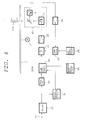
- Fig. 4 The constructions of the embodiment of the present invention is shown in Fig. 4 and the construction of main parts thereof is shown in Fig. 5.
- Fig. 4 constituent elements corresponding to those shown in Figs. 1 to 3 are represented by the same reference numerals and the explanation thereof is omitted.
- reference numeral 20W denotes a recording circuit system having a pulse width control circuit 36 for controlling a pulse width of a recording signal.
- An output of an encoder 21 is supplied to a pattern detecting circuit 31 and also to the pulse width control circuit 36 through a delay circuit 32.
- the pattern detecting circuit 31 detects a pulse pattern of the recording signal.
- the delay circuit 32 is compensating a signal processing time.
- the pulse width control circuit 36 also receives an output from a recording speed setting circuit 34 and delivers an output thereof to a modulation circuit 22 directly.
- a reference value from a reference value setting circuit 26 is supplied to a comparator 25. The rest of the construction is the same as that of the example of Fig. 1.
- reference numeral 60 denotes a pulse width control circuit corresponding to the pulse width control circuit 36 in Fig. 4.
- An input pulse from a terminal IN is supplied to each of a delay circuit 61 and AND gates 62 and 63 and an output of the delay circuit 61 with a delay time of 7 is supplied to the AND gate 62.
- a detection signal from a terminal DT is directly applied to the AND gate 62 and also applied to the AND gate 63 through a NOT circuit 64.
- Output signals from the AND gates 62 and 63 are delivered to a terminal OUT through an OR gate 65.
- the control circuit 36 controls a pulse width of an input pulse applied thereto in accordance with the detecting signal representing this fact from the pattern detecting circuit in a manner that a leading edge of a succeeding laser light pulse is delayed by the time 7 as shown in Fig. 6A.
- a degree of decreasing a pulse width of a succeeding pulse signal relative to an amplitude of a normal pulse signal depends not only on a recording linear velocity and an atmospheric temperature where the recording is performed as a matter of course but also is required to be changed depending on a pulse interval between the preceding and succeeding pulse signals, as in the same manner in case of decreasing a rate of an amplitude of a pulse signal as described above.
- the relation between a pulse interval and a temperature of the recording medium of the magneto-optical disc becomes same as that in case of decreasing an amplitude of a pulse signal as described above.
- the radiation time period of a succeeding laser light pulse on the recording layer is shortened an so the temperature increasing rate of the recording layer of the magneto-optical disc 1 due to a succeeding laser light pulse becomes slightly gentle, so that a temperature of the recording layer at a time point of termination of radiation of the succeeding laser light pulse increases merely to the same level as that at a time point of termination of radiation of a preceding laser light pulse, as shown by a solid line in Fig. 6B, thereby cancelling the influence of the remaining heat of the recording medium due to a preceding laser light pulse to make it possible to record a high-density pulse signal accurately.
- the leading edge of the succeeding laser light pulse is delayed by the time T , but the same effect can be obtained by shortening a pulse width of a laser light beam pulse in a manner of advancing a trailing edge thereof by a suitable time period or by shifting both the leading and trailing edges thereof by a suitable time period.
- the present invention can be applied to any types of optical discs which are capable of recording data thereon.
- the present invention can be applied to a recording apparatus which mounts an optical disc such as a rewriteable type optical disc of a phase change type using a chalcogenide thin film or a write-once type optical disc using tellurium oxide etc. or the like.
- an pulse width of a succeeding pulse signal is shortened to thereby decrease a radiation energy of a laser light pulse, so that there can be provided with an optical recording apparatus which can cancel the influence of the remaining heat of the recording medium due to a preceding laser light pulse to make it possible to record a high-density pulse signal accurately.
Landscapes
- Physics & Mathematics (AREA)
- Optics & Photonics (AREA)
- Engineering & Computer Science (AREA)
- Signal Processing (AREA)
- Optical Recording Or Reproduction (AREA)
- Optical Head (AREA)
Applications Claiming Priority (4)
| Application Number | Priority Date | Filing Date | Title |
|---|---|---|---|
| JP33083889 | 1989-12-20 | ||
| JP330838/89 | 1989-12-20 | ||
| JP33083889 | 1989-12-20 | ||
| EP91900322A EP0458975B1 (fr) | 1989-12-20 | 1990-12-17 | Appareil d'enregistrement optique |
Related Parent Applications (2)
| Application Number | Title | Priority Date | Filing Date |
|---|---|---|---|
| EP91900322A Division EP0458975B1 (fr) | 1989-12-20 | 1990-12-17 | Appareil d'enregistrement optique |
| EP91900322.8 Division | 1990-12-17 |
Publications (3)
| Publication Number | Publication Date |
|---|---|
| EP0669612A2 true EP0669612A2 (fr) | 1995-08-30 |
| EP0669612A3 EP0669612A3 (fr) | 1996-06-26 |
| EP0669612B1 EP0669612B1 (fr) | 2000-03-08 |
Family
ID=18237103
Family Applications (2)
| Application Number | Title | Priority Date | Filing Date |
|---|---|---|---|
| EP91900322A Expired - Lifetime EP0458975B1 (fr) | 1989-12-20 | 1990-12-17 | Appareil d'enregistrement optique |
| EP95107275A Expired - Lifetime EP0669612B1 (fr) | 1989-12-20 | 1990-12-17 | Appareil d'enregistrement optique |
Family Applications Before (1)
| Application Number | Title | Priority Date | Filing Date |
|---|---|---|---|
| EP91900322A Expired - Lifetime EP0458975B1 (fr) | 1989-12-20 | 1990-12-17 | Appareil d'enregistrement optique |
Country Status (4)
| Country | Link |
|---|---|
| EP (2) | EP0458975B1 (fr) |
| KR (1) | KR920701949A (fr) |
| DE (2) | DE69030656T2 (fr) |
| WO (1) | WO1991009400A1 (fr) |
Families Citing this family (4)
| Publication number | Priority date | Publication date | Assignee | Title |
|---|---|---|---|---|
| WO1993013523A1 (fr) * | 1991-12-27 | 1993-07-08 | Fujitsu Limited | Procede d'enregistrement magneto-optique a ecrasement ameliorant le rapport porteuse/bruit, et appareil d'enregistrement a ecrasement utilise pour mettre en ×uvre ledite procede |
| DE69322593T2 (de) * | 1992-10-20 | 1999-06-24 | Nikon Corp., Tokio/Tokyo | Verfahren und Vorrichtung zur optischen Aufzeichnung |
| EP0594425A3 (en) * | 1992-10-21 | 1996-10-09 | Nippon Kogaku Kk | Pulse train condition/heat shut off condition determination method and apparatus for optical recording, and optical recording method and apparatus |
| JPH06267123A (ja) * | 1992-10-28 | 1994-09-22 | Nikon Corp | 光磁気ディスクに熱遮断方式及びパルストレイン方式で オーバーライトする場合における記録条件決定方法、 同記録条件決定装置、光磁気記録方法及び光磁気記録 装置 |
Family Cites Families (9)
| Publication number | Priority date | Publication date | Assignee | Title |
|---|---|---|---|---|
| JPS59117743A (ja) * | 1982-12-24 | 1984-07-07 | Nec Corp | 光記憶装置 |
| JP2568513B2 (ja) * | 1986-08-01 | 1997-01-08 | 松下電器産業株式会社 | レーザーパワー制御方法 |
| JP2810035B2 (ja) * | 1986-08-22 | 1998-10-15 | 株式会社日立製作所 | 光学的記録再生方法 |
| KR910003460B1 (ko) * | 1987-02-12 | 1991-05-31 | 가부시기가이샤 히다찌세이사꾸쇼 | 광학식 정보기록 장치 |
| US4998237A (en) * | 1987-04-28 | 1991-03-05 | Yamaha Corporation | Optical disc recording device having improved accuracy of pit formation |
| JPH01185839A (ja) * | 1988-01-21 | 1989-07-25 | Nec Corp | 光記憶書込回路 |
| DE68916084T2 (de) * | 1988-03-28 | 1995-02-16 | Matsushita Electric Ind Co Ltd | Optische Informationsaufzeichnungsmethode. |
| US5043971A (en) * | 1989-09-28 | 1991-08-27 | Tandy Corporation | Method and apparatus for pre-compensation in an optical disc |
| JP2926048B2 (ja) * | 1997-07-09 | 1999-07-28 | 松下電器産業株式会社 | 集積回路の性能推定装置およびその性能推定方法 |
-
1990
- 1990-12-17 KR KR1019910700895A patent/KR920701949A/ko not_active Ceased
- 1990-12-17 DE DE69030656T patent/DE69030656T2/de not_active Expired - Fee Related
- 1990-12-17 EP EP91900322A patent/EP0458975B1/fr not_active Expired - Lifetime
- 1990-12-17 WO PCT/JP1990/001641 patent/WO1991009400A1/fr not_active Ceased
- 1990-12-17 DE DE69033479T patent/DE69033479T2/de not_active Expired - Fee Related
- 1990-12-17 EP EP95107275A patent/EP0669612B1/fr not_active Expired - Lifetime
Also Published As
| Publication number | Publication date |
|---|---|
| DE69033479T2 (de) | 2000-09-14 |
| EP0458975A1 (fr) | 1991-12-04 |
| EP0458975B1 (fr) | 1997-05-07 |
| DE69030656D1 (de) | 1997-06-12 |
| DE69033479D1 (de) | 2000-04-13 |
| EP0669612B1 (fr) | 2000-03-08 |
| KR920701949A (ko) | 1992-08-12 |
| WO1991009400A1 (fr) | 1991-06-27 |
| DE69030656T2 (de) | 1997-10-23 |
| EP0669612A3 (fr) | 1996-06-26 |
| EP0458975A4 (en) | 1992-08-19 |
Similar Documents
| Publication | Publication Date | Title |
|---|---|---|
| US5802032A (en) | Method and device for recording a mark having a substantially constant number of pulses per unit length independent of writing speed on an optical information carrier | |
| CA2020243C (fr) | Methode d'enregistrement optique d'informations et appareil d'enregistrement | |
| US4788674A (en) | Optical disc record reproducing apparatus | |
| EP0289004B1 (fr) | Appareil d'enregistrement et de reproduction | |
| JP2650940B2 (ja) | 光学式情報記録装置 | |
| EP0289260B1 (fr) | Dispositif d'enregistrement à disque optique | |
| US6680888B2 (en) | Information recording/reproducing apparatus and method and information recording medium | |
| US5412626A (en) | Method of recording optical information with selective correction in pulse waveform and a recording system therefor | |
| EP0957475A1 (fr) | Procede d'enregistrement optique et dispositif d'enregistrement optique | |
| US5457666A (en) | Light modulation method for forming a mark in magneto-optical recording system | |
| JPS6238768B2 (fr) | ||
| US5513167A (en) | Optical recording apparatus | |
| CA1228918A (fr) | Methode et dispositif de remise en forme de signaux produits par la lecture de donnees enregistrees sur un disque optique | |
| JP2852792B2 (ja) | 光ディスク装置 | |
| EP0669612B1 (fr) | Appareil d'enregistrement optique | |
| EP0821825B1 (fr) | Procede et dispositif d'enregistrement d'un support d'informations optique | |
| EP0218243B1 (fr) | Appareil d'enregistrement et de reproduction de signaux numériques | |
| US5321682A (en) | Method of and device for recording information on a record carrier having a recording layer which, when heated, undergoes an optically detectable change | |
| US4799208A (en) | Optical recording and reproducing apparatus having erasing function with controllable erasing beam | |
| WO1998036411A2 (fr) | Procede et dispositif d'enregistrement sur un support optique | |
| JP2712159B2 (ja) | 光媒体記録方法 | |
| JP3028605B2 (ja) | 光記録装置 | |
| EP0571016B1 (fr) | Procédé et dispositif d'enregistrement d'information sur un support d'enregistrement pourvu d'une couche d'enregistrement qui subit un changement lors de son chauffage | |
| US7366074B2 (en) | Methods and devices for recording marks on a recording surface of an optical record carrier | |
| JPH087387A (ja) | 光磁気記録方法及び光磁気記録装置 |
Legal Events
| Date | Code | Title | Description |
|---|---|---|---|
| PUAI | Public reference made under article 153(3) epc to a published international application that has entered the european phase |
Free format text: ORIGINAL CODE: 0009012 |
|
| 17P | Request for examination filed |
Effective date: 19950512 |
|
| AC | Divisional application: reference to earlier application |
Ref document number: 458975 Country of ref document: EP |
|
| AK | Designated contracting states |
Kind code of ref document: A2 Designated state(s): DE FR GB NL |
|
| PUAL | Search report despatched |
Free format text: ORIGINAL CODE: 0009013 |
|
| GBC | Gb: translation of claims filed (gb section 78(7)/1977) | ||
| GBC | Gb: translation of claims filed (gb section 78(7)/1977) |
Free format text: IT WAS INCORRECTLY ADVERTISED IN OJ(P)NO 5588 DATED 960522 THAT THE TRANSLATION OF CLAIMS WERE FILED FOR THE ABOVE NUMBER WHEN IN FACT THE CLAIMS SHOULD HAVE BEEN ADVERTISED AS EP0699612 |
|
| AK | Designated contracting states |
Kind code of ref document: A3 Designated state(s): DE FR GB NL |
|
| 17Q | First examination report despatched |
Effective date: 19970808 |
|
| GRAG | Despatch of communication of intention to grant |
Free format text: ORIGINAL CODE: EPIDOS AGRA |
|
| GRAG | Despatch of communication of intention to grant |
Free format text: ORIGINAL CODE: EPIDOS AGRA |
|
| GRAH | Despatch of communication of intention to grant a patent |
Free format text: ORIGINAL CODE: EPIDOS IGRA |
|
| GRAH | Despatch of communication of intention to grant a patent |
Free format text: ORIGINAL CODE: EPIDOS IGRA |
|
| GRAA | (expected) grant |
Free format text: ORIGINAL CODE: 0009210 |
|
| AC | Divisional application: reference to earlier application |
Ref document number: 458975 Country of ref document: EP |
|
| AK | Designated contracting states |
Kind code of ref document: B1 Designated state(s): DE FR GB NL |
|
| REF | Corresponds to: |
Ref document number: 69033479 Country of ref document: DE Date of ref document: 20000413 |
|
| ET | Fr: translation filed | ||
| PLBE | No opposition filed within time limit |
Free format text: ORIGINAL CODE: 0009261 |
|
| STAA | Information on the status of an ep patent application or granted ep patent |
Free format text: STATUS: NO OPPOSITION FILED WITHIN TIME LIMIT |
|
| 26N | No opposition filed | ||
| REG | Reference to a national code |
Ref country code: GB Ref legal event code: IF02 |
|
| PGFP | Annual fee paid to national office [announced via postgrant information from national office to epo] |
Ref country code: NL Payment date: 20041205 Year of fee payment: 15 |
|
| PGFP | Annual fee paid to national office [announced via postgrant information from national office to epo] |
Ref country code: FR Payment date: 20041208 Year of fee payment: 15 |
|
| PGFP | Annual fee paid to national office [announced via postgrant information from national office to epo] |
Ref country code: DE Payment date: 20041209 Year of fee payment: 15 |
|
| PGFP | Annual fee paid to national office [announced via postgrant information from national office to epo] |
Ref country code: GB Payment date: 20041215 Year of fee payment: 15 |
|
| PG25 | Lapsed in a contracting state [announced via postgrant information from national office to epo] |
Ref country code: GB Free format text: LAPSE BECAUSE OF NON-PAYMENT OF DUE FEES Effective date: 20051217 |
|
| PG25 | Lapsed in a contracting state [announced via postgrant information from national office to epo] |
Ref country code: NL Free format text: LAPSE BECAUSE OF NON-PAYMENT OF DUE FEES Effective date: 20060701 Ref country code: DE Free format text: LAPSE BECAUSE OF NON-PAYMENT OF DUE FEES Effective date: 20060701 |
|
| GBPC | Gb: european patent ceased through non-payment of renewal fee |
Effective date: 20051217 |
|
| PG25 | Lapsed in a contracting state [announced via postgrant information from national office to epo] |
Ref country code: FR Free format text: LAPSE BECAUSE OF NON-PAYMENT OF DUE FEES Effective date: 20060831 |
|
| NLV4 | Nl: lapsed or anulled due to non-payment of the annual fee |
Effective date: 20060701 |
|
| REG | Reference to a national code |
Ref country code: FR Ref legal event code: ST Effective date: 20060831 |