EP0669680B1 - Abdichtung für einen elektrischen Verbinder - Google Patents
Abdichtung für einen elektrischen Verbinder Download PDFInfo
- Publication number
- EP0669680B1 EP0669680B1 EP19950400352 EP95400352A EP0669680B1 EP 0669680 B1 EP0669680 B1 EP 0669680B1 EP 19950400352 EP19950400352 EP 19950400352 EP 95400352 A EP95400352 A EP 95400352A EP 0669680 B1 EP0669680 B1 EP 0669680B1
- Authority
- EP
- European Patent Office
- Prior art keywords
- housing element
- intended
- seal
- key
- cavity
- Prior art date
- Legal status (The legal status is an assumption and is not a legal conclusion. Google has not performed a legal analysis and makes no representation as to the accuracy of the status listed.)
- Expired - Lifetime
Links
- 239000002991 molded plastic Substances 0.000 description 2
- 239000011324 bead Substances 0.000 description 1
- 239000013013 elastic material Substances 0.000 description 1
- 238000012986 modification Methods 0.000 description 1
- 230000004048 modification Effects 0.000 description 1
- 210000000056 organ Anatomy 0.000 description 1
- 238000007789 sealing Methods 0.000 description 1
- 210000002105 tongue Anatomy 0.000 description 1
Images




Classifications
-
- H—ELECTRICITY
- H01—ELECTRIC ELEMENTS
- H01R—ELECTRICALLY-CONDUCTIVE CONNECTIONS; STRUCTURAL ASSOCIATIONS OF A PLURALITY OF MUTUALLY-INSULATED ELECTRICAL CONNECTING ELEMENTS; COUPLING DEVICES; CURRENT COLLECTORS
- H01R13/00—Details of coupling devices of the kinds covered by groups H01R12/70 or H01R24/00 - H01R33/00
- H01R13/62—Means for facilitating engagement or disengagement of coupling parts or for holding them in engagement
- H01R13/629—Additional means for facilitating engagement or disengagement of coupling parts, e.g. aligning or guiding means, levers, gas pressure electrical locking indicators, manufacturing tolerances
- H01R13/62905—Additional means for facilitating engagement or disengagement of coupling parts, e.g. aligning or guiding means, levers, gas pressure electrical locking indicators, manufacturing tolerances comprising a camming member
-
- H—ELECTRICITY
- H01—ELECTRIC ELEMENTS
- H01R—ELECTRICALLY-CONDUCTIVE CONNECTIONS; STRUCTURAL ASSOCIATIONS OF A PLURALITY OF MUTUALLY-INSULATED ELECTRICAL CONNECTING ELEMENTS; COUPLING DEVICES; CURRENT COLLECTORS
- H01R13/00—Details of coupling devices of the kinds covered by groups H01R12/70 or H01R24/00 - H01R33/00
- H01R13/46—Bases; Cases
- H01R13/52—Dustproof, splashproof, drip-proof, waterproof, or flameproof cases
- H01R13/5219—Sealing means between coupling parts, e.g. interfacial seal
-
- H—ELECTRICITY
- H01—ELECTRIC ELEMENTS
- H01R—ELECTRICALLY-CONDUCTIVE CONNECTIONS; STRUCTURAL ASSOCIATIONS OF A PLURALITY OF MUTUALLY-INSULATED ELECTRICAL CONNECTING ELEMENTS; COUPLING DEVICES; CURRENT COLLECTORS
- H01R13/00—Details of coupling devices of the kinds covered by groups H01R12/70 or H01R24/00 - H01R33/00
- H01R13/62—Means for facilitating engagement or disengagement of coupling parts or for holding them in engagement
Definitions
- the present invention relates to an electrical connector gasket.
- the invention relates, more particularly, to an electrical connector of the type described in the patent application in the name of the applicant n ° 92.09298 of July 28, 1992 and published under n ° FR-A-2 694 454.
- the connector described in this application comprises a housing element having at one end a housing for receiving a female housing element, said housing element comprising two parallel conduits extending perpendicular to the housing and intended to each receive a branch of a key provided with ramps, while one of the elements has pins intended to cooperate with said ramps.
- an elastic seal constituted by a sleeve mounted on a skirt of the male housing element and which is inserted between the internal lateral wall of a cavity of the element of female housing and said skirt, said seal comprising a series of parallel tori intended to cooperate with the internal lateral surface of the female housing element.
- One of the aims of the present invention is to perfect such a seal in order to improve the seal.
- the object of the present invention relates to an electrical connector comprising on the one hand, a seal and on the other hand, a male housing element having at one end, a housing intended to receive a female housing element, having a cavity, the housing being closed by a bottom and internally comprising a skirt intended to be inserted into the cavity, said male housing element comprising two parallel conduits extending perpendicularly to the female housing element and intended to each receive a branch of a key, each branch having two inclined ramps intended to cooperate with pins of the female housing element, each ramp being terminated by a notch formed by a digging so that the sliding of the key, in one direction, causes the engagement of the female housing element in the housing to a locking position in which the pins cooperate with the notches, the seal being formed by an elastic sleeve having tori at its periphery, said seal being mounted on said skirt so that said tori cooperate with the internal surface of the cavity of the female housing element, the connector being characterized in that the seal has a end, a lateral
- Figure 1 and Figure 2 are perspective views of a seal according to the invention.
- FIG. 3 is an exploded perspective view of the connector according to the invention intended to receive the joint of FIGS. 1 and 2.
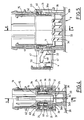
- Figure 4 is a sectional view along line 4-4 of Figure 5.
- Figure 5 is a sectional view along line 5-5 of Figure 4.
- Figure 6 is a view corresponding to Figure 4, the key being locked.
- Figure 7 is a view corresponding to Figure 5, the key being locked.
- FIG. 8 and Figure 9 are schematic views showing the locking of the female module.
- the connector shown in FIG. 3, comprises a male housing element 1 intended, at one end, to receive a male module 2 and, by the other end, a female housing element 3, said element 1 comprising, sliding mounted , a locking key 4.
- the element 1 comprises a first part 10 intended to receive the male module 2 and a housing 11 intended to receive the element of female housing 3 and the key 4.
- the male module 2 is divided into compartments 13 in each of which is housed a female electrical contact member 14 and extended by a part 18.
- Part 10 has a cavity 15 with a bottom 16 in the central part of which extends a skirt 17 corresponding to the lower part 18 of the male module 2 in order to receive the latter.
- the housing 11 of the housing 1 has a generally parallelepiped shape with two longitudinal walls 20 and 21 and two transverse walls 22 and 23.
- the female housing element 3 consists of a molded plastic body which has a bottom 33 from which erect male tongues 34 intended to be inserted into the female organs 14.
- the body has a cavity 36 divided into two parts, a part 36 a located in the vicinity of the free edge and a part 36 b situated in the vicinity of the bottom 33 smaller than the part 36 a and connected to the latter by a shoulder 38.
- the pins 31 are, in part, bordered by a bead 40.
- the key 4 is constituted by a molded plastic body having a U-shaped section with two branches 45 and a core 46.
- the spacing of the branches 45 corresponds to the spacing of the conduits 24.
- Each branch has grooves 47 in order to cooperate with the shoulders 26.
- Each branch 45 has two inclined ramps 48 which, at the lower end, open into notches 49, while the upper end ends in a part 50 provided with a notch 51 formed by a hollow extending in the direction of the edge provided with notches 49.
- the seal shown in Figures 1 and 2 consists of a sleeve 60 of a flexible and elastic material having, on its lateral surface, a series of toroids 61 and one of the ends of which ends in a flange 62 which has undulations 63 .
- the seal is intended to be mounted on the skirt 17, the rim 62 abutting against the external surface of the bottom 16.
Landscapes
- Connector Housings Or Holding Contact Members (AREA)
Claims (1)
- Elektrischer Verbinder, der einerseits eine Dichtung (60) und andererseits ein steckerartiges Gehäuseelement (1) besitzt, welches an einem Ende einen Raum (11) aufweist, der zur Aufnahme eines buchsenartigen Gehäuseelementes (3) bestimmt ist, das einen Hohlraum (36) aufweist, wobei der Raum durch einen Boden (16) abgeschlossen ist und ein innenliegendes Hemd (17) aufweist, das für den Eingriff in den Hohlraum (36) bestimmt ist, wobei das genannte steckerartige Gehäuseelement (1) zwei parallele Führungen (24) aufweist, die sich zum buchsenartigen Gehäuseelement senkrecht erstrecken und jede zur Aufnahme eines Schenkels (45) eines Schlüssels (4) bestimmt sind, jeder Schenkel (45) zwei geneigte Rampen (48) aufweist, die zur Zusammenwirkung mit Zapfen (31) des buchsenartigen Gehäuseelementes (3) bestimmt sind, jede Rampe (48), die in einer Raste (51) endigt, durch eine Aussparung in der Weise gebildet ist, daß die Verschiebung des Schlüssels in einer Richtung ein Eintreten des buchsenartigen Moduls (3) in den Raum (11) hervorruft, bis hin zu einer Verriegelungsstellung, in der die Zapfen (31) mit den Rasten (51) zusammenwirken, wobei die Dichtung (60) durch eine elastische Muffe gebildet ist, die an ihrem Umfang Wülste (61) aufweist, wobei die genannte Dichtung (60) auf dem genannten Hemd (17) so angeordnet ist, daß die genannten Wülste mit der inneren Oberfläche des Hohlraumes (36) des buchsenartigen Gehäuseelementes (3) zusammenwirken, welcher Verbinder dadurch gekennzeichnet ist, daß die Dichtung (60) an einem Ende eine seitliche Randleiste (62) aufweist, die zur Anlage am Boden (16) des Raumes, von welchem sich das Hemd (17) weg erstreckt, bestimmt ist, und daß diese Randleiste (62) mit Wölbungen (63) versehen ist, die die Elastizität der Randleiste erhöhen und dadurch die Verriegelung des Schlüssels verbessern.
Applications Claiming Priority (2)
| Application Number | Priority Date | Filing Date | Title |
|---|---|---|---|
| FR9402042A FR2716581B1 (fr) | 1994-02-23 | 1994-02-23 | Joint de connecteur électrique. |
| FR9402042 | 1994-02-23 |
Publications (2)
| Publication Number | Publication Date |
|---|---|
| EP0669680A1 EP0669680A1 (de) | 1995-08-30 |
| EP0669680B1 true EP0669680B1 (de) | 1996-12-11 |
Family
ID=9460343
Family Applications (1)
| Application Number | Title | Priority Date | Filing Date |
|---|---|---|---|
| EP19950400352 Expired - Lifetime EP0669680B1 (de) | 1994-02-23 | 1995-02-20 | Abdichtung für einen elektrischen Verbinder |
Country Status (3)
| Country | Link |
|---|---|
| EP (1) | EP0669680B1 (de) |
| DE (1) | DE69500105D1 (de) |
| FR (1) | FR2716581B1 (de) |
Families Citing this family (6)
| Publication number | Priority date | Publication date | Assignee | Title |
|---|---|---|---|---|
| DE29614501U1 (de) * | 1996-08-21 | 1996-10-02 | Dbt Deutsche Bergbau-Technik Gmbh, 42109 Wuppertal | Steckverbindung für elektronische Geräte u.dgl., insbesondere für Geräte im Untertagebergbau |
| GB2334632B (en) * | 1998-02-23 | 2002-03-13 | Delphi Automotive Systems Gmbh | Two-part electrical connector |
| DE19844693A1 (de) * | 1998-09-29 | 2000-03-30 | Delphi Automotive Systems Gmbh | Zweiteiliger elektrischer Verbinder |
| DE19844689A1 (de) * | 1998-09-29 | 2000-03-30 | Delphi Automotive Systems Gmbh | Elektrischer Verbinder mit einer Transportvorrichtung |
| FR2798517B1 (fr) * | 1999-09-15 | 2001-11-16 | Fci Automotive France | Connecteur a rampes avec un etrier d'insertion et de verrouillage, notamment pour une traversee de cloison |
| FR3039315B1 (fr) * | 2015-07-23 | 2019-06-21 | Leoni Wiring Systems France | Boitier pour fusible ameliore |
Family Cites Families (2)
| Publication number | Priority date | Publication date | Assignee | Title |
|---|---|---|---|---|
| US4917620A (en) * | 1987-10-28 | 1990-04-17 | Yazaki Corporation | Waterproof electrical connector |
| FR2694454B1 (fr) * | 1992-07-28 | 1994-09-16 | Cinch Connecteurs Sa | Connecteur électrique. |
-
1994
- 1994-02-23 FR FR9402042A patent/FR2716581B1/fr not_active Expired - Fee Related
-
1995
- 1995-02-20 DE DE69500105T patent/DE69500105D1/de not_active Expired - Lifetime
- 1995-02-20 EP EP19950400352 patent/EP0669680B1/de not_active Expired - Lifetime
Also Published As
| Publication number | Publication date |
|---|---|
| EP0669680A1 (de) | 1995-08-30 |
| FR2716581B1 (fr) | 1996-03-29 |
| FR2716581A1 (fr) | 1995-08-25 |
| DE69500105D1 (de) | 1997-01-23 |
Similar Documents
| Publication | Publication Date | Title |
|---|---|---|
| EP0152312B1 (de) | Elektrisches Kontaktteil | |
| EP0292394B1 (de) | Elektrische Verbindung | |
| FR2720197A1 (fr) | Connecteur pour câble électrique. | |
| EP0669680A1 (de) | Abdichtung für einen elektrischen Verbinder | |
| FR2519199A1 (fr) | Connecteur electrique | |
| EP0581638B1 (de) | Elektrischer Verbinder | |
| FR2699010A1 (fr) | Organe de contact électrique femelle. | |
| FR2669897A1 (fr) | Dispositif de verrouillage de deux elements de boitier l'un par rapport a l'autre. | |
| FR2729507A1 (fr) | Perfectionnements aux connecteurs electriques | |
| EP0660447B1 (de) | Verbesserungen an Gehäuseteilen von elektrischen Verbindern | |
| FR2698730A1 (fr) | Elément de boîtier de connecteur électrique et organe de contact électrique femelle destiné à être monté dans ledit élément de boîtier. | |
| FR2753008A1 (fr) | Obturateur de canaux de connecteurs electriques | |
| EP0694995B1 (de) | Dichtung für wasserdichten Steckverbinder | |
| EP1158634B1 (de) | Endstück für den Führungskanal elektrischer Leiter oder Kabel | |
| EP0462868A1 (de) | Verriegelungsvorrichtung für zwei Gehäuseteile eines elektrischen Verbinders | |
| FR2716298A1 (fr) | Perfectionnements aux connecteurs électriques. | |
| EP0477044A1 (de) | Verbesserungen in Bezug auf Gehäuseteile von elektrischen Verbindern | |
| FR2809872A1 (fr) | Dispositif de liaison electrique pour organe de contact electrique male et element de boitier destine a recevoir un tel dispositif | |
| EP0926770B1 (de) | Verbindungsvorrichtung mit rechtwinkliger Zusammenfügung, abgedichteter Stecker mit gesicherter doppelter Verriegelung | |
| FR2602945A1 (fr) | Dispositif de raccordement electrique du moteur d'un haut parleur | |
| EP1849216A1 (de) | Versiegelte verbindungseinrichtung und versiegeltes verbindergegenstück | |
| FR2797718A1 (fr) | Elements de boitier de connecteurs electriques | |
| EP0874431B1 (de) | Elektrischer Winkelstecker | |
| FR2737349A1 (fr) | Element de boitier de connecteur electrique | |
| EP0674357B1 (de) | Gehäuseteilen von elektrischen Verbindern |
Legal Events
| Date | Code | Title | Description |
|---|---|---|---|
| PUAI | Public reference made under article 153(3) epc to a published international application that has entered the european phase |
Free format text: ORIGINAL CODE: 0009012 |
|
| AK | Designated contracting states |
Kind code of ref document: A1 Designated state(s): DE GB IT |
|
| 17P | Request for examination filed |
Effective date: 19950916 |
|
| GRAG | Despatch of communication of intention to grant |
Free format text: ORIGINAL CODE: EPIDOS AGRA |
|
| GRAH | Despatch of communication of intention to grant a patent |
Free format text: ORIGINAL CODE: EPIDOS IGRA |
|
| 17Q | First examination report despatched |
Effective date: 19960506 |
|
| GRAH | Despatch of communication of intention to grant a patent |
Free format text: ORIGINAL CODE: EPIDOS IGRA |
|
| GRAA | (expected) grant |
Free format text: ORIGINAL CODE: 0009210 |
|
| AK | Designated contracting states |
Kind code of ref document: B1 Designated state(s): DE GB IT |
|
| GBT | Gb: translation of ep patent filed (gb section 77(6)(a)/1977) |
Effective date: 19961115 |
|
| REF | Corresponds to: |
Ref document number: 69500105 Country of ref document: DE Date of ref document: 19970123 |
|
| ITF | It: translation for a ep patent filed | ||
| PG25 | Lapsed in a contracting state [announced via postgrant information from national office to epo] |
Ref country code: DE Effective date: 19970312 |
|
| PLBE | No opposition filed within time limit |
Free format text: ORIGINAL CODE: 0009261 |
|
| STAA | Information on the status of an ep patent application or granted ep patent |
Free format text: STATUS: NO OPPOSITION FILED WITHIN TIME LIMIT |
|
| 26N | No opposition filed | ||
| PG25 | Lapsed in a contracting state [announced via postgrant information from national office to epo] |
Ref country code: GB Free format text: LAPSE BECAUSE OF NON-PAYMENT OF DUE FEES Effective date: 19990220 |
|
| GBPC | Gb: european patent ceased through non-payment of renewal fee |
Effective date: 19990220 |
|
| PG25 | Lapsed in a contracting state [announced via postgrant information from national office to epo] |
Ref country code: IT Free format text: LAPSE BECAUSE OF NON-PAYMENT OF DUE FEES;WARNING: LAPSES OF ITALIAN PATENTS WITH EFFECTIVE DATE BEFORE 2007 MAY HAVE OCCURRED AT ANY TIME BEFORE 2007. THE CORRECT EFFECTIVE DATE MAY BE DIFFERENT FROM THE ONE RECORDED. Effective date: 20050220 |