EP0669746A1 - Personalcomputer mit einer Verbindung zu einem Kommunikationsendgerät eines drahtlosen Fernsprechsystems - Google Patents
Personalcomputer mit einer Verbindung zu einem Kommunikationsendgerät eines drahtlosen Fernsprechsystems Download PDFInfo
- Publication number
- EP0669746A1 EP0669746A1 EP95102512A EP95102512A EP0669746A1 EP 0669746 A1 EP0669746 A1 EP 0669746A1 EP 95102512 A EP95102512 A EP 95102512A EP 95102512 A EP95102512 A EP 95102512A EP 0669746 A1 EP0669746 A1 EP 0669746A1
- Authority
- EP
- European Patent Office
- Prior art keywords
- personal computer
- communication terminal
- communication system
- connection
- communication
- Prior art date
- Legal status (The legal status is an assumption and is not a legal conclusion. Google has not performed a legal analysis and makes no representation as to the accuracy of the status listed.)
- Granted
Links
Images
Classifications
-
- H—ELECTRICITY
- H04—ELECTRIC COMMUNICATION TECHNIQUE
- H04M—TELEPHONIC COMMUNICATION
- H04M1/00—Substation equipment, e.g. for use by subscribers
- H04M1/72—Mobile telephones; Cordless telephones, i.e. devices for establishing wireless links to base stations without route selection
- H04M1/725—Cordless telephones
-
- H—ELECTRICITY
- H04—ELECTRIC COMMUNICATION TECHNIQUE
- H04M—TELEPHONIC COMMUNICATION
- H04M1/00—Substation equipment, e.g. for use by subscribers
- H04M1/72—Mobile telephones; Cordless telephones, i.e. devices for establishing wireless links to base stations without route selection
- H04M1/724—User interfaces specially adapted for cordless or mobile telephones
- H04M1/72403—User interfaces specially adapted for cordless or mobile telephones with means for local support of applications that increase the functionality
- H04M1/72409—User interfaces specially adapted for cordless or mobile telephones with means for local support of applications that increase the functionality by interfacing with external accessories
-
- H—ELECTRICITY
- H04—ELECTRIC COMMUNICATION TECHNIQUE
- H04M—TELEPHONIC COMMUNICATION
- H04M1/00—Substation equipment, e.g. for use by subscribers
- H04M1/26—Devices for calling a subscriber
- H04M1/27—Devices whereby a plurality of signals may be stored simultaneously
- H04M1/274—Devices whereby a plurality of signals may be stored simultaneously with provision for storing more than one subscriber number at a time, e.g. using toothed disc
- H04M1/2745—Devices whereby a plurality of signals may be stored simultaneously with provision for storing more than one subscriber number at a time, e.g. using toothed disc using static electronic memories, e.g. chips
-
- H—ELECTRICITY
- H04—ELECTRIC COMMUNICATION TECHNIQUE
- H04M—TELEPHONIC COMMUNICATION
- H04M2250/00—Details of telephonic subscriber devices
- H04M2250/08—Details of telephonic subscriber devices home cordless telephone systems using the DECT standard
-
- H—ELECTRICITY
- H04—ELECTRIC COMMUNICATION TECHNIQUE
- H04Q—SELECTING
- H04Q11/00—Selecting arrangements for multiplex systems
- H04Q11/04—Selecting arrangements for multiplex systems for time-division multiplexing
- H04Q11/0428—Integrated services digital network, i.e. systems for transmission of different types of digitised signals, e.g. speech, data, telecentral, television signals
Definitions
- the invention relates to a communication system with a personal computer, to which at least one communication terminal connected wirelessly to a base station is assigned, the base station being connected to a communication system.
- Wireless telephone systems comprise a base station - or a fixed part - to which one or more communication terminals - or mobile parts - are connected via a radio link.
- the radio transmission takes place, for example, according to the DECT standard (Digital European Cordless Telephony) or the GSM standard (Group Special Mobile).
- these standards define the channel structures for a wireless connection of several communication terminals.
- the base stations are using known transmission techniques - e.g. Analog or digital transmission methods - connected via one or more connections to a communication system - in particular a private branch exchange.
- the communication system is equipped with analog a / b interfaces or with digital ISDN interfaces.
- the communication terminal acts as a cordless handset for a personal computer - PC telephone - additional programs and a telephone card are installed in it, to which both the communication system and the base station connected.
- This assignment leads to the connection of a base station through the personal computer, so that the signaling from the communication terminal to the communication system and vice versa is read in the personal computer and can be visualized and influenced on its screen.
- the signaling for the associated communication terminal can be handled entirely by the personal computer.
- the signaling information - e.g. Dialing information - user interface controlled in personal computer - e.g. using the input keyboard - formed and transmitted to the communication system. Due to the convenient user interface and visualization on the screen of the personal computer, convenient signaling is achieved for the assigned communication terminals and, in addition, different functions that support the signaling - e.g. a telephone directory with search procedures - easy to implement.
- Such a communication arrangement of a personal computer with an associated wireless telephone system requires a considerable amount of programming and circuitry in the personal computer - additional telephone card including the programs.
- the object on which the invention is based is to reduce the effort for assigning a communication terminal of a wireless telephone system to a personal computer.
- the object is achieved on the basis of a communication system in accordance with the features of the preamble of patent claim 1 by its characterizing features.
- the at least one communication terminal can be connected to the personal computer via a connection, and that the at least one communication terminal is designed such that the signaling information transmitted wirelessly from the communication system to this communication terminal via the connection to the Personal computer and / or signaling information formed or stored in this communication terminal or formed or stored in the personal computer and transmitted via the connection can be controlled to the communication system.
- the signaling information (si) formed or stored in the at least one communication terminal (KE) can be transmitted and / or transmitted to the personal computer (PC) via the connection (SL, DÜ) and / or by the personal computer (PC) via the connection (SL, DÜ) to the at least one communication terminal (KE) transmitted signaling information (si) can be visualized or stored in the latter - claim 2.
- an additional visualization of the formed in the communication terminal or stored signaling information in the personal computer enables a variety of further processing of the signaling information - for example additional storage for a redial or a phone book etc.
- connection is realized by a flexible, pluggable line - claim 3 - or by a wireless transmission - claim 7.
- Advantageous wireless transmission systems are the infrared and the radio transmission system. It should be noted here that, particularly when using a radio transmission system, the radio properties, ie in particular the radio frequency, are determined such that the wireless transmission between the base station and the at least one wirelessly connected communication terminal not affected flows or remains undisturbed.
- the realization of the connection by flexible, pluggable lines or by wireless connections requires signaling interfaces or internal signaling interfaces both in the personal computer and in the communication terminals.
- a signaling interface is advantageously implemented by a serial data interface which is suitable for personal computers - claims 4 to 6 and 9.
- a complex telephone card in the personal computer can be dispensed with. Furthermore, with an advantageous use of a personal computer-based serial data interface, in particular the V.24 interface as a signaling interface, which is available in almost every personal computer, the assignment of a communication terminal of a wireless telephone system to a personal computer can be effected only by introducing suitable programs.
- the communication system concept according to the invention with signaling interfaces in the communication terminal and in the personal computer represents a particularly economical concept.
- Another significant advantage of the concept according to the invention over a solution with telephone cards is the fact that in the event of a failure of the personal computer, the functionality of the assigned communication terminal is retained without restriction.
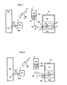
- Fig. 1 shows a communication system KA, to which a base station BS of a wireless telephone system is connected via a connecting line ASL.
- the communication system KA represents, for example, a private telecommunication private branch exchange system which is equipped with an ISDN-compliant SO interface SO for the connection of the base station BS.
- the base station BS has an SO interface SO that is implemented in the same way.
- a communication terminal KE is shown as an example.
- the radio link and the channel structures within the radio link are implemented in accordance with the DECT standard. This means that twelve communication terminals KE with bidirectional voice transmission can be connected wirelessly to the base station BS without blocking.
- the signaling information si formed in the communication terminals KE and transmitted by the communication system KA and the bidirectional voice information spi are transmitted via the radio link.
- the communication terminal KE additionally has a signaling interface SIS, which is connected to a similar signaling interface SIS of a personal computer PC.
- This signaling interface SIS is advantageously implemented by a CCITT interface V.24, which is usually available in a personal computer PC.
- the signaling interface SIS is implemented by an interface module V.24.
- the signaling interface SIS is physically implemented, that is, the interface lines are installed and the properties of the communication terminal internal or personal computer internal signaling interface ISI are adapted to the electrical properties of the signaling interface SIS.
- the signaling interface SIS of the communication terminal KE and that of the personal computer PC are connected via a flexible line SL.
- This flexible line SL is designed in accordance with the signaling interface SIS - in particular the number of wires - and has at least one plug element ST.
- the plug element ST faces either the communication terminal KE or the personal computer PC.
- the signaling interface SIS on the personal computer PC or on the communication terminal KE is realized by a mating plug element designed for the plug element ST.
- the signaling interface SIS on the communication terminal KE is advantageously designed as a plug connection ST, since in this case the mobility of the communication terminal KE remains largely intact.
- both signaling interfaces SIS can be implemented using ST plug connections.
- the interface module V.24 is connected to a microprocessor system CPU in the personal computer PC via the internal signaling interface ISI.
- a personal computer PC also has an input device EE - the known input keyboard or mouse - and a screen device BE.
- a signaling routine SR which is stored in a memory SP of the microprocessor system CPU and which, for example, signaling information input using the input device EE, is e.g. Dialing information - controlled to the screen device BE and displayed there.
- signaling information si e.g. a phone number that can be selected and displayed on the screen device BE.
- the signaling information si is transmitted wirelessly via the communication terminal KE to the base station BS and from there to the communication system KA and evaluated in the sense of establishing a connection, for example with a further communication terminal KE, not shown, connected to the communication system KA.
- FIG. 2 shows a communication system implemented in the same way as in FIG. 1, but instead of the flexible line SL with at least one plug element ST, a further wireless transmission system DÜ is provided.
- the wireless transmission system DÜ each has a transceiver SE, which is, for example, each connected to the signaling interface SIS.
- the transmitter / receiver device can, if configured appropriately, alternatively be connected directly to the signaling interface ISI internal to the personal computer and communication terminal.
- the internal signaling interface ISI corresponds procedurally to the signaling interface SIS, and in terms of its physical characteristics it is adapted to the internal physical conditions - in particular electrical properties.
- the V.24 interface module V.24 can be dispensed with.
- the transmission / reception device SE is formed by known transmission and reception devices for wireless transmission.
- infrared transmission and reception devices are preferably provided, since in the case of convenient signaling for an assigned communication terminal KE, this is in the immediate vicinity of the personal computer PC.
- Using a wireless infrared transmission system offers the additional advantage that the high-frequency, wireless transmission between the communication terminal KE and the base station BS remains unaffected, i.e. is not disturbed.
- the transmitting and receiving device can be implemented by means of further high-frequency, wireless transmitting / receiving devices SE. It should be noted here that the transmission frequency in particular is determined in such a way that the wireless transmission between the base station BS and the communication terminal KE remains unaffected.
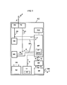
- Fig. 3 shows a block diagram of a communication terminal KE for wireless transmission of the signaling information si to or from the personal computer PC.
- the communication terminal KE has a microprocessor MP with an associated clock and audio tone device THE, a receiving and transmitting part RX, TX, a hearing device HE, a microphone device ME, a power supply SV, an input module TF equipped with a display unit AZ, an interface module SM and a transmitting / receiving device SE.
- the microphone device ME the signals emitted by a microphone are amplified, compressed and structured with the aid of a mixer, for example according to the DECT standard, and converted into high-frequency signals and fed to the transmitting part TX which is implemented, for example, according to the DECT standard.
- these signals are additionally controlled to the microprocessor MP.
- the DECT-compliant, high-frequency signals are transmitted wirelessly to the base station BS via an antenna A.
- the hearing device HE the high-frequency signals transmitted by the microprocessor MP or by the receiving part RX are amplified, demodulated, decompressed, in turn amplified and transmitted to a hearing device.
- the hearing device HE and the microphone device ME are each connected to the microprocessor MP via a control line STL.
- the operating voltages US for the individual components of the communication terminal KE are formed and in the power supply SV regulated.
- the power supply SV comprises an accumulator and a charging device provided therefor - not shown.
- the clock signals required for the operation of the microprocessor MP and, fairly, an output provided on the hearing device HE are formed in the clock and audio tone device THE and transmitted to the microprocessor.
- the microprocessor MP additionally has a serial, internal signaling interface ISI for the transmission of signaling information si.
- This interface ISI is connected to a similarly implemented interface ISI of an interface module SM.
- the signaling information si is adapted to a signaling interface SIS with regard to its physical properties.
- This signaling interface SIS is connected to a similarly implemented signaling interface SIS of the transceiver SE, the signaling interface SIS preferably being implemented by a V.24 interface.
- the transmitter / receiver device SE is formed by an infrared transmitter / receiver device, not shown.
- the sanding and receiving elements TRE e.g. an infrared transmitting diode and an infrared receiving diode, arranged on the outer wall of the communication terminal KE.
- the signaling information si formed in this communication terminal KE is sent wirelessly to the via the interface module SM and the transceiver SE Personal computer PC transmitted.
- the signaling information si formed or stored in the personal computer PC and transmitted wirelessly is controlled wirelessly to the base station BS via the transceiver SE and the interface module SM and with the aid of the control routine SR.
- the signaling information si transmitted by the personal computer PC can additionally be visualized on the display device AZ arranged in the input module TF.
- the transmitting / receiving device SE provided for infrared transmission
- high-frequency transmitting and receiving devices can be used.
- a further antenna must be implemented for the wireless transmission of the communication terminal device KE base station BS.
- the transceiver is to be dimensioned such that the transmission signals for the wireless transmission of the signaling information si between the personal computer PC and the communication terminal KE do not influence the wireless transmission between the communication terminal KE and the base station BS, i.e. to disturb.
Landscapes
- Engineering & Computer Science (AREA)
- Computer Networks & Wireless Communication (AREA)
- Signal Processing (AREA)
- Human Computer Interaction (AREA)
- Mobile Radio Communication Systems (AREA)
- Telephonic Communication Services (AREA)
Abstract
Description
- Die Erfindung betrifft ein Kommunikationssystem mit einem Personalcomputer, dem zumindest ein drahtlos an eine Basisstation angeschlossenes Kommunikationsendgerät zugeordnet ist, wobei die Basisstation mit einer Kommunikationsanlage verbunden ist.
- Drahtlose Fernsprechsysteme umfassen eine Basisstation - bzw. ein Festteil -, an die über eine Funkverbindung ein oder mehrere Kommunikationsendgeräte - bzw. Mobilteile - angeschlossen sind. Die Funkübertragung erfolgt beispielsweise gemäß dem DECT - Standard (Digital European Cordless Telephony) oder dem GSM - Standard (Group Special Mobile). In diesen Standards sind neben den funktechnischen Festlegungen die Kanalstrukturen für einen drahtlosen Anschluß mehrerer Kommunikationsendgeräte definiert. Die Basisstationen sind mit Hilfe bekannter Übertragungstechniken - z.B. analoge oder digitale Übertragungsverfahren - über ein oder mehrere Verbindungen mit einer Kommunikationsanlage - insbesondere einer Fernsprechnebenstellenanlage - verbunden. Hierzu ist die Kommunikationsanlage mit analogen a/b - Schnittstellen oder mit digitalen ISDN - Schnittstellen ausgestattet.
- Bei einer Zuordnung eines Kommunikationsendgerätes eines drahtlosen Fernsprechsystems zu einem Personalcomputer, bei dem das Kommunikationsendgerät im Sinne eines schnurlosen Hörers für einen Personalcomputer wirkt - PC-Telefon -, sind in diesem zusätzliche Programme und eine Fernsprechkarte installiert, an die sowohl die Kommunikationsanlage als auch die Basisstation angeschlossen ist. Durch diese Zuordnung wird der Anschluß einer Basisstation durch den Personalcomputer geführt, wodurch die Signalisierung vom Kommunikationsendgerät zur Kommunikationsanlage und umgekehrt im Personalcomputer mitgelesen, an dessen Bildschirm visualisiert und beeinflußt werden kann. Darüberhinaus kann die Signalisierung für das zugeordnete Kommunikationsendgerät vollständig durch den Personalcomputer abewickelt werden. Dies bedeutet, daß die Signalisierungsinformationen - z.B. Wahlinformationen - in Personalcomputer bedieneroberflächengesteuert - z.B. mit Hilfe der Eingabetastatur - gebildet und an die Kommunikationsanlage übermittelt werden. Aufgrund der komfortablen Bedieneroberfläche und Visualisierung am Bildschirm des Personalcomputers wird eine komfortable Signalisierung für die zugeordneten Kommunikationsendgeräte erreicht und zusätzlich sind unterschiedliche, die Signalisierung unterstützende Funktionen - z.B. ein Telefonverzeichnis mit Suchprozeduren - komfortabel realisierbar.
- Eine derartige Kommunikationsanordnung eines Personalcomputers mit einem zugeordneten drahtlosen Fernsprechsystem erfordert einen erheblichen programmtechnischen und schaltungstechnischen Aufwand im Personalcomputer - zusätzliche Fernsprechkarte einschließlich der Programme.
- Die der Erfindung zugrundeliegende Aufgabe besteht darin, den Aufwand für eine Zuordnung eines Kommunikationsendgerätes eines drahtlosen Fernsprechsystems zu einem Personalcomputer zu vermindern. Die Aufgabe wird ausgehend von einem Kommunikationssystem gemäß den Merkmalen des Oberbegriffs des Patentanspruchs 1 durch dessen kennzeichnende Merkmale gelöst.
- Der wesentliche Aspekt der Erfindung ist darin zu sehen, daß das zumindest eine Kommunikationsendgerät an den Personalcomputer über eine Verbindung anschließbar ist, und daß das zumindest eine Kommunikationsendgerät derart ausgestaltet ist, daß die von der Kommunikationsanlage drahtlos an dieses Kommunikationsendgerät übermittelten Signalisierungsinformationen über die Verbindung an den Personalcomputer und/oder in diesem Kommunikationsendgerät gebildete oder gespeicherte oder im Personalcomputer gebildete oder gespeicherte und über die Verbindung übermittelte Signalisierungsinformationen an die Kommunikationsanlage gesteuert werden. Zusätzlich können die in dem zumindest einen Kommunikationsendgerät (KE) gebildeten oder gespeicherten Signalisierungsinformationen (si) über die Verbindung (SL,DÜ) an den Personalcomputer (PC) übermittelt und werden und/oder die vom Personalcomputer (PC) über die Verbindung (SL,DÜ) an das zumindest eine Kommunikationsendgerät (KE) übermittelten Signalisierungsinformationen (si) in diesem visualisiert oder gespeichert werden - Anspruch 2. Hierdurch ist zusätzlich eine Anzeige der gebildeten oder gespeicherten Signalisierungsinformationen in der jeweils anderen Einrichtung möglich.lnsbesondere eine zusätzliche Visualisierung der im Kommunikationsendgerät gebildeten oder gespeicherten Signalisierungsinformationen im Personalcomputer ermöglicht eine vielfältige Weiterverarbeitung der Signalisierungsinformationen - z.B. zusätzliche Speicherung für eine Wahlwiederholung oder ein Telefonbuch usw.
- Gemäß vorteilhafter Weiterbildungen der Erfindung ist die Verbindung durch eine flexible, steckbare Leitung - Anspruch 3 - oder durch eine drahtlose Übertragung - Anspruch 7 - realisiert. Vorteilhafte drahtlose Übertragungssysteme stellen das Infrarot- und das Funkübertragungssystem - Anspruch 8 - dar. Zu beachten ist hierbei, daß insbesondere bei einem Einsatz eines Funkübertragungssystems die Funkeigenschaften, d.h. insbesondere die Funkfrequenz derart bestimmt sind, daß die drahtlose Übertragung zwischen der Basisstation und dem zumindest einem drahtlos angeschlossenen Kommunikationsendgerät nicht beeinflußt wird bzw. ungestört bleibt. Die Realisierungen der Verbindung durch flexible, steckbare Leitungen oder durch drahtlose Verbindungen setzen sowohl im Personalcomputer als auch in den Kommunikationsendgeräten jeweils Signalisierungsschnittstellen bzw. interne Signalisierungsschnittstellen voraus. Eine Signalisierungsschnittstelle ist vorteilhaft durch eine personalcomputergerechte serielle Datenschnittstelle realisiert - Ansprüche 4 bis 6 und 9.
- Durch die Verbindung zwischen dem Personalcomputer und einem zugeordneten Kommunikationsendgerät und dem Realisieren einer Signalsierungsschnittstelle in dem Kommunikationsendgerät und im Personalcomputer kann auf eine aufwendige Fernsprechkarte im Personalcomputer verzichtet werden. Desweiteren kann bei einer vorteilhaften Benutzung einer personalcomputergemäßen seriellen Datenschnittstelle, insbesondere die V.24-Schnittstelle als Signalisierungsschnittstelle, die in fast jedem Personalcomputer zur Verfügung steht, lediglich durch Einbringen geeigneter Programme die Zuordnung eines Kommunikationsendgerätes eines drahtlosen Fernsprechsystems zu einem Personalcomputer bewirkt werden. Da eine Realisierung der Signalisierungsschnittstelle im Kommunikationsendgerät des drahtlosen Fernsprechsystems aufgrund der bereits vorhandenen, mitbenutzbaren Komponenten durch erheblich geringeren, insbesondere schaltungstechnischen Aufwand gegenüber einer Realisierung mit einer Fernsprechkarte erreicht wird, stellt das erfindungsgemäße Kommunikationssystemkonzept mit Signalisierungsschnittstellen im Kommunikationsendgerät und im Personalcomputer eine besonders wirtschaftliche Konzeption dar. Ein weiterer wesentlicher Vorteil der erfindungsgemäßen Konzeption gegenüber einer Lösung mit Fernsprechkarten ist darin zu sehen, daß bei einem Ausfall des Personalcomputers die Funktionsfähigkeit des zugeordneten Kommunikationsendgerätes uneingeschränkt erhalten bleibt.
- Im folgenden wird das erfindungsgemäße Verfahren anhand dreier Blockschaltbilder näher erläutert. Dabei zeigen
- Fig. 1 ein Kommunikationssystem mit einer Kommunikationsanlage, einer Basisstation und mit einem mit einem Kommunikationsendgerät verbundenen Personalcomputer,
- Fig. 2 ein Kommunikationssystem mit einer Kommunikationsanlage, einer Basisstation und mit einem mit einem Kommunikationsendgerät "drahtlos" verbundenen Personalcomputer, und
- Fig. 3 ein Blockschaltbild eines Kommunikationsendgerätes.
- Fig. 1 zeigt eine Kommunikationsanlage KA, an die über eine Anschlußleitung ASL eine Basisstation BS eines drahtlosen Fernsprechsystems angeschlossen ist. Die Kommunikationsanlage KA stellt beispielsweise eine private Fernmeldenebenstellenanlage dar, die für den Anschluß der Basisstation BS mit einer ISDN-gemäßen SO-Schnittstelle SO ausgestattet ist. Analog hierzu weist die Basisstation BS eine gleichartig realisierte SO-Schnittstelle SO auf.
- An die Basisstation BS ist drahtlos, d.h. über eine Funkverbindung, zumindest ein Kommunikationsendgerät KE angeschlossen - im Ausführungsbeispiel ist beispielhaft ein Kommunikationsendgerät KE dargestellt. Für das Ausführungsbeispiel sei weiterhin angenommen, daß die Funkverbindung und die Kanalstrukturen innerhalb der Funkverbindung gemäß dem DECT-Standard realisiert sind. Dies bedeutet, daß an die Basisstation BS drahtlos zwölf Kommunikationsendgeräte KE mit bidirektionaler Sprachübertragung blockierungsfrei anschließbar sind. Über die Funkverbindung werden die in den Kommunikationsendgeräten KE gebildeten und die von der Kommunikationsanlage KA übermittelten Signalisierungsinformationen si sowie die bidirektional zu übermittelnden Sprachinformationen spi übertragen.
- Das Kommunikationsendgerät KE weist zusätzlich eine Signalisierungsschnittstelle SIS auf, die mit einer gleichartigen Signalisierungsschnittstelle SIS eines Personalcomputers PC verbunden ist. Vorteilhaft ist diese Signalisierungsschnittstelle SIS durch eine CCITT-Schnittstelle V.24 realisiert, die in einem Personalcomputer PC üblicherweise verfügbar ist. Im Personalcomputer PC und im Kommunikationsendgerät KE ist die Signalisierungsschnittstelle SIS durch ein Schnittstellenmodul V.24 realisiert. In diesem Schnittstellenmodul V.24 wird die Signalisierungsschnittstelle SIS physikalisch realisiert, d.h. die Schnittstellenleitungen installiert und die Eigenschaften der kommunikationsendgeräteinternen bzw. der personalcomputerinternen Signalisierungsschnittstelle ISI werden an die elektrischen Eigenschaften der Signalisierungsschnittstelle SIS angepaßt. Die Signalisierungsschnittstelle SIS des Kommunikationsendgerätes KE und die des Personalcomputers PC sind über eine flexible Leitung SL verbunden. Diese flexible Leitung SL ist entsprechend der Signalisierungsschnittstelle SIS ausgestaltet - insbesondere Anzahl der Drähte - und weist zumindest ein Steckelement ST auf. Das Steckelement ST ist entweder dem Kommunikationsendgerät KE oder dem Personalcomputer PC zugewandt. Dies bedeutet, das die Signalisierungsschnittstelle SIS am Personalcomputer PC oder am Kommunikationsendgerät KE durch eine zum Steckelement ST ausgebildetes Gegensteckelement realisiert ist. Vorteilhaft ist die Signalisierungsschnittstelle SIS am Kommunikationsendgerät KE als eine Steckverbindung ST ausgestaltet, da hierbei die Mobilität des Kommunikationsendgerätes KE weitgehend erhalten bleibt. Alternativ sind beide Signalisierungsschnittstellen SIS durch Steckverbindungen ST realisierbar.
- Das Schnittstellenmodul V.24 ist im Personalcomputer PC über die interne Signalisierungsschnittstelle ISI mit einem Mikroprozessorsystem CPU verbunden. Ein Personalcomputer PC weist bekannterweise weiterhin eine Eingabeeinrichtung EE - die bekannte Eingabetastatur bzw. Maus - und eine Bildschirmeinrichtung BE auf.
- Erfindungsgemäß werden mit einer in einem Speicher SP des Mikroprozessorsystems CPU gespeicherten Signalisierungsroutine SR, die beispielsweise mit Hilfe der Eingabeeinrichtung EE eingegebenen Signalisierungsinformationen si - z.B. Wählinformationen - an die Bildschirmeinrichtung BE gesteuert und dort angezeigt. Alternativ ist mit Hilfe der Signalisierungsroutine SR beispielsweise aus einem im Speicher SP gespeicherten Telefonbuch eine Signalisierungsinformation si, d.h. eine Rufnummer, auswählbar und an der Bildschirmeinrichtung BE anzeigbar. Nach einer weiteren Eingabe werden die Signalisierungsinformationen si über das Kommunikationsendgerät KE drahtlos an die Basisstation BS und von dort an die Kommunikationsanlage KA übermittelt und in dieser im Sinne eines Verbindungsaufbaus beispielsweise mit einem weiteren, an der Kommunikationsanlage KA angeschlossenen, nicht dargestellten Kommunikationsendgerät KE bewertet. Dies bedeutet, daß für eines der diesem Personalcomputer PC zugeordneten Kommunikationsendgeräte KE ein Verbindungsaufbau auf komfortable Weise durchgeführt werden kann. Des weiteren können zusätzliche Leistungsmerkmale während oder vor einer Kommunikationsbeziehung zwischen den Kommunikationsendgeräten KE mit Hilfe des Personalcomputers PC aufgrund zusätzlich implementierter Bedienerführungsroutinen wesentlich komfortabler gesteuert werden.
- Fig. 2 zeigt ein gleichartig wie in Fig. 1 realisiertes Kommunikationssystem, jedoch ist anstelle der flexiblen Leitung SL mit zumindest einem Steckelement ST ein weiteres drahtloses Übertragungssystem DÜ vorgesehen. Das drahtlose Übertragungssystem DÜ weist jeweils eine Sende-/Empfangseinrichtung SE auf, die beispielsweise jeweils mit der Signalisierungsschnittstelle SIS verbunden ist. Die Sende- /Empfangseinrichtung ist bei entsprechender Ausgestaltung alternativ direkt an die personalcomputer- und kommunikationsendgeräteintere Signalisierungsschnittstelle ISI anschließbar. Hierbei entspricht die interne Siegnalisierungsschnittstelle ISI prozedural der Signalisierungsschnittstelle SIS und hinsichtlich der physikalischen Ausprägung ist sie an die internen physikalischen Bedingungen - insbesondere elektrische Eigenschaften - angepaßt. Bei einem Anschluß der Sende-/Empfangseinrichtung SE an die interne Signalisierungsschnittstelle ISI kann auf das V.24-Schnittstellenmodul V.24 verzichtet werden.
- Die Sende-/Empfangseinrichtung SE ist durch bekannte Sende- und Empfangseinrichtungen für eine drahtlose Übertragung gebildet. Vorzugsweise sind hierbei Infrarotsende- und Empfangseinrichtung vorgesehen, da bei einer komfortablen Signalisierung für ein zugeordnetes Kommunikationsendgerät KE sich dieses in unmittelbarer Nähe des Personalcomputers PC befindet. Eine Benutzung eines drahtlosen Infrarotübertragungssystem bietet zusätzlich den Vorteil, daß die hochfrequente, drahtlose Übertragung zwischen dem Kommunikationsendgerät KE und der Basisstation BS unbeeinflußt bleibt, d.h. nicht gestört wird. Alternativ sind die Sende- und Empfangseinrichtung durch weitere hochfrequente, drahtlose Sende-/Empfangseirichtungen SE realisierbar. Zu beachten ist hierbei, daß insbesondere die Übertragungsfrequenz derart bestimmt ist, daß die drahtlose Übertragung zwischen der Basisstation BS und dem Kommunikationsendgerät KE unbeeinflußt bleibt.
- Fig. 3 zeigt ein Blockschaltbild eines Kommunikationsendgerätes KE für eine drahtlose Übermittlung der Signalisierungsinformationen si an den bzw. vom Personalcomputer PC. Das Kommunikationsendgerät KE weist einen Mikroprozessor MP mit einer zugeordneten Takt- und Hörtoneinrichtung THE, ein Empfangs- und Sendeteil RX, TX, eine Höreinrichtung HE, eine Mikrofoneinrichtung ME, eine Stromversorgung SV, ein mit einer Anzeigeeinheit AZ ausgestattetes Eingabemodul TF, ein Schnittstellenmodul SM und eine Sende-/Empfangseinrichtung SE auf. In der Mikrofoneinrichtung ME werden die von einem Mikrofon abgegebenen Signale verstärkt, komprimiert und mit Hilfe eines Mischers beispielsweise gemäß dem DECT-Standard strukturiert sowie in hochfrequente Signale umgesetzt und dem beispielsweise gemäß dem DECT-Standard realisierten Sendeteil TX zugeführt. Zur Überwachung und weiteren Steuerung werden diese Signale zusätzlich an den Mikroprozessor MP gesteuert. Über eine Antenne A werden die DECT-gemäßen, höchstfrequenten Signale an die Basisstation BS drahtlos übertragen.
- In der Höreinrichtung HE werden die vom Mikroprozessor MP oder die vom Empfangsteil RX übermittelten höchfrequenten Signale verstärkt, demoduliert, dekomprimiert, wiederum verstärkt und an eine Höreinrichtung übermittelt. Zur Steuerung und Überwachung ist die Höreinrichtung HE und die Mikrofoneinrichtung ME jeweils über eine Steuerleitung STL mit dem Mikroprozessor MP verbunden.
- In der Stromversorgung SV werden die Betriebsspannungen US für die einzelnen Komponenten des Kommunikationsendgerätes KE gebildet und geregelt. Die Stromversogung SV umfaßt einen Akkumulator und eine hierfür vorgesehene Ladeeinrichtung - nicht dargestellt.
- In der Takt- und Hörtoneinrichtung THE werden die für den Betrieb des Mikroprozessors MP erforderlichen Taktsignale und fair eine Ausgabe an der Höreinrichtung HE vorgesehenen Hörtonsignale gebildet und an den Mikroprozessor übermittelt.
- Der Mikroprozessor MP weist zusätzlich eine serielle, interne Signalisierungsschnittstelle ISI für die Übermittlung von Signalisierungsinformationen si auf. Diese Schnittstelle ISI ist mit einer gleichartig realisierten Schnittstelle ISI eines Schnittstellenmoduls SM verbunden. In diesem Schnittstellenmodul SM werden die Signalisierungsinformationen si hinsichtlich ihrer physikalischen Eigenschaften an eine Signalisierungsschnittstelle SIS angepaßt. Diese Signalisierungsschnittstelle SIS ist mit einer gleichartig realisierten Signalisierungsschnittstelle SIS der Sende-/Empfangseinrichtung SE verbunden, wobei die Signalisierungsschnittstelle SIS vorzugsweise durch eine V.24-Schnittstelle realisiert wird. Für das Auführungsbeispiel sei angenommen, daß die Sende-/Empfangseinrichtung SE durch eine nicht dargestellte Infrarotsende-/Empfangseinrichtung gebildet ist. Hierbei sind die Sande- und Empfangselemente TRE, z.B. eine Infrarotsendediode und eine Infrarotempfangsdiode, an der Außenwand des Kommunikationsendgerätes KE angeordnet.
- Mit Hilfe einer in einem Speicher SP des Mikroprozessors MP gespeicherten Steuerungsroutine STR werden die in diesem Kommunikationsendgerät KE beispielsweise im Eingabemodul TF durch eine Tastatur gebildeten oder von der Basisstation BS drahtlos empfangenen Signalisierungsinformationen si über das Schnittstellenmodul SM und die Sende-/Empfangseinrichtung SE drahtlos an den Personalcomputer PC übermittelt. Analog hierzu werden die im Personalcomputer PC gebildeten oder gespeicherten sowie drahtlos übermittelten Signalisierungsinformationen si über die Sende-/Empfangseinrichtung SE und das Schnittstellenmodul SM und mit Hilfe der Steuerungsroutine SR drahtlos an die Basisstation BS gesteuert. Die vom Personalcomputer PC übermittelten Signalisierungsinformationen si sind zusätzlich an der im Eingagemodul TF angeordneten Anzeigeeinrichtung AZ visualisierbar. Anstelle der für eine Infrarotübertragung vorgesehenen Sende-/Empfangseinrichtung SE sind hochfrequente Sende- und Empfangseinrichtungen einsetzbar. Hierzu ist zusätzlich zur Antenne A für die drahtlose Übermittlung Kommunikationsendgerät KE - Basisstation BS eine weitere Antenne zu implementieren. Hierbei ist die Sende-/Empfangseinrichtung derart zu dimensionieren, daß die Übertragungssignale für die drahtlose Übertragung der Signalisierungsinformationen si zwischen dem Personalcomputer PC und dem Kommunikationsendgerät KE die drahtlose Übertragung zwischen dem Kommunikationsendgerät KE und der Basisstation BS nicht beeinflussen, d.h. stören.
Claims (9)
dadurch gekennzeichnet,
gesteuert werden.
dadurch gekennzeichnet, daß das zumindest eine Kommunikationsendgerät (KE) derart ausgestaltet ist, daß die in dem zumindest einen Kommunikationsendgerät (KE) gebildeten oder gespeicherten Signalisierungsinformationen (si) zusätzlich über die Verbindung (SL,DÜ) an den Personalcomputer (PC) übermittelt werden und/oder die vom Personalcomputer (PC) über die Verbindung (SL,DÜ) an das zumindest eine Kommunikationsendgerät (KE) übermittelten Signalisierungsinformationen (si) in diesem visualisiert oder speichert werden.
dadurch gekennzeichnet, daß die Verbindung (SL,DÜ) zwischen dem Personalcomputer (PC) und dem zumindest einen Kommunikationsendgerät (KE) durch eine flexible Leitung (SL) mit zumindest einer Steckverbindung (ST) realisiert ist.
dadurch gekennzeichnet, daß die flexible Leitung (SL) mit dem Personalcomputer (PC) und mit einem zugeordneten Kommunikationsendgerät (KE) jeweils über eine Signalisierungsschnittstelle (SIS) verbunden ist.
dadurch gekennzeichnet, daß die Signalisierungsschnittstelle (SIS) durch eine serielle, personalcomputergemäße Datenschnittstelle (V.24) realisiert ist.
dadurch gekennzeichnet, daß die personalcomputergemäße Datenschnittstelle (V.24) gemäß der CCITT-standardisierten V.24-Schnittstelle (V.24) realisiert ist.
dadurch gekennzeichnet, daß das zumindest eine Kommunikationsendgerät (KE) an den Personalcomputer (PC) durch eine drahtlose Verbindung (DÜ) anschließbar ist.
dadurch gekennzeichnet, daß die drahtlose Verbindung (DÜ) durch ein Infrarotübertragungssystem oder ein Funkübertragungssystem realisiert ist, wobei die Funk- übertragungseigenschaften derart bestimmt sind, daß die drahtlose Übertragung zwischen der Basisstation (BS) und den drahtlos angeschlossenen Kommunikationsendgeräten (KE) unbeeinflußt bleibt.
dadurch gekennzeichnet, daß das Infrarotübertragungssystem (DÜ) oder das Funkübertragungssystem (DÜ) im Personalcomputer (PC) und in dem zumindest einem Kommunikationsendgerät (KE) an eine interne Signalisierungsschnittstelle (ISI) angeschlossen ist.
Applications Claiming Priority (2)
| Application Number | Priority Date | Filing Date | Title |
|---|---|---|---|
| DE4406507 | 1994-02-28 | ||
| DE4406507A DE4406507C2 (de) | 1994-02-28 | 1994-02-28 | Personalcomputer mit einer Verbindung zu einem Kommunikationsendgerät eines drahtlosen Fernsprechsystems |
Publications (2)
| Publication Number | Publication Date |
|---|---|
| EP0669746A1 true EP0669746A1 (de) | 1995-08-30 |
| EP0669746B1 EP0669746B1 (de) | 1997-06-04 |
Family
ID=6511414
Family Applications (1)
| Application Number | Title | Priority Date | Filing Date |
|---|---|---|---|
| EP95102512A Expired - Lifetime EP0669746B1 (de) | 1994-02-28 | 1995-02-22 | Personalcomputer mit einer Verbindung zu einem Kommunikationsendgerät eines drahtlosen Fernsprechsystems |
Country Status (3)
| Country | Link |
|---|---|
| EP (1) | EP0669746B1 (de) |
| AT (1) | ATE154186T1 (de) |
| DE (2) | DE4406507C2 (de) |
Cited By (13)
| Publication number | Priority date | Publication date | Assignee | Title |
|---|---|---|---|---|
| FR2728123A1 (fr) * | 1994-12-12 | 1996-06-14 | Nokia Mobile Phones Ltd | Procede de transmission de donnees |
| WO1997003532A1 (en) * | 1995-07-07 | 1997-01-30 | Datasoft Systems Ab | Arrangement for wireless communications |
| WO1997034403A1 (en) * | 1996-03-14 | 1997-09-18 | Telefonaktiebolaget Lm Ericsson (Publ) | An integrated local communication system |
| WO1998011707A1 (en) * | 1996-09-11 | 1998-03-19 | Telefonaktiebolaget Lm Ericsson (Publ) | An integrated local communication system |
| WO1999007128A1 (de) * | 1997-08-01 | 1999-02-11 | Siemens Aktiengesellschaft | Verfahren zum zugriff auf ein sortiertes telefonbuch in einem mobiltelefon über eine schnittstelle zur externen steuerung (remote control schnittstelle) durch die angabe eines oder mehrerer buchstaben als suchkriterium und anordnung zur durchführung des verfahrens |
| WO1999044350A1 (de) * | 1998-02-25 | 1999-09-02 | Rohde & Schwarz Gmbh & Co. Kg | Funkgerät mit fernbedienung |
| WO2000001132A1 (en) * | 1998-06-30 | 2000-01-06 | Paragon Software (Developments) Ltd. | Telephone directory management system having wireless telephone interface capability |
| DE19945666A1 (de) * | 1999-09-23 | 2001-01-11 | Siemens Ag | Basisstation sowie dazugehöriges Schnurlos-Kommunikationssystem |
| NL1013976C2 (nl) * | 1999-12-28 | 2001-06-29 | Koninkl Kpn Nv | Handterminal. |
| WO2001058039A3 (en) * | 2000-02-07 | 2002-05-02 | Qualcomm Inc | System and method for modularizing the functionality of an electronic device |
| EP0913984A3 (de) * | 1997-10-28 | 2003-06-25 | Alcatel | Digitales Telekommunikations-System mit DECT-Interface für Fax- und Datenanwendungen |
| EP1343301A1 (de) * | 1995-09-29 | 2003-09-10 | Siemens Aktiengesellschaft | Fernmeldegerät |
| EP1128644A3 (de) * | 2000-02-22 | 2003-09-17 | Sony Corporation | Kommunikationsendgerät |
Families Citing this family (1)
| Publication number | Priority date | Publication date | Assignee | Title |
|---|---|---|---|---|
| DE19648627C2 (de) * | 1996-11-12 | 2000-01-27 | Bosch Gmbh Robert | Kommunikationssystem zur Übertragung von multimedialen Daten |
Citations (4)
| Publication number | Priority date | Publication date | Assignee | Title |
|---|---|---|---|---|
| DE9215403U1 (de) * | 1992-11-12 | 1992-12-24 | Macht, Manfred, 8901 Adelsried | Funkkomforttelefon |
| WO1993007684A1 (en) * | 1991-10-07 | 1993-04-15 | Sixtel S.P.A. | Cordless local area network (radio lan) with central unit |
| EP0619669A2 (de) * | 1993-03-22 | 1994-10-12 | Ascom Business Systems Ag | Schnittstelleneinrichtung für Datenübertragungsfunkverbindung |
| EP0632636A1 (de) * | 1993-05-21 | 1995-01-04 | Hagenuk Telecom GmbH | Vorrichtung zur Kopplung |
Family Cites Families (2)
| Publication number | Priority date | Publication date | Assignee | Title |
|---|---|---|---|---|
| AU606358B2 (en) * | 1986-09-16 | 1991-02-07 | Alcatel Australia Limited | Communication interface |
| DE9113123U1 (de) * | 1991-10-22 | 1991-12-12 | Kluge, Norbert, Dipl.-Ing., 6301 Wettenberg | Tragbares Sende-/Empfangsmodul zum drahtlosen Austausch digitaler Informationen |
-
1994
- 1994-02-28 DE DE4406507A patent/DE4406507C2/de not_active Expired - Fee Related
-
1995
- 1995-02-22 DE DE59500275T patent/DE59500275D1/de not_active Expired - Lifetime
- 1995-02-22 AT AT95102512T patent/ATE154186T1/de not_active IP Right Cessation
- 1995-02-22 EP EP95102512A patent/EP0669746B1/de not_active Expired - Lifetime
Patent Citations (4)
| Publication number | Priority date | Publication date | Assignee | Title |
|---|---|---|---|---|
| WO1993007684A1 (en) * | 1991-10-07 | 1993-04-15 | Sixtel S.P.A. | Cordless local area network (radio lan) with central unit |
| DE9215403U1 (de) * | 1992-11-12 | 1992-12-24 | Macht, Manfred, 8901 Adelsried | Funkkomforttelefon |
| EP0619669A2 (de) * | 1993-03-22 | 1994-10-12 | Ascom Business Systems Ag | Schnittstelleneinrichtung für Datenübertragungsfunkverbindung |
| EP0632636A1 (de) * | 1993-05-21 | 1995-01-04 | Hagenuk Telecom GmbH | Vorrichtung zur Kopplung |
Non-Patent Citations (1)
| Title |
|---|
| W.S.HUI ET AL.: "CT2 BASE AND HANDSET WITH BUILT-IN MODEM", MOTOROLA TECHNICAL DEVELOPMENTS, vol. 20, SCHAUMBURG, ILLINOIS, US, pages 110 - 111, XP000403841 * |
Cited By (20)
| Publication number | Priority date | Publication date | Assignee | Title |
|---|---|---|---|---|
| GB2296161B (en) * | 1994-12-12 | 1999-10-20 | Nokia Mobile Phones Ltd | Data transmission method |
| WO1996019065A3 (en) * | 1994-12-12 | 1996-08-22 | Nokia Mobile Phones Ltd | Data transmission method |
| FR2728123A1 (fr) * | 1994-12-12 | 1996-06-14 | Nokia Mobile Phones Ltd | Procede de transmission de donnees |
| WO1997003532A1 (en) * | 1995-07-07 | 1997-01-30 | Datasoft Systems Ab | Arrangement for wireless communications |
| EP1343301A1 (de) * | 1995-09-29 | 2003-09-10 | Siemens Aktiengesellschaft | Fernmeldegerät |
| US5913163A (en) * | 1996-03-14 | 1999-06-15 | Telefonaktiebolaget Lm Ericsson | Integrated local communication system |
| US5983100A (en) * | 1996-03-14 | 1999-11-09 | Telefonaktiebolaget Lm Ericsson | Circuit assembly for effectuating communication between a first and a second locally-positioned communication device |
| AU719578B2 (en) * | 1996-03-14 | 2000-05-11 | Telefonaktiebolaget Lm Ericsson (Publ) | An integrated local communication system |
| WO1997034403A1 (en) * | 1996-03-14 | 1997-09-18 | Telefonaktiebolaget Lm Ericsson (Publ) | An integrated local communication system |
| WO1998011707A1 (en) * | 1996-09-11 | 1998-03-19 | Telefonaktiebolaget Lm Ericsson (Publ) | An integrated local communication system |
| AU719471B2 (en) * | 1996-09-11 | 2000-05-11 | Telefonaktiebolaget Lm Ericsson (Publ) | A circuit assembly for effectuating communication between a first and a second locally-positioned communication device |
| WO1999007128A1 (de) * | 1997-08-01 | 1999-02-11 | Siemens Aktiengesellschaft | Verfahren zum zugriff auf ein sortiertes telefonbuch in einem mobiltelefon über eine schnittstelle zur externen steuerung (remote control schnittstelle) durch die angabe eines oder mehrerer buchstaben als suchkriterium und anordnung zur durchführung des verfahrens |
| EP0913984A3 (de) * | 1997-10-28 | 2003-06-25 | Alcatel | Digitales Telekommunikations-System mit DECT-Interface für Fax- und Datenanwendungen |
| WO1999044350A1 (de) * | 1998-02-25 | 1999-09-02 | Rohde & Schwarz Gmbh & Co. Kg | Funkgerät mit fernbedienung |
| US6914888B1 (en) | 1998-02-25 | 2005-07-05 | Rohde & Schwarz Gmbh & Co. Kg | Radio device with remote control |
| WO2000001132A1 (en) * | 1998-06-30 | 2000-01-06 | Paragon Software (Developments) Ltd. | Telephone directory management system having wireless telephone interface capability |
| DE19945666A1 (de) * | 1999-09-23 | 2001-01-11 | Siemens Ag | Basisstation sowie dazugehöriges Schnurlos-Kommunikationssystem |
| NL1013976C2 (nl) * | 1999-12-28 | 2001-06-29 | Koninkl Kpn Nv | Handterminal. |
| WO2001058039A3 (en) * | 2000-02-07 | 2002-05-02 | Qualcomm Inc | System and method for modularizing the functionality of an electronic device |
| EP1128644A3 (de) * | 2000-02-22 | 2003-09-17 | Sony Corporation | Kommunikationsendgerät |
Also Published As
| Publication number | Publication date |
|---|---|
| DE59500275D1 (de) | 1997-07-10 |
| DE4406507C2 (de) | 1995-12-07 |
| DE4406507A1 (de) | 1995-08-31 |
| ATE154186T1 (de) | 1997-06-15 |
| EP0669746B1 (de) | 1997-06-04 |
Similar Documents
| Publication | Publication Date | Title |
|---|---|---|
| EP0669746B1 (de) | Personalcomputer mit einer Verbindung zu einem Kommunikationsendgerät eines drahtlosen Fernsprechsystems | |
| EP0369110B1 (de) | Mobiles Funktelefon | |
| EP0476755B1 (de) | Fernsprechapparat für ein dienstintegriertes digitales Nachrichtennetz (ISDN) | |
| DE2819386A1 (de) | Fernbedienung fuer funksprechgeraete | |
| DE19536530C1 (de) | Schnurlos-Telekommunikationssystem mit sichergestellter Interoperabilität von Schnurlos-Telekommunikationsanwendungen, insbesondere einem GAP-spezifischen DECT-System | |
| DE4320047A1 (de) | Schnurloses Telefon | |
| DE4107998A1 (de) | Mobiltelefonanordnung | |
| EP0670638A2 (de) | Mobilfunkanlage im PCMCIA-Standard | |
| EP0886944A2 (de) | Verfahren und anordnung zum abwickeln von protokollen zwischen telekommunikationsgeräten drahtloser telekommunikationssysteme | |
| EP1121784B1 (de) | Basisstation für ein nahbereichsfunksystem sowie datenkommunikationssystem | |
| DE69533346T2 (de) | Tragbares Vielfach-Nachrichtenübertragungsgerät | |
| DE19600119C2 (de) | Tragbares Teilnehmerendgerät für den Mobilfunk | |
| EP0176855B1 (de) | Schnurloses Fernsprechgerät | |
| EP0896488A1 (de) | Mobilfunkgerät sowie System zur Funkkommunikation unter Verwendung mindestens zweier Funksysteme | |
| WO2001080200A2 (de) | System zum fernsteuern elektronischer messgeräte | |
| EP1084558B1 (de) | Zusatzvorrichtung für mobilfunkgeräte zur verbindung mit telekommunikationsnetzen | |
| DE4406508C1 (de) | Personalcomputer mit einer Verbindung zu einer Basisstation eines drahtlosen Fernsprechsystems | |
| DE4035529C1 (en) | Telephone system with interface to exchange - includes coupling unit for data transmission between subscribers appts. and transceiver of mobile radio telephone | |
| DE60108051T2 (de) | Schnurloses Kommunikationsgerät mit selektiver Stromversorgungsfunktion | |
| WO2002007417A1 (de) | Freisprecheinrichtung | |
| DE4040678A1 (de) | Kommunikationsnetz | |
| DE19527815C1 (de) | Mobilfunk-Netzwerkemulator für private Kommunikationsendgeräte | |
| DE4408794A1 (de) | Mobilfunksystem | |
| EP1181636B1 (de) | Peripheriegerät mit einer drahtlosen übertragungsvorrichtung | |
| DE10216872B4 (de) | Telefonendgerät mit einem Basis-Codec-Baustein zur Verarbeitung von Audiosignalen |
Legal Events
| Date | Code | Title | Description |
|---|---|---|---|
| PUAI | Public reference made under article 153(3) epc to a published international application that has entered the european phase |
Free format text: ORIGINAL CODE: 0009012 |
|
| AK | Designated contracting states |
Kind code of ref document: A1 Designated state(s): AT CH DE FR GB IT LI NL |
|
| 17P | Request for examination filed |
Effective date: 19951006 |
|
| 17Q | First examination report despatched |
Effective date: 19951215 |
|
| GRAG | Despatch of communication of intention to grant |
Free format text: ORIGINAL CODE: EPIDOS AGRA |
|
| GRAH | Despatch of communication of intention to grant a patent |
Free format text: ORIGINAL CODE: EPIDOS IGRA |
|
| GRAH | Despatch of communication of intention to grant a patent |
Free format text: ORIGINAL CODE: EPIDOS IGRA |
|
| GRAA | (expected) grant |
Free format text: ORIGINAL CODE: 0009210 |
|
| AK | Designated contracting states |
Kind code of ref document: B1 Designated state(s): AT CH DE FR GB IT LI NL |
|
| REF | Corresponds to: |
Ref document number: 154186 Country of ref document: AT Date of ref document: 19970615 Kind code of ref document: T |
|
| REG | Reference to a national code |
Ref country code: CH Ref legal event code: NV Representative=s name: SIEMENS SCHWEIZ AG Ref country code: CH Ref legal event code: EP |
|
| REF | Corresponds to: |
Ref document number: 59500275 Country of ref document: DE Date of ref document: 19970710 |
|
| ET | Fr: translation filed | ||
| GBT | Gb: translation of ep patent filed (gb section 77(6)(a)/1977) |
Effective date: 19970808 |
|
| PLBE | No opposition filed within time limit |
Free format text: ORIGINAL CODE: 0009261 |
|
| STAA | Information on the status of an ep patent application or granted ep patent |
Free format text: STATUS: NO OPPOSITION FILED WITHIN TIME LIMIT |
|
| 26N | No opposition filed | ||
| PGFP | Annual fee paid to national office [announced via postgrant information from national office to epo] |
Ref country code: NL Payment date: 19990218 Year of fee payment: 5 |
|
| PGFP | Annual fee paid to national office [announced via postgrant information from national office to epo] |
Ref country code: CH Payment date: 19990514 Year of fee payment: 5 |
|
| PG25 | Lapsed in a contracting state [announced via postgrant information from national office to epo] |
Ref country code: LI Free format text: LAPSE BECAUSE OF NON-PAYMENT OF DUE FEES Effective date: 20000229 Ref country code: CH Free format text: LAPSE BECAUSE OF NON-PAYMENT OF DUE FEES Effective date: 20000229 |
|
| PG25 | Lapsed in a contracting state [announced via postgrant information from national office to epo] |
Ref country code: NL Free format text: LAPSE BECAUSE OF NON-PAYMENT OF DUE FEES Effective date: 20000901 |
|
| REG | Reference to a national code |
Ref country code: CH Ref legal event code: PL |
|
| NLV4 | Nl: lapsed or anulled due to non-payment of the annual fee |
Effective date: 20000901 |
|
| REG | Reference to a national code |
Ref country code: GB Ref legal event code: IF02 |
|
| PGFP | Annual fee paid to national office [announced via postgrant information from national office to epo] |
Ref country code: AT Payment date: 20020123 Year of fee payment: 8 |
|
| PG25 | Lapsed in a contracting state [announced via postgrant information from national office to epo] |
Ref country code: AT Free format text: LAPSE BECAUSE OF NON-PAYMENT OF DUE FEES Effective date: 20030222 |
|
| REG | Reference to a national code |
Ref country code: GB Ref legal event code: 732E Free format text: REGISTERED BETWEEN 20121025 AND 20121031 |
|
| REG | Reference to a national code |
Ref country code: FR Ref legal event code: TP Owner name: SIEMENS ENTERPRISE COMMUNICATIONS GMBH & CO. K, DE Effective date: 20130108 |
|
| REG | Reference to a national code |
Ref country code: DE Ref legal event code: R082 Ref document number: 59500275 Country of ref document: DE Representative=s name: FRITZSCHE PATENT, DE |
|
| REG | Reference to a national code |
Ref country code: DE Ref legal event code: R082 Ref document number: 59500275 Country of ref document: DE Representative=s name: FRITZSCHE PATENT, DE Effective date: 20130313 Ref country code: DE Ref legal event code: R081 Ref document number: 59500275 Country of ref document: DE Owner name: UNIFY GMBH & CO. KG, DE Free format text: FORMER OWNER: SIEMENS AKTIENGESELLSCHAFT, 80333 MUENCHEN, DE Effective date: 20130313 Ref country code: DE Ref legal event code: R081 Ref document number: 59500275 Country of ref document: DE Owner name: SIEMENS ENTERPRISE COMMUNICATIONS GMBH & CO. K, DE Free format text: FORMER OWNER: SIEMENS AKTIENGESELLSCHAFT, 80333 MUENCHEN, DE Effective date: 20130313 |
|
| REG | Reference to a national code |
Ref country code: DE Ref legal event code: R082 Ref document number: 59500275 Country of ref document: DE Representative=s name: FRITZSCHE PATENT, DE |
|
| REG | Reference to a national code |
Ref country code: DE Ref legal event code: R082 Ref document number: 59500275 Country of ref document: DE Representative=s name: FRITZSCHE PATENT, DE Effective date: 20131112 Ref country code: DE Ref legal event code: R081 Ref document number: 59500275 Country of ref document: DE Owner name: UNIFY GMBH & CO. KG, DE Free format text: FORMER OWNER: SIEMENS ENTERPRISE COMMUNICATIONS GMBH & CO. KG, 81379 MUENCHEN, DE Effective date: 20131112 |
|
| PGFP | Annual fee paid to national office [announced via postgrant information from national office to epo] |
Ref country code: DE Payment date: 20140220 Year of fee payment: 20 |
|
| PGFP | Annual fee paid to national office [announced via postgrant information from national office to epo] |
Ref country code: IT Payment date: 20140225 Year of fee payment: 20 Ref country code: FR Payment date: 20140218 Year of fee payment: 20 |
|
| REG | Reference to a national code |
Ref country code: FR Ref legal event code: CD Owner name: UNIFY GMBH & CO.KG, DE Effective date: 20140429 |
|
| PGFP | Annual fee paid to national office [announced via postgrant information from national office to epo] |
Ref country code: GB Payment date: 20140220 Year of fee payment: 20 |
|
| REG | Reference to a national code |
Ref country code: DE Ref legal event code: R071 Ref document number: 59500275 Country of ref document: DE |
|
| REG | Reference to a national code |
Ref country code: GB Ref legal event code: PE20 Expiry date: 20150221 |
|
| PG25 | Lapsed in a contracting state [announced via postgrant information from national office to epo] |
Ref country code: GB Free format text: LAPSE BECAUSE OF EXPIRATION OF PROTECTION Effective date: 20150221 |