EP0670079B1 - Antenne in y-form - Google Patents
Antenne in y-form Download PDFInfo
- Publication number
- EP0670079B1 EP0670079B1 EP94901108A EP94901108A EP0670079B1 EP 0670079 B1 EP0670079 B1 EP 0670079B1 EP 94901108 A EP94901108 A EP 94901108A EP 94901108 A EP94901108 A EP 94901108A EP 0670079 B1 EP0670079 B1 EP 0670079B1
- Authority
- EP
- European Patent Office
- Prior art keywords
- antenna
- shank
- shanks
- notch
- short
- Prior art date
- Legal status (The legal status is an assumption and is not a legal conclusion. Google has not performed a legal analysis and makes no representation as to the accuracy of the status listed.)
- Expired - Lifetime
Links
- 239000002184 metal Substances 0.000 claims abstract description 19
- 230000005672 electromagnetic field Effects 0.000 claims description 3
- 230000005855 radiation Effects 0.000 description 11
- 230000005540 biological transmission Effects 0.000 description 3
- 230000008878 coupling Effects 0.000 description 3
- 238000010168 coupling process Methods 0.000 description 3
- 238000005859 coupling reaction Methods 0.000 description 3
- 230000005404 monopole Effects 0.000 description 3
- 230000035945 sensitivity Effects 0.000 description 2
- 239000000758 substrate Substances 0.000 description 2
- 230000006978 adaptation Effects 0.000 description 1
- 239000002390 adhesive tape Substances 0.000 description 1
- 230000004075 alteration Effects 0.000 description 1
- 238000010276 construction Methods 0.000 description 1
- 230000000694 effects Effects 0.000 description 1
- 230000004048 modification Effects 0.000 description 1
- 238000012986 modification Methods 0.000 description 1
- 230000010287 polarization Effects 0.000 description 1
Images


Classifications
-
- H—ELECTRICITY
- H01—ELECTRIC ELEMENTS
- H01Q—ANTENNAS, i.e. RADIO AERIALS
- H01Q13/00—Waveguide horns or mouths; Slot antennas; Leaky-waveguide antennas; Equivalent structures causing radiation along the transmission path of a guided wave
- H01Q13/10—Resonant slot antennas
-
- H—ELECTRICITY
- H01—ELECTRIC ELEMENTS
- H01Q—ANTENNAS, i.e. RADIO AERIALS
- H01Q1/00—Details of, or arrangements associated with, antennas
- H01Q1/12—Supports; Mounting means
- H01Q1/22—Supports; Mounting means by structural association with other equipment or articles
- H01Q1/24—Supports; Mounting means by structural association with other equipment or articles with receiving set
- H01Q1/241—Supports; Mounting means by structural association with other equipment or articles with receiving set used in mobile communications, e.g. GSM
- H01Q1/242—Supports; Mounting means by structural association with other equipment or articles with receiving set used in mobile communications, e.g. GSM specially adapted for hand-held use
- H01Q1/243—Supports; Mounting means by structural association with other equipment or articles with receiving set used in mobile communications, e.g. GSM specially adapted for hand-held use with built-in antennas
-
- H—ELECTRICITY
- H01—ELECTRIC ELEMENTS
- H01Q—ANTENNAS, i.e. RADIO AERIALS
- H01Q5/00—Arrangements for simultaneous operation of antennas on two or more different wavebands, e.g. dual-band or multi-band arrangements
- H01Q5/30—Arrangements for providing operation on different wavebands
- H01Q5/378—Combination of fed elements with parasitic elements
Definitions
- the present invention relates to a low, open notch antenna, designated a Y-antenna, preferably intended as a mobile telephone antenna for motor vehicles, or alternatively for portable pocket telephones or personal pagers.
- the antenna comprises a Y-shaped sheet structure with two open notches quarter wave resonant, at different frequencies, electromagnetically coupled to one another and fed preferably by means or one feed unit at a common feed point.
- the antenna further includes a rectangular base plate of metal symmetrically mounted beneath and at right angles to the vertical shank of the Y, and galvanically connected thereto.
- the base plate can be secured to the sheet metal of the car by means of a retentive double-adhesive tape via which the antenna will moreover. be capacitatively coupled to the subjacent sheet metal of the vehicle.
- the base plate is designed so that it is possible, by filter effect, to obtain if necessary a relatively large coupling impedance between the antenna and the apparatus chassis.
- EP 0 301 216 A2 discloses a notch antenna comprising a substrate with planar conducting antenna elements having curved edges disposed on said substrate to define flared notches.
- Antennae for motor vehicles normally consist of a quarter wave long monopole antenna or a colinear Franklin antenna normally approx. three quarter waves high and, as far as portable telephones are concerned, the quarter wave or half wave long antennae are the most generally prevalent.
- Antennae with an open slot, so-called notch antennae (fig 1) are known in the art and described by Cary and Johnson.
- a notch antenna (fig 1) described by Cary and Johnson does not give an omnidirectional radiation pattern, but a pattern of the cardioid type in the yz plane, which signifies maximum radiation in the direction of the positive x axis and zero radiation in the opposite direction.
- the notch antenna consists of a notch in a large sheet metal, as is apparent from fig 1.
- the sheet is cut considerably so that the remaining sheet around the notch, for example the distance between notch and edge, is of the order of magnitude of between 3 and 4 hundredths of a wavelength of that frequency where the open notch has its quarter wave resonance, and if this considerably cut notch sheet is placed at right angles above, and ideally in contact with, an earth plane sheet, there will be obtained an as good as omnidirectional antenna or, in other words, there will be obtained that antenna which is shown in fig 2 and whose radiation properties also substantially correspond to a quarter wave high monopole antenna when this, in a corresponding manner, is placed above an earth plane.
- the height of the notch antenna can be limited to less than a tenth of a wavelength (0.10 lambda) which is to be compared with the height of a monopole antenna which, at resonance, is just beneath a quarter wavelength (0.25 lambda).
- the above described version of the notch antenna which corresponds to the antenna embodiment according to fig 2, is known in the art.
- the above-described version of the notch antenna offers a satisfactory solution to the antenna problem as far as these properties are concerned, but it is a solution which, in many cases, can nevertheless not come into question because of the unsatisfactory band width properties of the antenna design and construction.
- the present invention has for its object to realise an antenna possessing superior omnidirectional radiation properties which, in addition to being of slight extent in the vertical direction, also offers a greater band width capability than the prior art notch antenna described above.
- the present invention realises a mechanically simple and low omnidirectionally radiating and vertically polarized antenna of substantially the same omnidirectional radiation properties and polarization as well as length and vertical dimensions as a prior art embodiment of the notch antenna (fig 2), in addition to which the antenna according to the present invention, apart from being low and short, displays a considerably improved band width which entails 7 to 8 % or more, which greatly exceeds the band width which the corresponding prior art antenna shown in fig 2 can offer.
- This situation is based int. al. on the fact that the antenna according to the present invention includes two parallel notches of different lengths.
- a low Y-shaped metal structure whose height can be restricted to less than a tenth of a wavelength of the central frequency in the working range of the antenna, and in which the Y-shaped structure is designed in such a manner that it includes two quarter wave resonant, preferably parallel notches which are open at one short end and are electromagnetically coupled to one another.
- the two notches have a common side which consists of the upper edge of the vertical portion 14 of the Y.
- the open parallel notches 24 and 26 are each disposed in their V-shaped shank 10 and 12 of the Y, the angle between the V-shaped shanks being of the order of magnitude of 2 x 30-60°.
- only one notch - preferably the low frequency i.e. the longer notch - is fed. This entails that the one notch is directly fed and the other is fed by mutual electromagnetic field connection so that the field fed notch enters into function when the frequency of the transferred field energy reaches the resonance frequency of the notch, at the same time as it then distances itself from the resonance frequency of the directly fed notch.
- the Y-shaped metal structure is galvanically connected to a base plate 16 made of metal which, for example, can constitute a part of an earth plane of function as a coupling element to an adjacent earth plane or, in other words, constitute a part of a counterweight to the Y-shaped antenna structure.
- the base plate is designed and coupled to the antenna carrier on which the antenna is to be placed in such a manner that the radiated energy on transmission and thereby maximum sensitivity on receiving are obtained and this, as far as possible, in a plane which is imagined as extending at right angles out from the vertical Y-shank 14, and that the outgoing radiation and sensitivity, respectively are equal or have slight variations in each bearing direction in this plane.
- the antenna gain in the above-mentioned plane can be increased by a few percent. This is achieved by reducing the radiation out from the V-aperture of the Y-structure, which is realised with the aid of an extra metal screen 22 which is galvanically connected to the shortcircuited short end of the directly fed V-shank, whereafter the extra shank extends just outside the plane through the longitudinal aperture of the V-shank where it is bent so that this covers approx. 70% thereof.
- the edges of this extra shank follow along the longitudinal sides of the V-shanks to more than half of their length and at a distance which preferably is less than one hundredth of a wavelength within the frequency band of the antenna.
- the sheet teeth are preferably placed so that they are in the middle of the upper edges of the shanks 10 and 12.
- the length of the teeth is, in one preferred embodiment, approx. 1/8th of a wavelength at the opposing notch resonance frequency and their height corresponds to one to two hundredths of a wavelength of the central frequency in the working range of the antenna.
- the dimensions of the teeth are trimmed so that the both notches' broadened frequency bands overlap one another.
- the feed impedance of the antenna can, in such instance, be well adapted to the impedance of the feed cable without large variations over the entire working frequency range of the antenna and this entails also that only small variations in the radiation properties of the antenna can be obtained over the same frequency band.
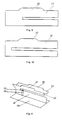
- the Y-antenna comprises a Y-shaped sheet structure 14 with two open notches 24 and 26 quarter wave resonant at different frequencies, each disposed in their V-shaped shanks and 10 and 12, respectively, of the Y, where the angle between these shanks is preferably 60° (fig 3 a-c).
- the feed unit consists, in the preferred embodiment, of a so-called semi-rigid coaxial cable 18.
- the more complex embodiment of the present invention includes an extra metal shank 22 which is shown in fig 4a and/or alternatively rectangular flarings along the upper edges of the shanks 10 and 12, as shown in fig 8a.
- the notches are of different lengths and thereby different resonance frequencies, they can function each in their of two adjacent frequency ranges.
- the directly fed notch functions in the frequency range of the second notch as a link in a transmission chain on transmission of energy to the second notch.
- the notch lengths and the position of the feed point 18-20 are trimmed until the adjacent frequency ranges obtain a well adapted overlap region which entails good impedance adaptation and good radiation properties within the total frequency band.
- the angle between the two shanks 10 and 12 of the V like the notch width, belong to those parameters which influence the coupling between the notches and should therefore be included in a fine tuning of the Y-antenna.
- the antenna is suitably mounted on a planar metal plate 16. In a carrier wave frequency of approx.
- the antenna can suitably have the following data: Antenna length 85,0 mm Antenna height 23,0 mm Notch length (26) 75,0 mm Notch length (24) 85,0 mm Notch height (26) 2,7 mm Notch height (24) 2,7 mm Shank height (10) 25,0 mm Shank length (10) 85,0 mm Shank height (12) 25,0 mm Shank length (12) 85,0 mm Shank width (10) 12,3 mm Shank width (12) 12,3 mm Base plate (16) length 85,0 mm Base plate (16) width 30,0 mm Extra shank total length 75,0 mm Shank edge tooth length (27) 32,0 mm Shank edge tooth height (27) 5,0 mm Shank edge tooth length (28) 40,0 mm Shank edge tooth height (28) 5,0 mm
- the dimensions of the antenna can be changed so that it suits other frequencies, eg. frequencies around 450 MHz or 1700 MHz.
Landscapes
- Engineering & Computer Science (AREA)
- Computer Networks & Wireless Communication (AREA)
- Waveguide Aerials (AREA)
- Details Of Aerials (AREA)
- Support Of Aerials (AREA)
Claims (4)
- Y-Antenne mit einem länglichen, Y-förmigen Metallteil und einer Bodenplatte aus Metall, die unter und im wesentlichen rechtwinklig zu dem vertikalen Schenkel des Y angebracht und galvanisch mit diesem Schenkel verbunden ist,
dadurch gekennzeichnet, daß die Y-förmige Metallstruktur zwei bevorzugt parallele Kerben (26, 24) umfaßt, die auf verschiedenen Frequenzen in Viertelwellenresonanz sind und an einem kurzen Ende offen sind, und daß die beiden Kerben jeweils in dem V-förmigen Schenkel (10, 12) des Y angeordnet sind eine gemeinsame Seite haben, die aus der Oberkante des vertikalen Abschnitts (14) des Y besteht. - Y-Antenne nach Anspruch 1,
dadurch gekennzeichnet, daß nur die Niederfrequenzkerbe mit der Speiseeinheit (18) gekoppelt ist, woraus sich ergibt, daß die andere Kerbe durch gegenseitige elektromagnetische Feldverbindung gespeist wird. - Y-Antenne nach Anspruch 2,
dadurch gekennzeichnet, daß ein zusätzlicher Metallschenkel (22) galvanisch mit dem kurzgeschlossenen kurzen Ende des direkt gespeisten V-Schenkels (10) verbunden ist, wonach der zusätzliche Schenkel knapp außerhalb der Ebene durch die kurzen Seiten der kurzgeschlossenen V-Schenkel weiter verläuft, bis er knapp über die Längsöffnung der V-Schenkel reicht, wo er derart gebogen ist, daß er etwa 70% der Längsöffnung der V-Schenkel abdeckt. - Y-Antenne nach einem der vorhergehenden Ansprüche,
dadurch gekennzeichnet, daß die Oberkanten der Blechschenkel (10 und 12) mit rechteckigen Aufweitungen (27 und 28) versehen sind.
Applications Claiming Priority (3)
| Application Number | Priority Date | Filing Date | Title |
|---|---|---|---|
| SE9203529 | 1992-11-20 | ||
| SE9203529A SE500477C2 (sv) | 1992-11-20 | 1992-11-20 | Y-antenn |
| PCT/SE1993/000969 WO1994013030A1 (en) | 1992-11-20 | 1993-11-15 | A y-antenna |
Publications (2)
| Publication Number | Publication Date |
|---|---|
| EP0670079A1 EP0670079A1 (de) | 1995-09-06 |
| EP0670079B1 true EP0670079B1 (de) | 1999-03-03 |
Family
ID=20387917
Family Applications (1)
| Application Number | Title | Priority Date | Filing Date |
|---|---|---|---|
| EP94901108A Expired - Lifetime EP0670079B1 (de) | 1992-11-20 | 1993-11-15 | Antenne in y-form |
Country Status (7)
| Country | Link |
|---|---|
| US (1) | US5600337A (de) |
| EP (1) | EP0670079B1 (de) |
| JP (1) | JP3262274B2 (de) |
| DE (1) | DE69323761T2 (de) |
| ES (1) | ES2131184T3 (de) |
| SE (1) | SE500477C2 (de) |
| WO (1) | WO1994013030A1 (de) |
Families Citing this family (17)
| Publication number | Priority date | Publication date | Assignee | Title |
|---|---|---|---|---|
| US5828345A (en) * | 1996-11-08 | 1998-10-27 | Northrop Grumman Corporation | Electrically short wide-band, wide-scan, slow wave dual notch radiator |
| US5977916A (en) * | 1997-05-09 | 1999-11-02 | Motorola, Inc. | Difference drive diversity antenna structure and method |
| US6043786A (en) * | 1997-05-09 | 2000-03-28 | Motorola, Inc. | Multi-band slot antenna structure and method |
| US6052094A (en) * | 1998-03-06 | 2000-04-18 | Kharadly; Mostafa Z. | Antenna system for millimeter wave length communication systems |
| SE513525C2 (sv) * | 1998-11-20 | 2000-09-25 | Smarteq Ab | En antennanordning |
| TW458392U (en) * | 2000-12-05 | 2001-10-01 | Hon Hai Prec Ind Co Ltd | Open slot antenna |
| JP3830358B2 (ja) * | 2001-03-23 | 2006-10-04 | 日立電線株式会社 | 平板アンテナおよびそれを備えた電気機器 |
| TW535329B (en) * | 2001-05-17 | 2003-06-01 | Acer Neweb Corp | Dual-band slot antenna |
| CN100481615C (zh) * | 2001-06-12 | 2009-04-22 | 启碁科技股份有限公司 | 双频开槽式天线 |
| TW591819B (en) * | 2001-08-29 | 2004-06-11 | Hon Hai Prec Ind Co Ltd | Slot antenna |
| JP3622959B2 (ja) * | 2001-11-09 | 2005-02-23 | 日立電線株式会社 | 平板アンテナの製造方法 |
| JP3656610B2 (ja) * | 2002-03-27 | 2005-06-08 | 日立電線株式会社 | 板状アンテナおよびそれを備えた電気機器 |
| JP3844717B2 (ja) * | 2002-07-19 | 2006-11-15 | ソニー・エリクソン・モバイルコミュニケーションズ株式会社 | アンテナ装置および携帯無線通信端末 |
| FR2970603A1 (fr) * | 2011-01-13 | 2012-07-20 | Thomson Licensing | Antenne directive imprimee de type fente et systeme mettant en reseau plusieurs antennes directives imprimees de type fente |
| US9653813B2 (en) | 2011-05-13 | 2017-05-16 | Google Technology Holdings LLC | Diagonally-driven antenna system and method |
| CN106935983A (zh) * | 2011-09-08 | 2017-07-07 | 英特尔公司 | 重叠的和交错的天线阵列 |
| US10641867B2 (en) | 2016-08-15 | 2020-05-05 | Magna Electronics Inc. | Vehicle radar system with shaped radar antennas |
Family Cites Families (3)
| Publication number | Priority date | Publication date | Assignee | Title |
|---|---|---|---|---|
| US2570824A (en) * | 1945-07-04 | 1951-10-09 | Rca Corp | Wide band antenna |
| US2996715A (en) * | 1955-03-10 | 1961-08-15 | Victor H Rumsey | Slot antenna with horn |
| US4843403A (en) * | 1987-07-29 | 1989-06-27 | Ball Corporation | Broadband notch antenna |
-
1992
- 1992-11-20 SE SE9203529A patent/SE500477C2/sv unknown
-
1993
- 1993-11-15 JP JP50758494A patent/JP3262274B2/ja not_active Expired - Fee Related
- 1993-11-15 US US08/428,070 patent/US5600337A/en not_active Expired - Fee Related
- 1993-11-15 WO PCT/SE1993/000969 patent/WO1994013030A1/en not_active Ceased
- 1993-11-15 ES ES94901108T patent/ES2131184T3/es not_active Expired - Lifetime
- 1993-11-15 DE DE69323761T patent/DE69323761T2/de not_active Expired - Fee Related
- 1993-11-15 EP EP94901108A patent/EP0670079B1/de not_active Expired - Lifetime
Also Published As
| Publication number | Publication date |
|---|---|
| SE500477C2 (sv) | 1994-07-04 |
| DE69323761T2 (de) | 1999-07-01 |
| ES2131184T3 (es) | 1999-07-16 |
| DE69323761D1 (de) | 1999-04-08 |
| SE9203529D0 (sv) | 1992-11-20 |
| EP0670079A1 (de) | 1995-09-06 |
| US5600337A (en) | 1997-02-04 |
| WO1994013030A1 (en) | 1994-06-09 |
| SE9203529L (sv) | 1994-05-21 |
| JP3262274B2 (ja) | 2002-03-04 |
| JPH08503580A (ja) | 1996-04-16 |
Similar Documents
| Publication | Publication Date | Title |
|---|---|---|
| EP0670079B1 (de) | Antenne in y-form | |
| US5710569A (en) | Antenna system having a choke reflector for minimizing sideward radiation | |
| US6195048B1 (en) | Multifrequency inverted F-type antenna | |
| KR100346599B1 (ko) | 무선 통신 단말용 내장 안테나 및 무선 통신 단말용 다이버시티 안테나 | |
| US6759990B2 (en) | Compact antenna with circular polarization | |
| EP0637094B1 (de) | Antenne für Mobilfunk | |
| DE69617550T2 (de) | Breitbandige doppel-C-förmige Streifenleiterantenne mit spaltgekoppelten parasitären Elementen | |
| US5420596A (en) | Quarter-wave gap-coupled tunable strip antenna | |
| US5185611A (en) | Compact antenna array for diversity applications | |
| EP1128467B1 (de) | Antennenvorrichtung | |
| KR20010075231A (ko) | 용량성으로 튜닝된 광대역 안테나 구조 | |
| EP1154513A1 (de) | Eingebaute antenne für drahtloses kommunikationsgerät | |
| US6195062B1 (en) | Printed circuit board-configured dipole array having matched impedance-coupled microstrip feed and parasitic elements for reducing sidelobes | |
| CA1213668A (en) | Two element low profile antenna | |
| JPH0669122B2 (ja) | 広帯域伝送線路アンテナ | |
| US5642120A (en) | Antenna device and wireless apparatus employing the same | |
| US6107967A (en) | Billboard antenna | |
| AU668748B2 (en) | Mobile radiotelephone having asymmetric radiation pattern | |
| JP3063826B2 (ja) | 多重周波数アンテナ | |
| US5001778A (en) | Portable radio receiver | |
| JPH0279602A (ja) | マイクロストリップアンテナ | |
| EP1667280B1 (de) | Ultrabreitbandige Antenne | |
| JPH09238019A (ja) | マイクロストリップアンテナ | |
| JPH01295505A (ja) | アンテナ装置 | |
| JPH02113706A (ja) | アンテナ装置 |
Legal Events
| Date | Code | Title | Description |
|---|---|---|---|
| PUAI | Public reference made under article 153(3) epc to a published international application that has entered the european phase |
Free format text: ORIGINAL CODE: 0009012 |
|
| 17P | Request for examination filed |
Effective date: 19950620 |
|
| AK | Designated contracting states |
Kind code of ref document: A1 Designated state(s): DE ES FR GB IT SE |
|
| GRAG | Despatch of communication of intention to grant |
Free format text: ORIGINAL CODE: EPIDOS AGRA |
|
| 17Q | First examination report despatched |
Effective date: 19980507 |
|
| GRAG | Despatch of communication of intention to grant |
Free format text: ORIGINAL CODE: EPIDOS AGRA |
|
| GRAH | Despatch of communication of intention to grant a patent |
Free format text: ORIGINAL CODE: EPIDOS IGRA |
|
| GRAH | Despatch of communication of intention to grant a patent |
Free format text: ORIGINAL CODE: EPIDOS IGRA |
|
| GRAA | (expected) grant |
Free format text: ORIGINAL CODE: 0009210 |
|
| AK | Designated contracting states |
Kind code of ref document: B1 Designated state(s): DE ES FR GB IT SE |
|
| REF | Corresponds to: |
Ref document number: 69323761 Country of ref document: DE Date of ref document: 19990408 |
|
| ET | Fr: translation filed | ||
| ITF | It: translation for a ep patent filed | ||
| REG | Reference to a national code |
Ref country code: ES Ref legal event code: FG2A Ref document number: 2131184 Country of ref document: ES Kind code of ref document: T3 |
|
| PLBE | No opposition filed within time limit |
Free format text: ORIGINAL CODE: 0009261 |
|
| STAA | Information on the status of an ep patent application or granted ep patent |
Free format text: STATUS: NO OPPOSITION FILED WITHIN TIME LIMIT |
|
| 26N | No opposition filed | ||
| PGFP | Annual fee paid to national office [announced via postgrant information from national office to epo] |
Ref country code: GB Payment date: 20001018 Year of fee payment: 8 |
|
| PGFP | Annual fee paid to national office [announced via postgrant information from national office to epo] |
Ref country code: FR Payment date: 20001019 Year of fee payment: 8 |
|
| PGFP | Annual fee paid to national office [announced via postgrant information from national office to epo] |
Ref country code: SE Payment date: 20001124 Year of fee payment: 8 |
|
| PGFP | Annual fee paid to national office [announced via postgrant information from national office to epo] |
Ref country code: DE Payment date: 20001128 Year of fee payment: 8 |
|
| PGFP | Annual fee paid to national office [announced via postgrant information from national office to epo] |
Ref country code: ES Payment date: 20011017 Year of fee payment: 9 |
|
| PG25 | Lapsed in a contracting state [announced via postgrant information from national office to epo] |
Ref country code: GB Free format text: LAPSE BECAUSE OF NON-PAYMENT OF DUE FEES Effective date: 20011115 |
|
| PG25 | Lapsed in a contracting state [announced via postgrant information from national office to epo] |
Ref country code: SE Free format text: LAPSE BECAUSE OF NON-PAYMENT OF DUE FEES Effective date: 20011116 |
|
| REG | Reference to a national code |
Ref country code: GB Ref legal event code: IF02 |
|
| EUG | Se: european patent has lapsed |
Ref document number: 94901108.4 |
|
| PG25 | Lapsed in a contracting state [announced via postgrant information from national office to epo] |
Ref country code: DE Free format text: LAPSE BECAUSE OF NON-PAYMENT OF DUE FEES Effective date: 20020702 |
|
| PG25 | Lapsed in a contracting state [announced via postgrant information from national office to epo] |
Ref country code: FR Free format text: LAPSE BECAUSE OF NON-PAYMENT OF DUE FEES Effective date: 20020730 |
|
| REG | Reference to a national code |
Ref country code: FR Ref legal event code: ST |
|
| REG | Reference to a national code |
Ref country code: FR Ref legal event code: ST |
|
| PG25 | Lapsed in a contracting state [announced via postgrant information from national office to epo] |
Ref country code: ES Free format text: LAPSE BECAUSE OF NON-PAYMENT OF DUE FEES Effective date: 20021116 |
|
| REG | Reference to a national code |
Ref country code: ES Ref legal event code: FD2A Effective date: 20031213 |
|
| PG25 | Lapsed in a contracting state [announced via postgrant information from national office to epo] |
Ref country code: IT Free format text: LAPSE BECAUSE OF NON-PAYMENT OF DUE FEES;WARNING: LAPSES OF ITALIAN PATENTS WITH EFFECTIVE DATE BEFORE 2007 MAY HAVE OCCURRED AT ANY TIME BEFORE 2007. THE CORRECT EFFECTIVE DATE MAY BE DIFFERENT FROM THE ONE RECORDED. Effective date: 20051115 |