EP0670097B1 - Verfahren zur verbindungsherstellung zwischen kommunikationsgeräten - Google Patents
Verfahren zur verbindungsherstellung zwischen kommunikationsgeräten Download PDFInfo
- Publication number
- EP0670097B1 EP0670097B1 EP94900171A EP94900171A EP0670097B1 EP 0670097 B1 EP0670097 B1 EP 0670097B1 EP 94900171 A EP94900171 A EP 94900171A EP 94900171 A EP94900171 A EP 94900171A EP 0670097 B1 EP0670097 B1 EP 0670097B1
- Authority
- EP
- European Patent Office
- Prior art keywords
- area
- location area
- communication
- definition
- location
- Prior art date
- Legal status (The legal status is an assumption and is not a legal conclusion. Google has not performed a legal analysis and makes no representation as to the accuracy of the status listed.)
- Expired - Lifetime
Links
- 238000000034 method Methods 0.000 title claims abstract description 43
- 230000001131 transforming effect Effects 0.000 claims description 13
- 101710171225 30S ribosomal protein S18 Proteins 0.000 claims description 7
- 101000637847 Homo sapiens Serine/threonine-protein kinase tousled-like 2 Proteins 0.000 claims description 7
- 102100032014 Serine/threonine-protein kinase tousled-like 2 Human genes 0.000 claims description 7
- 101710171217 30S ribosomal protein S15 Proteins 0.000 claims description 2
- 101710192523 30S ribosomal protein S9 Proteins 0.000 claims description 2
- 101000722833 Geobacillus stearothermophilus 30S ribosomal protein S16 Proteins 0.000 claims description 2
- 101710171187 30S ribosomal protein S10 Proteins 0.000 claims 1
- 230000011664 signaling Effects 0.000 description 9
- 101000637851 Homo sapiens Tolloid-like protein 1 Proteins 0.000 description 6
- 101000637850 Homo sapiens Tolloid-like protein 2 Proteins 0.000 description 6
- 102100031996 Tolloid-like protein 1 Human genes 0.000 description 6
- 102100031997 Tolloid-like protein 2 Human genes 0.000 description 6
- 101000637839 Homo sapiens Serine/threonine-protein kinase tousled-like 1 Proteins 0.000 description 4
- 102100032015 Serine/threonine-protein kinase tousled-like 1 Human genes 0.000 description 4
- 230000005540 biological transmission Effects 0.000 description 4
- 238000010586 diagram Methods 0.000 description 4
- 238000012423 maintenance Methods 0.000 description 4
- 101710171219 30S ribosomal protein S13 Proteins 0.000 description 1
- 230000001419 dependent effect Effects 0.000 description 1
- 230000006870 function Effects 0.000 description 1
Images


Classifications
-
- H—ELECTRICITY
- H04—ELECTRIC COMMUNICATION TECHNIQUE
- H04W—WIRELESS COMMUNICATION NETWORKS
- H04W68/00—User notification, e.g. alerting and paging, for incoming communication, change of service or the like
Definitions
- the invention relates to a method and a system for establishing a connection from a first communication device, connected to a communication network and having at least one identity, to one or several second communication devices, connected to the communication network and located in a limited location (paging) area, each of them having at least one identity.
- the operator of a communication system may change locaation areas of particular subscribers or subscriber groups by adjusting switches of a routing and controlling panel (dispatcher) connected to a communication exchange.
- a routing and controlling panel dispenser
- the communication exchange establishes a connection between the calling subscriber and the called subscriber or subscribers.
- a typical problem with communication systems containing mobile subscribers is how a calling subscriber may define the location area of a called subscriber or called subscribers, i.e. the area in which the called subscriber or the members of the group of called subscribers are searched for or paged, when a communication message shall be sent to them or a connection shall be established between them and the calling subscriber. It is necessary to define the location area for instance in a situation in which a calling subscriber wishes to establish a connection with a called subscriber or a group of called subscribers only if the called subscriber or subscribers are located in a predetermined area. For example, the calling subscriber wishes to speak with the called subscriber if this is in the neighbourhood, but he does not want to disturb the called subscriber if this is somewhere else, farther away.
- a definition of the location area is also necessary if the called subscribers with whom the calling subscriber wishes to speak belong to a larger group of called subscribers, but the calling subscriber wishes to speak only with those located in a predetermined location area, i.e. with a part of the group of called subscribers.
- An expansion of such a case is a situation in which the part of the group of called subscribers with whom the calling subscriber wishes to speak is moving, whereby it is natural that the calling subscriber frequently wishes to define the location area in which the very part of the group of called subscribers is searched for or paged with whom he wishes to speak.
- a situation of this kind may turn up in connection with radiotelephone systems, for instance, when the part of the group of called subscribers to be searched for moves for some reason; this may be the case, for instance, when all members of the part of the group follow some moving event, such as a moving sporting event.
- This is typical in radiotelephone systems, in which very many called subscribers use the same group identity.
- This situation is also possible in a fixed communication system, e.g. a PSTN (Public Switched Telephone Network), in which subscribers may plug in anywhere in the communication network, if only they inform their location to a database, thus enabling the communication network to route communication messages, phone calls, for subscribers to correct network addresses and so to correct subscribers.
- PSTN Public Switched Telephone Network
- a problem with such a prior art method and system for establishing a connection is that a calling subscriber or some other node of the communication network, such as a controller and/or dispatcher of a particular group of subscribers, is not capable of changing the location area in which a called subscriber or called subscribers are searched for or paged.
- the only possibility is then that the calling subscriber contacts separately a controlling centre existing in connection with the communication exchange.
- MML Man-Machine Language
- the operator may then, at the calling subscriber's command, change the location area in which the called subscriber or subscribers are searched for or paged.
- a procedure of this kind is naturally very cumbersome for the calling subscriber and the operator and consumes resources of the communication network.
- the controller and/or dispatcher of the group of subscribers has then no possibility of changing the location area directly, without any help from the operator of the respective communication system.
- Focus on Swedish Telecommunications 2/91 discloses a telecommunications system in which communication devices are called using location area identity and subscriber device identity. However, the subscriber device identities are also location area dependent.
- EP-A-0439628 describes a location registration method in a mobile radio communication system wherein location registration area codes are assigned to mobile subscribers and are updated when the subscriber moves into a location registration area to which the subscriber is not assigned.
- the object of the present invention is to give a calling subscriber or a network element other than the operation and maintenance centre existing in connection with the communication exchange a possibility of defining dynamically the location area in which a called subscriber or called subscribers are searched for or paged, when messages shall be sent to them or telephone channel connections shall be established with them.
- This novel method according to the invention for establishing a connection from a first communication device having at least one identity and being connected to a communication network comprising exchanges and/or base stations, to one or several second communication devices capable of moving to any location area of the communication network, the second communication devices being connected to the communication network, each of them having at least one identity that is independent of the current location of the communication device, is characterized in that the method comprises the following steps:
- This novel system according to the invention for establishing a connection between communication devices located in a limited location area is characterized in that the system comprises: a means for defining the location area and an identification for this area and for sending these definitions as a location area definition message to the communication network, a communication means for receiving a call setup message containing the location area identification sent by the first communication device to the communication network and the identity of one or several second communication devices, for sending the call setup message to one or several communication devices located in said defined location area and for establishing a connection between the first communication device and one or several second communication devices.
- the invention is based on the idea that the communication device of a calling subscriber is provided with a property by means of which the calling subscriber may define the location area in which a subscriber called by the calling subscriber is searched for and paged by means of which the calling subscriber may call the called subscriber in this defined location area. It is also possible to implement the location area definition function in some other part of the communication network, e.g. in a separate routing and/or controlling centre or at a control point (dispatcher).
- the location area may, of course, be defined in several manners. In this case according to the invention, the location area has been defined both by listing the identities of the base stations or communication exchanges located in the location area and by dividing the area covered by the communication systems into geographical parts indicated by the identities.
- An advantage of such a method and system for establishing a connection between communication devices located in a limited location area is that the system does establish connections from the calling subscriber to those called subscribers only with whom an entity which has defined the location area, e.g. the calling subscriber or the separate controller and/or dispatcher, wishes the connections to be established. Signalling capacity of the system is thus saved, because no unnecessary connections are established. Accordingly, this invention uses less communication resources, thus supporting fast call establishment, as the subscribers desire.
- the method and the system according to the invention are instead very suitable for defining location areas in such communication systems in which the location area of the subscribers moves continuously, because the definition of location area occurs flexibly and dynamically in this method and system.
- the location area may also be defined by somebody else than the operator of the communication network, because this definition may take place by means of a definition of those geographical areas in which a called subscriber/called subscribers are searched for or paged. Then the entity performing the definition does not need to know the addresses, location and number of the base stations or communication exchanges in the location area. Data of the base stations and communication exchanges selected for the location area then only exist in defining, transforming and memory means according to the invention and the operator has them. Accordingly, the subscriber of the communication network is thus given a user-friendly and flexible possibility of defining the location areas in which the called subscribers are searched for or paged.
- An additional advantage of the invention is that it may be utilized from any subscriber unit of the communication network, and therefore, no expensive and centralized separate operation and maintenance centre for defining the location area is needed, but any subscriber of the network may easily define the location area, if necessary.
- Figure 1 shows one application area of the invention, i.e. base stations BS1 to BS21 of a radio system and their coverage areas drawn with a thin circular or ellipsoidal line.
- Each base station BS1 to BS21 is naturally connected to some exchange device, a radio exchange, for example.
- Figure 2 shows a diagrammatic plan of some location area definition methods according to the invention in connection with the base stations BS1 to BS21 and their coverage areas.
- One location area definition method according to the invention is based on that an area covered by a communication network, especially a radio network, is divided as per the base stations BS1 to BS21 into areas in which the coverage areas of the base stations comprise the area covered by the communication network.
- the communication network may also be a fixed system based on wire connections, e.g. a PSTN, ISDN (Integrated Services Digital Network) or IN (Intelligent Network) system, in which the area covered by the communication network is divided into service areas of communication exchanges.
- the base stations BS1 to BS21 shown in Figure 2 may as well be communication exchanges and the coverage areas of the base stations may be service areas of the communication exchanges. Then the location area may be defined by listing identities of those communication exchanges in the service areas of which called subscribers shall be searched for or paged.
- a geographical area covered by a communication network is divided into typically polygonal, e.g. square parts marked with area indentifications. These parts may be marked with the area identifications for instance in the manner shown in Figure 2 by dividing the area covered by the communication network, based on square architecture, in such a way that rows of the square pattern are indicated by the same digit 1 to 8 and columns of the squares are indicated by the same character A, B, C, D, E, F.
- Each square may then be indicated unambiguously by marking it with a combination of one digit and one character, e.g. A1, D4 and F8.
- the identifications of those squares are listed which are supposed to form the location area, e.g. the identifications A1, D4 and F8.
- the location areas shown in Figure 2 may be defined in such a way that the identities of those base stations are listed which shall be contained in the location area. It is also possible to list only those base stations which are located at points of discontinuity of the geometrical shape of the desired location area, e.g. at points of vertical intersection of the area, or to list the midpoint and the radius of the area or the midpoint and one circumferential point of the area.
- a transforming means of the system then calculates the identities of the base stations of the whole geometrical shape from the identities of the base stations at the points of discontinuity of the geometrical shape, and the identities of all these base stations are used for the definition of the desired location area.
- Location areas may also be defined in such a way that the identities of those communication exchanges are listed which are located at the points of discontinuity of the geometrical shape of the desired location area, i.e. at points of vertical intersection of the area, or the midpoint and the radius of the area or the midpoint and one circumferential point of the area are listed.
- the transforming means of the system then calculates the identities of the communication exchanges of the whole geometrical shape from the identities of the communication exchanges at the points of discontinuity of the geometrical shape, and the identities of all these communication exchanges are used for the definition of the desired location area.
- the location areas may be defined by means of those parts of the area covered by the communication network which are marked with area identifications in such a way that the area identifications of the parts marked with area identifications and located at points of discontinuity of the geometrical shape of the desired location area, e.g. at points of vertical intersection of the area, are listed or the midpoint and the radius of the area or the midpoint and one circumferential point of the area are listed.
- the transforming means of the system then calculates all area identities of the whole geometrical shape from the area identifications of the points of discontinuity of the geometrical shape. All these area identifications are utilized for the definition of the desired location area, when the transforming means transforms the area identifications into identities of those base stations or communication exchanges in the location or service area of which the desired location area is located.
- Figure 2 illustrates a selection of a square location area, performed by the user by means of area identifications.
- the user has defined the location area by selecting area identifications C4, F4, C7 and F7 as points of vertical intersection for the square geometrical shape.
- the system of the invention transforms the area identifications of the geometrical shape to base stations or communication exchanges, the base stations BS10 to BS15 and BS18 to BS21 are selected in the first case. If the user has defined that the location area consists only of the edge area of the geometrical shape, the base station BS14 is excluded from the location area.
- Figure 3 shows a plurality of geometrical shapes used in the location area definition method according to the invention.
- Detail figure 301 shows a straight line or a band, which the user of the communication system of the invention may define as location area by giving area identifications of the initial point A and the final point B of the band or the identities of the base stations or communication exchanges at the same geographical location.
- detail figure 302 shows a triangle C, D, E, which the user may define as location area by giving the area identifications of the points of vertical intersection of the triangle or the identities of the base stations or communication exchanges at the same geographical location.
- Detail figure 303 shows a quadrangle F, G, H, I, which the user may analogically define as location area by applying the manners described in connection with the explanation of the figures 301 and 302.
- Detail figure 304 shows a polygon J, K, L, M, N, which the user further may analogically define as location area by applying the manners described in connection with the explanation of the figures 301 and 302.
- Detail figure 305 shows a circle, which the user may define as location area by giving an area identification of the midpoint P0 of the circle or the identity of the base station or communication exchange at the same geographical location as well as the radius R of the circle.
- Detail figure 306 shows a circle, which the user may define as location area by giving the area identification of the midpoint P0 of the circle or the identity of the base station or communication exchange at the same geographical location as well as an area identification of a point P1 at the circumference of the circle or the identity of the corresponding base station or communication exchange.
- the user may define whether the location area shall contain the areas contained in these geometrical shapes shown in Figure 3 or only the edge areas of the geometrical shapes, by defining a filling degree of the location area in a manner to be shown later in Figure 7.
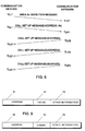
- FIG 4 shows a signalling diagram of a transmission of signalling messages used for establishing a connection in a radio system.
- a radio station MS1 sends a location area Ak definition message according to the invention, which message will be described in more detail in connection with the explanation of the figures 7, 9 and 14.
- the location area definition message could also be sent by any other radio station MS2 to MS9 or by some other part of the radio system, e.g. a separate location area definition means connected to some network element.
- the base station BS1 After the base station BS1 has received the location area definition message, the base station BS1 sends an information of the definition of the location area to a memory means shown in Figure 13 and located in the exchange device of the radio system shown in Figure 8, which memory means stores the definition of the location area in its memory.
- the location area definition method described here is only one method of implementing the definition of the location area.
- the first radio station MS1 sends a call setup message, containing, firstly, the identity or address of that second or those second radio stations with whom the radio station MS1 wishes to establish a connection, and secondly, the identification of that location area in which the radio station MS1 wishes this/these second radio station/stations to be searched for or paged.
- the exchange device of the radio system commands the base stations BS2, BS3, BS4 located in partial areas of the defined location area to send the call setup messages to the radio telephones MS2 to MS4, MS5 to MS8 and MS9 in the coverage areas of these base stations.
- call setup messages then contain either the addresses or identities of the current subscribers or the address or identity of that group of subscribers to which these subscribers belong.
- the reader has noticed that the definition message and the call setup messages described above have been sent on the radio path between the base stations and the radiotelephones in their coverage areas.
- FIG. 5 shows a signalling diagram of a transmission of signalling messages used for establishing a connection in a communication system.
- a communication device TLL1 sends a location area Ak definition message to a communication exchange TLK1.
- Some examples of the location area definition message to be sent will be presented in connection with the explanation of the figures 7, 9 and 14.
- the communication exchange TLK1 stores the definition of the location area in the memory means contained in the communication exchange shown in Figure 12, which memory means will be illustrated in more detail in Figure 13.
- some communication device in this figure the communication device TLL1, sends a call setup message containing, firstly, the identity or address of that/those second communication device/devices TLL2 to TLL4 with whom the communication device TLL1 wishes to establish a connection, and secondly, the identification Ak of that location area in which the communication device TLL1 wishes these second communication devices TLL2 to TLL4 to be searched for or paged.
- Some communication exchange of the communication network in this case the communication exchange TLK1, receives this call setup message and transmits its content to communication exchanges TLK2, TLK3, TLK4 located in the location area Ak defined by the first communication device TLL1 in its location area definition message.
- these communication exchanges TLK2, TLK3, TLK4 located in the location area send to the communication devices TLL2, TLL3, TLL4, located in their own location area and mentioned in the call setup message sent by the first communication device TLL1, call setup messages provided with the addresses of these communication devices TLL2, TLL3, TLL4 or with the address of that subscriber group to which all these communication devices belong.
- connections are established between each communication exchange TLK2, TLK3, TLK4 and the respective communication devices TLL2, TLL3, TLL4. It is understandable that the communication devices TLL2, TLL3, TLL4 with which connections are established may be one or several in number.
- the communication system illustrated in connection with this Figure 5 may be either a radio system, the radio path and base stations of which have not been illustrated for the sake of simplicity, or a communication system based on wire-line connections, in which system mobile subscribers are possible, however.
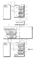
- Figure 6 shows one embodiment of the system according to the invention for defining the location area and/or for establishing a connection in the radio network.
- the figure shows a first user device 1 provided with a user interface between the subscriber and the communication network.
- the user device 1 is joined by means of a connecting means 2, typically a cable, to a radio unit 3.
- the radio unit and the user device may naturally be implemented as one unit.
- the base station and the exchange device of the radio system may be implemented as one unit.
- a device 9 may be joined to the exchange device of the radio system over a connection 8, typically a cable.
- a second user device 18 which may be similar to the first user device 1 joined to the radio unit 3.
- the second user device 18 and the device 9 joined over the cable may naturally be implemented as one unit.
- the first user device 1 contains a means 10 for defining the location area.
- a similar location area definition means 10 is included in the second user device 18.
- the user of the system may define the location area in which he wishes subscribers having a particular identification to be searched for or paged.
- the user forms a location area definition message shown in Figure 7, i.e. gives the address of that/those communication device/devices the location area of which he wishes to define.
- the address may be either some address of the user or some address of another user. In the latter case, depending on the system, a separately granted permission may be needed therefor.
- this address is positioned in field 71, radio address.
- the area definition of field 72 comprises a definition of the geometrical shape of the area by means of the identities of those geographical parts, base stations or communication exchanges in the area of which the points of discontinuity of the geometrical shape of the location area, the points of vertical intersection of the area, the midpoint and the radius of the area or the midpoint and the circumferential point of the area are located.
- the user defines field 73 of the location area definition message, filling degree of the area, which field indicates whether the location area shall contain only those parts marked with area identifications, base station identities or communication exchange identities which line the geometrical shape or also the parts, base stations or communication exchanges marked with area identifications which are located within the geometrical shape.
- the user gives the location area by the defining means an identification he desires to give, which identification is located in field 74 of Figure 7, area identification.
- the radio unit 3 sends the location area definition message shown in Figure 7 along a radio path to a base station 5, which sends the message further to the exchange device 7 of the radio system.
- the location area definition message is sent along a wire connection 8 to the exchange device 7 of the radio system.
- the exchange device 7 transmits the location area definition message to a transforming means 11.
- the transforming means transforms the location area definition into identities of such base stations or communication exchanges the service areas of which essentially cover the location area.
- the first radio station when one first radio station of the radio system wishes to establish a connection with a second radio station or a group of radio stations in this defined location area, the first radio station sends in the manner shown in Figure 4 a call setup message containing the location area identification and the identity of the second radio station or group of radio stations to a base station, which transmits the call setup message to a call setup means 13 of the exchange device 7 of the radio system, which setup means asks the memory means 12 for the identities of the base stations corresponding to the location area identification.
- the call setup means 13 establishes connections between the first radio station and that/those radio station/stations which are located in a location area corresponding to the location area identification and which had in the original call setup message the identity of the second radio station or group of radio stations.
- Figure 7 shows one embodiment of a radio path message used by the method and system of the invention, which message is sent by the entity defining the location area, for example a user device joined to a radio station or a user device joined to a wire-connected device, to the transforming or memory means of the exchange device of the communication exchange or the radio system.
- Field 71 of the message comprises the identity of that radio or communication device or group the location area of which is in question, i.e. for which radio or communication devices the location area is supposed to be defined.
- the message further comprises field 72 for area definition, containing a definition of the geometrical shape of the area by means of the identities of those geographical parts, base stations or communication exchanges in the area of which the points of discontinuity of the geometrical shape of the location area, the points of vertical intersection of the area, the midpoint and the radius of the area or the midpoint and the circumferential point of the area are located.
- Field 73 filling degree of the area, defines whether the location area shall contain only those parts marked with area identifications, base station identities or communication exchange identities which line the geometrical shape or also those parts, base stations or communication exchanges marked with area identifications which are located within the geometrical shape.
- Field 74, area identification defines the identification of the location area. This identification may be defined by the entity defining the location area.
- Figure 8 shows one embodiment of the system according to the invention for defining the location area and/or for establishing a connection in the radio network.
- the solution of Figure 8 is similar to that of Figure 6, except that the transforming means 11 has been removed from the exchange device of the radio system to the user device 1 and 18 in Figure 8.
- the location area definition message shown in Figure 9 and to be sent from the user device to the exchange device of the radio system is different from the message shown in Figure 7.
- the message shown in Figure 9 lacks the area definition field 72 and the field 73, filling degree of the area.
- These fields have been replaced by an identification field 92 according to Figure 9, specifying the base stations or the communication exchanges, in which field one bit of a binary digit presented identifies one base station or communication exchange.
- Field 93 of Figure 9, other information, may contain the location area identification.
- the location area definition message is sent from the transforming means 11 of the user device 1 or 18 to the memory means 12 of the exchange device 7 of the radio system, either along the radio path 4 or over the base station 5 or along the wire connection 8.
- the content of field 92 of the definition message ( Figure 9) is stored in the memory means 12.
- a call establishment takes place in this embodiment in the same way as described in connection with Figure 6.
- Figure 10 shows one embodiment of the system according to the invention for establishing a connection in a radio network.
- This embodiment is similar to that of Figure 8, except that the memory means 12 in the exchange device of the radio system is located in the user device 1 or 18 in Figure 8.
- the first radio station or communication device here the user device, wishes to establish a connection with the second radio station or communication device, it has to include in the call setup message also the definition of the location area, i.e. the identities of those base stations or communication exchanges in the area of which the first radio station wishes called subscribers to be searched for or paged.
- Such a definition of base stations and communication exchanges may correspond to the field 92 of Figure 9.
- Figure 11 shows one embodiment of the system according to the invention for establishing a connection in a radio network.
- the location area definition means 10, the transforming means 11 and the memory means 12 are located in the radio unit 3 or/and in the wire-connected device 9, instead of some of them being located in the user device 1 or 18 or in the exchange device 7 of the radio system.
- the call setup message to be sent from the radio unit or the wire-connected device is similar to that illustrated in Figure 10.
- Figure 12 shows one embodiment of the system according to the invention for defining the location area and/or for establishing a connection in a fixed communication network based on wire connections, e.g. PSTN, ISDN or IN.
- Figure 12 shows a first user device 101, 118 provided with a user interface to the communication network.
- the user device 101, 118 is joined by a connecting means 102, 119, typically a cable, to a wire-connected device 103, 109.
- the wire-connected device and the user device may naturally be implemented as one unit.
- To the communication exchange may additionally be joined the wire-connected device 109 over a connection 108, typically a cable, to which device 109 is joined further, by a connecting means 119, the second user device 118, which may be similar to the first user device 101 joined to the wire-connected device 103.
- a location area definition means 110 has been connected to the first user device 101.
- a corresponding location area definition means 110 has been connected to the second user device 118.
- the user of the system may define the location area in which the user wishes subscribers provided with a particular identity to be searched for or paged.
- the definition means the user forms a location area definition message as described in Figure 7, i.e. the user gives the address of that communication device or those communication devices with which the user wishes to establish a connection in the defined location area.
- the definition of the location area is described in more detail in connection with the specification of Figure 6.
- Figure 13 shows the memory hierarchy of the memory means used by the method and system of the invention.
- an identification 202 of the defined location area and identities 203 of the base stations or the communication exchanges located in the defined location area correspond to user identities 201.
- Figure 14 shows detailed examples of location area definition messages according to the invention.
- Fields 301, 302, 303 describe a location area definition message similar to that of Figure 9.
- fields 304, 305, 306, 307 describe a location area definition message illustrated in Figure 7.
- Fields 308 or 309 and 310 describe an alternative content of the fields 302 and 305.
- the area may be defined alternatively by defining the identities of the base stations or the communication exchanges or the identifications of the desired geographical areas, as described in field 308, or by presenting the number of parameters to be used at first in field 309, number of parameters, as well as the actual area definition parameters 310, being typically identifications of those geographical areas which are supposed to be defined as location area.
- Field 309, number of parameters presents the number of the points of discontinuity of the geometrical shape typically to be selected to constitute the location area.
Landscapes
- Engineering & Computer Science (AREA)
- Computer Networks & Wireless Communication (AREA)
- Signal Processing (AREA)
- Mobile Radio Communication Systems (AREA)
- Communication Control (AREA)
- Computer And Data Communications (AREA)
- Data Exchanges In Wide-Area Networks (AREA)
Claims (14)
- Verfahren zum Herstellen einer Verbindung von einer ersten Kommunikationseinrichtung (MS1, 1, 18), die mindestens eine Identität hat und mit einem Kommunikationsnetz verbunden ist, das Vermittlungsstellen und/oder Basisstationen aufweist, zu einer oder mehreren zweiten Kommunikationseinrichtungen (MS2 bis MS9), die in der Lage sind, sich in irgendein Standortgebiet (Ak) des Kommunikationsnetzes zu bewegen, wobei die zweiten Kommunikationseinrichtungen (MS2 bis MS9) mit dem Kommunikationsnetz verbunden sind und jede von ihnen mindestens eine Identität hat, die unabhängig von dem aktuellen Standort der Kommunikationseinrichtung ist,
dadurch gekennzeichnet,
daß das Verfahren folgende Schritte aufweist:Definieren (10) des Standortgebietes (Ak) für die zweiten Kommunikationseinrichtungen und einer Identifizierung für das Standortgebiet (Ak),die erste Kommunikationseinrichtung (MS1, 1, 18) sendet dem Kommunikationsnetz eine Nachricht, die die Identifizierung des Standortgebietes (Ak) und die Identität von einer oder mehreren zweiten Kommunikationseinrichtungen enthält,das Kommunikationsnetz fragt ab und/oder ruft an mindestens eine zweite Kommunikationseinrichtung (MS2 bis MS9), die mit dieser Identität ausgestattet ist nur in dem Standortgebiet, das durch die Identifizierung des Standortgebietes (Ak) definiert ist. - Verfahren nach Anspruch 1,
dadurch gekennzeichnet,
daß das Standortgebiet von dem Kommunikationsoperator und/oder dem Benutzer der Kommunikationseinrichtung definiert wird. - Verfahren nach Anspruch 2,
dadurch gekennzeichnet,
daß das Standortgebiet definiert wird durch Auflisten der Identitäten der Basisstationen (BS2 bis BS4), die in dem Standortgebiet enthalten sind, durch Auflisten der Identitäten der Kommunikationsvermittlungsstellen (TLK2 bis TLK4), die in dem Standortgebiet enthalten sind, oder durch das Unterteilen des geographischen Gebietes, das durch das Kommunikationsnetz abgedeckt ist, in typischerweise polygonale Bereiche, die mit Gebietsidentifizierungen markiert sind, und durch Auflisten der Gebietsidentifizierungen der Bereiche, die in dem Standortgebiet enthalten sind. - Verfahren nach Anspruch 3,
dadurch gekennzeichnet,
daß der Operator des Kommunikationsnetzes oder der Benutzer der Kommunikationseinrichtung das Standortgebiet in einem ersten Format definiert, aus dem es automatisch in Identitäten von derartigen Basisstationen (BS2 bis BS4), Kommunikationsvermittlungsstellen (TLK2 bis TLK4) oder Gebieten transformiert wird, deren Versorgungsbereiche das Standortgebiet abdecken. - Verfahren nach Anspruch 4,
dadurch gekennzeichnet,
daß das erste Format eine oder mehrere Identitäten (71) von einer oder mehreren Kommunikationseinrichtungen, den Typ (309) des Gebietes, den Füllungsgrad (73) des Gebietes, die Gebietsdefinition (72) und die Identifizierung (74) des Standortgebietes enthält. - Verfahren nach Anspruch 3 oder 5,
dadurch gekennzeichnet,
daß die Gebietsdefinition (72) eine Definition der geometrischen Form des Gebietes mittels der Identitäten von denjenigen geographischen Bereichen, Basisstationen (BS2 bis BS4) oder Kommunikationsvermittlungsstellen (TLK2 bis TLK4) aufweist, in deren Gebiet sich Unstetigkeitspunkte (A bis M) der geometrischen Form des Standortgebietes, vertikale Schnittpunkte (C bis M) des Gebietes, Mittelpunkt (P0) und Radius (R) des Gebietes oder Mittelpunkt (P0) und Umfangspunkt (P1) des Gebietes befinden. - Verfahren nach Anspruch 3 und 5,
dadurch gekennzeichnet,
daß der Füllungsgrad (73) des Gebietes definiert, ob das Standortgebiet nur diejenigen Bereiche enthalten soll, die mit Gebietsidentifizierungen, Identitäten (BS10 bis BS13, BS15, BS18 bis BS21) von Basisstationen oder Identitäten von Kommunikationsvermittlungsstellen markiert sind, die die geometrische Form zeichnen, oder auch diejenigen Bereiche, Basisstationen (BS14) oder Kommunikationsvermittlungsstellen, die mit Gebietsidentifizierungen markiert sind und die sich innerhalb der geometrischen Form befinden. - Verfahren nach Anspruch 6 oder 7,
dadurch gekennzeichnet,
daß die geometrische Form eine Gerade (301), ein Dreieck (302), ein Vieleck (304) oder ein Kreis (305, 306) ist. - Verfahren nach Anspruch 5, 7 oder 8,
dadurch gekennzeichnet,
daß die Gebietsdefinition zusätzlich eine Definition der Anzahl (309) der Unstetigkeitspunkte der geometrischen Form des Gebietes aufweist. - System zum Herstellen einer Verbindung zwischen einer ersten Kommunikationseinrichtung (1, 18), die mit einem Kommunikationsnetz verbunden ist, und einer oder mehreren zweiten Kommunikationseinrichtungen, die mit dem Kommunikationsnetz verbunden sind und sich in einem begrenzten Standort(Anruf)-Gebiet befinden, wobei jede von ihnen mindestens eine Identität hat,
dadurch gekennzeichnet,
daß das System folgendes aufweist:eine Einrichtung (10) zum Definieren des Standortgebietes und einer Identifizierung für dieses Gebiet und zum Senden dieser Definitionen als Standortgebiets-Definitionsnachricht an das Kommunikationsnetz,eine Kommunikationseinrichtung (7) zum Empfangen (14) einer Verbindungsaufbaunachricht, die die Identifizierung des Standortgebietes, das von der ersten Kommunikationseinrichtung (MS1) an das Kommunikationsnetz gesendet worden ist, und die Identität von einer oder mehreren zweiten Kommunikationseinrichtungen (MS2 bis MS9) enthält, zum Senden (13) der Verbindungsaufbaunachricht an eine oder mehrere Kommunikationseinrichtungen (MS2 bis MS9), die sich in dem definierten Standortgebiet befinden, und zum Herstellen einer Verbindung zwischen der ersten (MS1) und einer oder mehreren zweiten Kommunikationseinrichtungen (MS2 bis MS9). - System nach Anspruch 10,
dadurch gekennzeichnet,
daß es weiterhin eine Speichereinrichtung (12) zum Speichern der Standortgebietsdefinition (203) und der Standortgebietsidentifizierung (202) aufweist. - System nach Anspruch 10,
dadurch gekennzeichnet,
daß die Kommunikationsvermittlungsstelle (7) weiterhin folgendes aufweist:eine Verbindungsaufbaueinrichtung (13) zum Herstellen von Verbindungen zwischen den ersten (MS1) und einer oder mehreren zweiten Kommunikationseinrichtungen (MS2 bis MS9),eine Speichereinrichtung (12) zum Speichern der Definition des Standortgebietes,eine Einrichtung (14) zum Empfangen von StandortgebietsDefinitionsnachrichten und Verbindungsaufbaunachrichten, die von der ersten Kommunikationseinrichtung (MS1) gesendet worden sind, und zum Übertragen dieser Verbindungsaufbaunachrichten an die Verbindungsaufbaueinrichtung (13) und zum Übertragen der Standortgebiets-Definitionsnachrichten an die Speichereinrichtung (12). - System nach Anspruch 11,
dadurch gekennzeichnet,
daß die Einrichtung (12) zur Definition des Standortgebietes und deren Identifizierung mit der Kommunikationseinrichtung (1, 18) oder der Kommunikationsvermittlungsstelle (7) verbunden ist. - System nach Anspruch 10, 11, 12 oder 13,
dadurch gekennzeichnet,
daß es eine Transformationseinrichtung (11) zum Transformieren der Definition des Standortgebietes in Identitäten von solchen Basisstationen (BS2 bis BS4) oder Kommunikationsvermittlungsstellen (TLK2 bis TLK4) aufweist, dessen Versorgungsbereiche im wesentlichen das Standortgebiet abdecken.
Applications Claiming Priority (3)
| Application Number | Priority Date | Filing Date | Title |
|---|---|---|---|
| FI925236A FI96156C (fi) | 1992-11-18 | 1992-11-18 | Menetelmä ja järjestelmä tietoliikenneyhteyden muodostamiseksi rajoitetulla kutsualueella sijaitseville tietoliikennelaitteille |
| FI925236 | 1992-11-18 | ||
| PCT/FI1993/000486 WO1994011997A1 (en) | 1992-11-18 | 1993-11-17 | Method for establishing connection between communication devices |
Publications (2)
| Publication Number | Publication Date |
|---|---|
| EP0670097A1 EP0670097A1 (de) | 1995-09-06 |
| EP0670097B1 true EP0670097B1 (de) | 1998-01-21 |
Family
ID=8536241
Family Applications (1)
| Application Number | Title | Priority Date | Filing Date |
|---|---|---|---|
| EP94900171A Expired - Lifetime EP0670097B1 (de) | 1992-11-18 | 1993-11-17 | Verfahren zur verbindungsherstellung zwischen kommunikationsgeräten |
Country Status (8)
| Country | Link |
|---|---|
| US (1) | US5633913A (de) |
| EP (1) | EP0670097B1 (de) |
| JP (1) | JP3464483B2 (de) |
| AT (1) | ATE162678T1 (de) |
| AU (1) | AU674362B2 (de) |
| DE (1) | DE69316648T2 (de) |
| FI (1) | FI96156C (de) |
| WO (1) | WO1994011997A1 (de) |
Families Citing this family (25)
| Publication number | Priority date | Publication date | Assignee | Title |
|---|---|---|---|---|
| FI94994C (fi) * | 1992-10-19 | 1995-11-27 | Nokia Telecommunications Oy | Hajapääsymenetelmä radiojärjestelmässä |
| DE19605632A1 (de) * | 1996-02-15 | 1997-08-21 | Aeg Mobile Communication | Verfahren zur Übermittlung eines Sammelrufs an Mobilteilnehmer in einem GSM-Netz |
| US6052591A (en) * | 1996-08-19 | 2000-04-18 | Ericsson Inc. | Broadcasting messages to mobile stations within a geographic area |
| FI105638B (fi) * | 1997-05-14 | 2000-09-15 | Nokia Networks Oy | Menetelmä solukkoradiojärjestelmän eri osien kapasiteettitarpeen arvioimiseksi |
| US6115605A (en) | 1997-08-29 | 2000-09-05 | Ppm, Inc. | Communication system and device using dynamic receiver addressing |
| US6026297A (en) * | 1997-09-17 | 2000-02-15 | Telefonaktiebolaget Lm Ericsson | Contemporaneous connectivity to multiple piconets |
| US6400942B1 (en) | 1998-11-09 | 2002-06-04 | Telefonaktie Bolaget Lm Ericsson (Publ) | Method and system for broadcasting large short messages |
| SE519308C2 (sv) | 1998-12-15 | 2003-02-11 | Ericsson Telefon Ab L M | Cellulärt mobilkommunikationssystem och metod i sådant system |
| US6490443B1 (en) * | 1999-09-02 | 2002-12-03 | Automated Business Companies | Communication and proximity authorization systems |
| DE19953640A1 (de) * | 1999-11-09 | 2001-05-10 | Deutsche Telekom Ag | Verfahren zum telekommunikationsgestützten Schutz und Auffinden von Lebewesen |
| WO2001047303A1 (en) * | 1999-12-20 | 2001-06-28 | Ericsson Inc. | Fleet management using mobile working unit positioning and wireless communications systems |
| US20020091843A1 (en) * | 1999-12-21 | 2002-07-11 | Vaid Rahul R. | Wireless network adapter |
| US6414635B1 (en) * | 2000-10-23 | 2002-07-02 | Wayport, Inc. | Geographic-based communication service system with more precise determination of a user's known geographic location |
| US6937861B2 (en) * | 2001-02-13 | 2005-08-30 | Telefonaktiebolaget Lm Ericsson (Publ) | Connection management for dual mode access terminals in a radio network |
| US20050272429A1 (en) * | 2002-06-28 | 2005-12-08 | Rod Walsh | Approximating cell geometry in a cellular transmission system |
| EP1662824A4 (de) * | 2003-06-20 | 2010-05-26 | Ntt Docomo Inc | Steuervorrichtung und mobiles endgerät |
| US7660872B2 (en) * | 2005-05-17 | 2010-02-09 | International Business Machines Corporation | Managing location information for a group of users |
| KR20090086428A (ko) | 2006-11-02 | 2009-08-12 | 디지포니카 (인터내셔널) 리미티드 | VoIP 통신을 위한 라우팅 메세지 생성 |
| US8422507B2 (en) | 2006-11-29 | 2013-04-16 | Digifonica (International) Limited | Intercepting voice over IP communications and other data communications |
| US8537805B2 (en) * | 2007-03-26 | 2013-09-17 | Digifonica (International) Limited | Emergency assistance calling for voice over IP communications systems |
| CA2732148C (en) * | 2008-07-28 | 2018-06-05 | Digifonica (International) Limited | Mobile gateway |
| US8587017B2 (en) | 2009-07-05 | 2013-11-19 | Industrial Technology Research Institute | Light emitting device and method of fabricating a light emitting device |
| PL2478678T3 (pl) | 2009-09-17 | 2016-05-31 | Digifonica Int Ltd | Bezprzerwowe przesyłanie transmisji protokołu internetowego podczas zmian punktów końcowych |
| CN102668506B (zh) * | 2009-11-27 | 2017-04-26 | 瑞典爱立信有限公司 | 在通信网络中传递消息 |
| US9241330B2 (en) | 2012-04-26 | 2016-01-19 | Industrial Technology Research Institute | Resource management method and apparatuses for device to device communications |
Family Cites Families (12)
| Publication number | Priority date | Publication date | Assignee | Title |
|---|---|---|---|---|
| US3818145A (en) * | 1972-07-19 | 1974-06-18 | United Eng Corp | Radio paging system |
| US4154988A (en) * | 1977-10-21 | 1979-05-15 | Wescom Switching, Inc. | Method and means for accessing program memory of a common control telecommunications switching system |
| US4737978A (en) * | 1986-10-31 | 1988-04-12 | Motorola, Inc. | Networked cellular radiotelephone systems |
| EP0283683B1 (de) * | 1987-03-20 | 1994-01-12 | Hitachi, Ltd. | Tragbares schnurloses Kommunikationssystem und Verfahren |
| US5077830A (en) * | 1988-02-17 | 1991-12-31 | Indesys, Inc. | Method and apparatus to selectively address recipients and recover missing messages on a broadcast distribution network |
| US4878051A (en) * | 1988-02-22 | 1989-10-31 | Telefind Corp. | Paging system with commands for changing functionality of a paging receiver |
| JP2545466B2 (ja) * | 1989-08-24 | 1996-10-16 | 日本電信電話株式会社 | 移動通信位置登録方法 |
| US5153902A (en) * | 1990-04-27 | 1992-10-06 | Telefonaktiebolaget L M Ericsson | Multi-exchange paging system for locating a mobile telephone in a wide area telephone network |
| CA2076434C (en) * | 1991-10-09 | 1996-07-02 | Gary Joe Grimes | Incoming communications forwarding technique utilizing a called party location indicator |
| US5396543A (en) * | 1991-11-27 | 1995-03-07 | At&T Corp. | Signaling arrangements in a cellular mobile telecommunications switching system |
| US5390234A (en) * | 1992-04-20 | 1995-02-14 | International Business Machines Corporation | Dynamic tracking of mobile stations in wireless networks |
| US5387905A (en) * | 1992-10-05 | 1995-02-07 | Motorola, Inc. | Mutli-site group dispatch call method |
-
1992
- 1992-11-18 FI FI925236A patent/FI96156C/fi not_active IP Right Cessation
-
1993
- 1993-11-17 AT AT94900171T patent/ATE162678T1/de active
- 1993-11-17 JP JP51176794A patent/JP3464483B2/ja not_active Expired - Lifetime
- 1993-11-17 WO PCT/FI1993/000486 patent/WO1994011997A1/en not_active Ceased
- 1993-11-17 DE DE69316648T patent/DE69316648T2/de not_active Expired - Lifetime
- 1993-11-17 US US08/436,185 patent/US5633913A/en not_active Expired - Lifetime
- 1993-11-17 EP EP94900171A patent/EP0670097B1/de not_active Expired - Lifetime
- 1993-11-17 AU AU54673/94A patent/AU674362B2/en not_active Ceased
Non-Patent Citations (1)
| Title |
|---|
| TEKETSUGU et al., "Holonic Location Registration/Paging Procedure in Microcellular Systems", page 1652 - page 1659. * |
Also Published As
| Publication number | Publication date |
|---|---|
| FI96156C (fi) | 1996-05-10 |
| AU674362B2 (en) | 1996-12-19 |
| FI925236A0 (fi) | 1992-11-18 |
| US5633913A (en) | 1997-05-27 |
| DE69316648T2 (de) | 1998-07-02 |
| ATE162678T1 (de) | 1998-02-15 |
| JPH08503112A (ja) | 1996-04-02 |
| JP3464483B2 (ja) | 2003-11-10 |
| AU5467394A (en) | 1994-06-08 |
| FI925236L (fi) | 1994-05-19 |
| DE69316648D1 (de) | 1998-02-26 |
| FI96156B (fi) | 1996-01-31 |
| WO1994011997A1 (en) | 1994-05-26 |
| EP0670097A1 (de) | 1995-09-06 |
Similar Documents
| Publication | Publication Date | Title |
|---|---|---|
| EP0670097B1 (de) | Verfahren zur verbindungsherstellung zwischen kommunikationsgeräten | |
| EP0862346B1 (de) | Zellpriorität in einem zellularen Funksystem | |
| CN1243647B (zh) | 用于移动通信系统中的本地化特定业务的方法和设备 | |
| EP1135918B1 (de) | Verfahren und system zum dynamischen umleiten von leitungsgebundener anrufzustellung | |
| US6192115B1 (en) | Obtaining information about a called telecommunications party | |
| US5724658A (en) | Call routing to wireless roamers in mobile telecommunication systems | |
| AU713449B2 (en) | Intelligent mobile station for a cellular telecommunications network | |
| MY130505A (en) | Providing individual subscriber services in a cellular mobile communications network | |
| AU7740998A (en) | Use of ISDN to provide wireless office environment connection to the public land mobile network | |
| CA2313142A1 (en) | Method and arrangement in a communication network | |
| CN1223774A (zh) | 用于根据服务区提供不同的终接呼叫处理的方法和设备 | |
| WO2001031964A1 (en) | Dynamically controlled group call services in mobile telecommunications networks | |
| EP0630166A2 (de) | Mobiles Kommunikationssystem mit ISDN Vermittlungsnetzwerk | |
| US6714636B1 (en) | Apparatus, method and system for subscriber control of timed and regional membership in multiple member termination groups for multiple leg telecommunication sessions | |
| WO1999020064A1 (en) | Cellular radio system with home area definition | |
| US6009159A (en) | Apparatus, method and system for controlling the start of alerting of multiple leg telecommunication sessions | |
| KR100378891B1 (ko) | 플렉시블 페이징시의 가입자 기반 링백톤 서비스 방법 | |
| US6366660B1 (en) | Apparatus, method and system for providing variable alerting patterns for multiple leg telecommunication sessions | |
| EP1110421B1 (de) | Heimzonen-nebenstellentelefondienst | |
| EP1617697B1 (de) | Registrierung in einem Mobilkommunikationsnetzwerk, welches ein GSM/GPRS-Funkzugangsnetz sowie ein anderes auf WLAN/Bluetooth basiertes Funkzugangsnetz enthält | |
| JP4037487B2 (ja) | セルラー無線システム | |
| JP3659386B2 (ja) | 情報配信エリア設定システムおよび方法 | |
| KR100238720B1 (ko) | 개인통신교환시스템에서의 착신금지 처리방법 | |
| CA2295504A1 (en) | Improved paging scheme for call delivery within a cellular telephone network | |
| JPH04196658A (ja) | 通信ルート選択方式 |
Legal Events
| Date | Code | Title | Description |
|---|---|---|---|
| PUAI | Public reference made under article 153(3) epc to a published international application that has entered the european phase |
Free format text: ORIGINAL CODE: 0009012 |
|
| 17P | Request for examination filed |
Effective date: 19950509 |
|
| AK | Designated contracting states |
Kind code of ref document: A1 Designated state(s): AT BE CH DE DK ES FR GB GR IE IT LI LU MC NL PT SE |
|
| 17Q | First examination report despatched |
Effective date: 19960819 |
|
| GRAG | Despatch of communication of intention to grant |
Free format text: ORIGINAL CODE: EPIDOS AGRA |
|
| GRAG | Despatch of communication of intention to grant |
Free format text: ORIGINAL CODE: EPIDOS AGRA |
|
| GRAH | Despatch of communication of intention to grant a patent |
Free format text: ORIGINAL CODE: EPIDOS IGRA |
|
| RAP1 | Party data changed (applicant data changed or rights of an application transferred) |
Owner name: NOKIA TELECOMMUNICATIONS OY |
|
| GRAH | Despatch of communication of intention to grant a patent |
Free format text: ORIGINAL CODE: EPIDOS IGRA |
|
| GRAA | (expected) grant |
Free format text: ORIGINAL CODE: 0009210 |
|
| AK | Designated contracting states |
Kind code of ref document: B1 Designated state(s): AT BE CH DE DK ES FR GB GR IE IT LI LU MC NL PT SE |
|
| PG25 | Lapsed in a contracting state [announced via postgrant information from national office to epo] |
Ref country code: GR Free format text: LAPSE BECAUSE OF NON-PAYMENT OF DUE FEES Effective date: 19980121 Ref country code: ES Free format text: THE PATENT HAS BEEN ANNULLED BY A DECISION OF A NATIONAL AUTHORITY Effective date: 19980121 |
|
| REF | Corresponds to: |
Ref document number: 162678 Country of ref document: AT Date of ref document: 19980215 Kind code of ref document: T |
|
| REG | Reference to a national code |
Ref country code: CH Ref legal event code: EP |
|
| REF | Corresponds to: |
Ref document number: 69316648 Country of ref document: DE Date of ref document: 19980226 |
|
| ET | Fr: translation filed | ||
| REG | Reference to a national code |
Ref country code: CH Ref legal event code: NV Representative=s name: ICB INGENIEURS CONSEILS EN BREVETS SA |
|
| ITF | It: translation for a ep patent filed | ||
| PG25 | Lapsed in a contracting state [announced via postgrant information from national office to epo] |
Ref country code: PT Free format text: LAPSE BECAUSE OF FAILURE TO SUBMIT A TRANSLATION OF THE DESCRIPTION OR TO PAY THE FEE WITHIN THE PRESCRIBED TIME-LIMIT Effective date: 19980421 Ref country code: DK Free format text: LAPSE BECAUSE OF FAILURE TO SUBMIT A TRANSLATION OF THE DESCRIPTION OR TO PAY THE FEE WITHIN THE PRESCRIBED TIME-LIMIT Effective date: 19980421 |
|
| REG | Reference to a national code |
Ref country code: IE Ref legal event code: FG4D Free format text: 78568 |
|
| PLBQ | Unpublished change to opponent data |
Free format text: ORIGINAL CODE: EPIDOS OPPO |
|
| PLBI | Opposition filed |
Free format text: ORIGINAL CODE: 0009260 |
|
| PG25 | Lapsed in a contracting state [announced via postgrant information from national office to epo] |
Ref country code: LU Free format text: LAPSE BECAUSE OF NON-PAYMENT OF DUE FEES Effective date: 19981117 Ref country code: IE Free format text: LAPSE BECAUSE OF NON-PAYMENT OF DUE FEES Effective date: 19981117 |
|
| PLBF | Reply of patent proprietor to notice(s) of opposition |
Free format text: ORIGINAL CODE: EPIDOS OBSO |
|
| 26 | Opposition filed |
Opponent name: SIMOCO INTERNATIONAL LTD. Effective date: 19981020 |
|
| NLR1 | Nl: opposition has been filed with the epo |
Opponent name: SIMOCO INTERNATIONAL LTD. |
|
| PLBF | Reply of patent proprietor to notice(s) of opposition |
Free format text: ORIGINAL CODE: EPIDOS OBSO |
|
| NLT2 | Nl: modifications (of names), taken from the european patent patent bulletin |
Owner name: NOKIA TELECOMMUNICATIONS OY |
|
| PG25 | Lapsed in a contracting state [announced via postgrant information from national office to epo] |
Ref country code: MC Free format text: LAPSE BECAUSE OF NON-PAYMENT OF DUE FEES Effective date: 19990531 |
|
| PLBF | Reply of patent proprietor to notice(s) of opposition |
Free format text: ORIGINAL CODE: EPIDOS OBSO |
|
| RAP2 | Party data changed (patent owner data changed or rights of a patent transferred) |
Owner name: NOKIA NETWORKS OY |
|
| PLBL | Opposition procedure terminated |
Free format text: ORIGINAL CODE: EPIDOS OPPC |
|
| NLT2 | Nl: modifications (of names), taken from the european patent patent bulletin |
Owner name: NOKIA NETWORKS OY |
|
| PLBM | Termination of opposition procedure: date of legal effect published |
Free format text: ORIGINAL CODE: 0009276 |
|
| STAA | Information on the status of an ep patent application or granted ep patent |
Free format text: STATUS: OPPOSITION PROCEDURE CLOSED |
|
| 27C | Opposition proceedings terminated |
Effective date: 20000305 |
|
| NLR2 | Nl: decision of opposition | ||
| REG | Reference to a national code |
Ref country code: GB Ref legal event code: IF02 |
|
| REG | Reference to a national code |
Ref country code: GB Ref legal event code: 732E |
|
| PGFP | Annual fee paid to national office [announced via postgrant information from national office to epo] |
Ref country code: NL Payment date: 20091104 Year of fee payment: 17 |
|
| PGFP | Annual fee paid to national office [announced via postgrant information from national office to epo] |
Ref country code: FR Payment date: 20091123 Year of fee payment: 17 |
|
| PGFP | Annual fee paid to national office [announced via postgrant information from national office to epo] |
Ref country code: SE Payment date: 20101111 Year of fee payment: 18 Ref country code: IT Payment date: 20101120 Year of fee payment: 18 Ref country code: BE Payment date: 20101117 Year of fee payment: 18 Ref country code: GB Payment date: 20101117 Year of fee payment: 18 |
|
| REG | Reference to a national code |
Ref country code: NL Ref legal event code: V1 Effective date: 20110601 |
|
| REG | Reference to a national code |
Ref country code: FR Ref legal event code: ST Effective date: 20110801 |
|
| PG25 | Lapsed in a contracting state [announced via postgrant information from national office to epo] |
Ref country code: NL Free format text: LAPSE BECAUSE OF NON-PAYMENT OF DUE FEES Effective date: 20110601 |
|
| PG25 | Lapsed in a contracting state [announced via postgrant information from national office to epo] |
Ref country code: FR Free format text: LAPSE BECAUSE OF NON-PAYMENT OF DUE FEES Effective date: 20101130 |
|
| BERE | Be: lapsed |
Owner name: *NOKIA TELECOMMUNICATIONS OY Effective date: 20111130 |
|
| REG | Reference to a national code |
Ref country code: SE Ref legal event code: EUG |
|
| GBPC | Gb: european patent ceased through non-payment of renewal fee |
Effective date: 20111117 |
|
| PG25 | Lapsed in a contracting state [announced via postgrant information from national office to epo] |
Ref country code: BE Free format text: LAPSE BECAUSE OF NON-PAYMENT OF DUE FEES Effective date: 20111130 Ref country code: IT Free format text: LAPSE BECAUSE OF NON-PAYMENT OF DUE FEES Effective date: 20111117 |
|
| PG25 | Lapsed in a contracting state [announced via postgrant information from national office to epo] |
Ref country code: GB Free format text: LAPSE BECAUSE OF NON-PAYMENT OF DUE FEES Effective date: 20111117 Ref country code: SE Free format text: LAPSE BECAUSE OF NON-PAYMENT OF DUE FEES Effective date: 20111118 |
|
| PGFP | Annual fee paid to national office [announced via postgrant information from national office to epo] |
Ref country code: DE Payment date: 20121114 Year of fee payment: 20 Ref country code: CH Payment date: 20121113 Year of fee payment: 20 |
|
| PGFP | Annual fee paid to national office [announced via postgrant information from national office to epo] |
Ref country code: AT Payment date: 20121029 Year of fee payment: 20 |
|
| REG | Reference to a national code |
Ref country code: DE Ref legal event code: R071 Ref document number: 69316648 Country of ref document: DE |
|
| REG | Reference to a national code |
Ref country code: DE Ref legal event code: R071 Ref document number: 69316648 Country of ref document: DE |
|
| REG | Reference to a national code |
Ref country code: CH Ref legal event code: PL |
|
| REG | Reference to a national code |
Ref country code: AT Ref legal event code: MK07 Ref document number: 162678 Country of ref document: AT Kind code of ref document: T Effective date: 20131117 |
|
| PG25 | Lapsed in a contracting state [announced via postgrant information from national office to epo] |
Ref country code: DE Free format text: LAPSE BECAUSE OF EXPIRATION OF PROTECTION Effective date: 20131119 |