EP0670105A2 - Tondeuse à gazon - Google Patents
Tondeuse à gazon Download PDFInfo
- Publication number
- EP0670105A2 EP0670105A2 EP95201118A EP95201118A EP0670105A2 EP 0670105 A2 EP0670105 A2 EP 0670105A2 EP 95201118 A EP95201118 A EP 95201118A EP 95201118 A EP95201118 A EP 95201118A EP 0670105 A2 EP0670105 A2 EP 0670105A2
- Authority
- EP
- European Patent Office
- Prior art keywords
- axle
- deck
- ground
- adjust
- height
- Prior art date
- Legal status (The legal status is an assumption and is not a legal conclusion. Google has not performed a legal analysis and makes no representation as to the accuracy of the status listed.)
- Withdrawn
Links
Images


Classifications
-
- A—HUMAN NECESSITIES
- A01—AGRICULTURE; FORESTRY; ANIMAL HUSBANDRY; HUNTING; TRAPPING; FISHING
- A01D—HARVESTING; MOWING
- A01D34/00—Mowers; Mowing apparatus of harvesters
- A01D34/01—Mowers; Mowing apparatus of harvesters characterised by features relating to the type of cutting apparatus
- A01D34/412—Mowers; Mowing apparatus of harvesters characterised by features relating to the type of cutting apparatus having rotating cutters
- A01D34/63—Mowers; Mowing apparatus of harvesters characterised by features relating to the type of cutting apparatus having rotating cutters having cutters rotating about a vertical axis
- A01D34/74—Cutting-height adjustment
-
- A—HUMAN NECESSITIES
- A01—AGRICULTURE; FORESTRY; ANIMAL HUSBANDRY; HUNTING; TRAPPING; FISHING
- A01D—HARVESTING; MOWING
- A01D2101/00—Lawn-mowers
Definitions
- the present invention relates to a system for adjusting the height of a wheeled vegetation-cutting machine above the ground, particularly a lawn mower, whether petrol or electric powered.
- Lawn mower height-adjust systems are basically of two types: those in which individual adjustments are made to each wheel height, and those in which the positions of two or more wheels are adjusted simultaneously. Both types of height-adjust systems are found predominantly in use with metal lawn mower decks. Very few relate to mounting a height-adjust system onto a plastic deck and rely upon extra reinforcing to minimise the stresses applied to the deck through the wheel axles. Also, in both metal and plastic applications, many height-adjust systems require a large quantity of parts, are difficult to adjust without tools, and use non-standard components. It is usually necessary for the operator to use both hands to adjust the positions of the wheels relative to the deck. It is also a problem inherent in systems which adjust one wheel at a time to ensure that all four wheels are ultimately in the same position relative to the deck.
- a feature by which this is achieved in preferred embodiments of the present invention is by forming four annular axially-extending bosses on the deck side walls such that each boss defines a central bore, an axle slot, and a plurality of recesses formed in a predetermined array about the boss bore.
- a further feature includes a height-adjust system for individually adjusting the heights of the vegetation cutter or lawn mower wheels which includes an axle subassembly having a cluster of fingers arranged in a predetermined array which are selectively engageable in mating recesses formed in the boss. These fingers are formed on a lock element of the axle subassembly, which prevents the axle from rotating from its position relative to the deck.
- the axle subassembly includes an axle element which is offset from the axis of the boss bore, so that rotation of the axle element will change the height of the lawn mower deck relative to the ground.
- the axle subassembly is realisably connected to the deck boss by a nut and bolt, so that to change the height of the wheel relative to the deck, the operator simply unscrews the nut from the bolt, removes the axle subassembly from the boss, and reinserts the lock element fingers in a second position relative to the deck. This step is followed by reconnecting the bolt and nut.
- Yet another preferred feature provides an individual height-adjust subassembly which requires no disassembly to change the height.
- An additional preferred feature makes it possible to adjust the heights of at least two wheels relative to the deck simultaneously, the two wheels being mounted on an axle at respective offset portions, and the axle being rotatably connected to the deck via the bosses and axle slots.
- a connecting rod connects two axle subassemblies such that rotation of one axle through a predetermined arc will rotate the other axle to the same degree.
- a mechanism is provided which permits the operator to adjust the height of the deck to any of several discrete positions.
- a counterbalance system is provided which opposes the weight of the lawn mower and allows the operator to adjust the height of the deck simply by grasping a recessed release handle and an adjoining portion of the deck and either raising or lowering the deck to a desired position.
- a system which permits the lawn mower automatically to short-circuit the effect of an overload force on the deck isolating the overload from the height-adjust mechanism, by enabling the lawn mower deck to engage the ground upon application of the overload.
- the present invention therefore provides a ground-supported vegetation cutter includes a deck which defines two side walls, each side wall further defining an axle aperture.
- An axle subassembly is rotatably connected to the deck in the axle apertures and supports the deck at a predetermined height above the ground.
- the axle subassembly includes an axle having a straight central portion defining an axle axis and an offset portion formed on each end of the axle central portion. Each axle offset portion extends axially outwardly from each side wall.
- An axle retainer is rotatably connected to the side wall of the deck adjacent the respective axle aperture.
- Each axle retainer defines an inner surface configured to match the configuration of the offset portion such that the axle offset portion may be inserted in the axle retainer, the axle retainer inner surface facing, and being adjacent to, a respective side wall.
- means are provided for trapping the axle offset portion in the axle retainer inner surface such that, when the axle retainers are connected to deck, the axle is substantially inhibited from moving axially or transversely relative to the deck, yet the axle is enabled to rotate freely relative to the deck.
- This ground-supported vegetation cutter may also be provided with means for counterbalancing the predetermined weight of the complete lawn mower, which includes at least one torsion spring coaxially mounted on each of two axles.
- Each torsion spring has one end which is fixedly connected to the axle and one extended end bearing against a deck element, the springs being wound to normally oppose rotation of the axles in a direction corresponding to a lowering of the deck relative to the ground.
- the ground-supported vegetation cutter of this embodiment of the present invention may also include means for selectively locking the axle including an axle index and a release handle including a handle index member selectively engageable with the axle index member in a plurality of discrete positions. It also includes means for normally biasing the release handle to maintain the handle index member in engagement with the axle index member.
- this embodiment of the present invention may include means operatively associated with the means for selectively locking the axle for causing the deck to engage the ground upon the application of an overload force of predetermined magnitude downwardly on the deck.
- FIG. 1 shows a lawn mower employing the first embodiment of the height-adjust systems of the present invention, the lawn mower being designated generally as 300.
- the lawn mower 300 includes a deck 12 made from any suitable material, such as metal or plastic.
- the deck 12 of the lawn mower 300 is preferably a unitary structure made of polypropylene.
- a driver such as an electric motor (not shown) is covered by a shroud 14.
- the mower is supported on the ground through first axle subassemblies 16 and wheels 18.
- the operator guides the mower with a push handle 20 on which is mounted a power switch 22 connected to the motor (not shown) and to a power cord 24.
- a vegetation-cutter such as a blade or length of line (not shown) which cuts vegetation, to a first height above the ground.
- the vegetation cutter is operatively associated with the deck 12 such that adjustment of the deck height will adjust the height of cut.
- Left and right side axle retainer subassemblies 302, 304 are shown in Figures 1, 2 and 9, and are set in the same position relative to the side of the deck 12.
- the connecting rod 306 is formed to clear the involute 52 protruding from the lefts side of the deck 12 in all positions of the axle retainer subassemblies 302 and the connecting rod.
- the connecting rod 306 includes a straight portion 308, two angled portions 310 at either end of the straight portion and two axle retainer connection portions 312, each one connected to a respective angled portion, as is shown in Figure 3.
- the deck 12 has a front portion 314 and a rear portion 316.
- a rear deck cavity 318 is formed in the deck rear portion 316; as viewed from the rear of the mower 300, a recessed release handle chamber 320 is formed in the left portion of the deck 12, with a release handle access port 322 opening into the rear deck cavity 318.
- a release handle 324 is mounted for vertical pivotal movement within the deck 12 in the recessed release handle chamber 320. This location minimises any opportunity that may exist for vegetation to come in contact with the release handle 324, a condition which is possible in conventional systems using a simultaneous height-adjust feature.
- axle 326 Each set of axle retainer subassemblies 302, 304 are connected by an axle 326.
- the axle 326 includes an axle straight portion 328, two axle offset portions 330, each of which includes a wheel support portion 332 and a right-angled portion 334 connecting the wheel support portion to the axle straight portion 328.
- the right-angled portion 334 is generally parallel to the side of the deck 12, and the right-angled portions of a particular axle 326 lie in substantially the same plane, so that, as seen in Figure 9, the respective ends of an axle form similar crank-shaped structures.
- one element of the respective left-side or right-side axle retaining subassemblies 336, 338 is a left-side axle retainer 336 and a right-side axle retainer 338.
- the axle retainers 336, 338 act as multi-feature fasteners for holding the axles 326 in position on the deck, and for preventing them from falling through the axle slots 30.
- the left side axle retainer 336 includes a cup-shaped boss-engaging portion 340 which is slidably and rotatably engageable with a respective deck boss 32, which is preferably identical to the bosses discussed with respect to the first two embodiments of the present invention.
- the boss-engaging portion 340 is connected to an axle-supporting portion 344 through a right-angled portion 342, so that the axle supporting portion is offset relative to the axle 326.
- a connecting rod engagement portion 346 is also formed offset from the axis of the axle straight portion 328.
- the sides of the axle retainers 336, 338 facing the deck 12 define respective internal axle channels 348 which match the contours of the axle offset portions 330.
- annular bearing surfaces 350 which are slidably engageable with the boss outer circumferential wall 34.
- a connecting rod aperture 352 is formed through each connecting rod engagement portion 346 of left side retainers 336 such that they communicate with a right-angle portion of the axle channel 348.
- axle offset portion 330 is shown in phantom and a left side axle retainer 336 is shown in solid.
- an axle channel wall 356 is depicted diagrammatically in phantom adjacent the right-angled portion 334 of axle 326. This represents one portion of the interior of the axle retainer 336.
- the axle is held in place in the retainer by an axle clip 358, which in the preferred embodiment includes two axle grip portions 360 extending outwardly and perpendicular to a pair of axle wedge portions 362 which are joined together by bridge 364.
- Detents 368 are formed on the opposite sides of the wedge portions 362 and engage a ledge of axle channel wall 356 upon insertion into the axle retainer 336.
- the axle 326 is first inserted into slot 30 and up into the boss bore 40 before the axle retainer 336 is connected to the axle and boss 32.
- the axle 334 is inserted in the axle retainer 336 such that the wheel support portion 332 is coaxially mounted within the retainer axle-supporting portion 344.
- the axle right angle portion 334 is kept pressed into the axle channel 348 adjacent the right angle portion 342 of the axle retainer 336.
- the axle clip 358 is inserted such that the wedge portions 362 wedge the axle right angle portion 334 against the axle retainer 336.
- the clip 358 and the axle channel wall 356 are configured such that upon insertion of the clip, the detents 368 lock over the axle channel wall 356.
- axle grip portions 360 of the axle clip 358 also engage the outer surface of the retainer right angle portion 334 such that the exteriors of the axle grip portions 360 are flush with the surface of the retainer 336.
- axle retainer boss-engaging portion 340 surrounds the boss 32, and inasmuch as the axle right angle portion 334 co-acts with the axle retainer right angle portion 342, the axle 326 is prevented from axial movement in and out of the bore 40, and is also prevented from moving out of position along the slot 30.
- axle retainer 336 and axle 326 are free to rotate about boss 32, sliding on boss outer circumferential wall 34.
- the structures of the right side axle retainers 338 are the same as the left side retainers 336, except the connecting rod engagement portion 346 and the connecting rod aperture 352 are omitted, it being necessary to equip the mower with only one connecting rod 306.
- the release handle 324 includes a release handle pivot 370 formed adjacent a release handle rear portion 371.
- a cruciform release handle biaser support 372 is formed adjacent the release handle front portion 373, and as shown supports a release handle biaser or spring 374 which normally biases the release handle 324 away from the upper surface of the deck 12.
- a pair of index pin bosses 376 are formed in the lower portion of the handle 324, and are bored to accept an index pin 378 with a press fit.
- a release handle dust baffle 380 is formed on the inboard side of the handle, as shown in Figures 7 and 8, such that when the release handle is pivoted about pivot 370 to return to its normal rest position, the dust baffle 380 closes the space between the release handle access port 322 and the interior of the recessed release handle chamber 320, as is shown diagrammatically in phantom in Figure 8.
- the handle 324 also defines a release handle grip portion 382 which defines a release handle grip recess 384. This permits the user to insert his or her fingers into the recess 384 as depicted by large arrow 386 and lift the handle upwardly as depicted by small arrow 388.
- the release handle moves within the deck chamber 320 defined by inside wall 390, upper wall 392 and outer wall 394.
- the release handle 324 is pivotally connected to the deck 12 at pivot slots 395 formed in respective walls 390 and 394 of the release handle chamber.
- counterbalance biasers or springs 396 to make the raising or lowering of the deck, complete with engine or motor and associated hardware, as effortless as possible, even though the lawn mower has a weight in the approximate range of 30 to 60 pounds.
- counterbalance springs 396 in the preferred embodiment, are in the form of torsion springs wrapped loosely about and supported by axle 326. Two springs are used in the preferred embodiment, each with a spring force in the range of 8 to 12 pounds.
- Each spring 396 has an extended end 398 which bears against a portion of the deck 12, and a retained end 400 which is fixedly connected to the axle 326 through an index plate 402.
- the index plate 402 as seen particularly in Figures 9, 10 and 13 to 15A, includes a plurality of index plate teeth 404 separated by index plate notches 406, which are formed in an arcuate array about the outer portion of a sector-shaped plate, preferably formed of metal. With reference to Figure 15A, all of the forwardly (or upwardly) facing surfaces of teeth 404 are ramped as at 408, for the purposes which will be discussed later.
- the index plate 402 defines at least one index plate connection aperture 410 for attachment to the counterbalance springs 396. In the preferred embodiment, the index plate 402 is welded to the axle 326, but it can be appreciated that any suitable means for fixedly attaching the index plate to the axle will achieve the same purpose.
- one or more counterbalance biasers or springs 396 may also be connected to the axle 326 at the deck front portion 314.
- a metal spring retainer plate 412 is welded to axle 326 at the location of each front axle counterbalance spring 396, and defines a spring retainer connecting aperture 414, by which the retained end 400 of the spring is attached to the axle.
- the spring extended end 398 bears against a spring abutment portion 416 formed on the deck 12.
- the spring is wound such that it resists counter-clockwise rotation of the axle and normally urges the axle to rotate in a clockwise direction, as viewed from the rear underside of deck 12. This spring has a force in the range of 10 to 15 pounds.
- the index plate and spring retaining plate or plates are preferably fixedly connected to the respective axles prior to assembly to the deck, and the index plate is connected to the axle such that when the axle is loaded into the axle slots 30, the index plate is located adjacent the handle index pin 378, and the spring retainer plate 412 is located adjacent a respective deck abutment portion 416.
- the axle subassemblies (with springs 396) are placed into the deck via the axle slots 30. All of the axle retainers 336, 338, except the one closest to the release handle 324, are placed over the ends of the axles 326 and onto the bosses 32.
- axle clips 358 are then inserted into the three axle retainers 336, 338 to lock the axle retainers to the axles 326, such that the front axle 326 is now fixed to the deck 12, while permitting respective offset portions 330 to pivot about the bosses 32.
- This is followed by the step of lifting the end of the rear axle 326 closest to the release handle 324 such that the index plate 402 can clear the release handle when the rear axle 326 is rotated.
- the next step is to rotate the rear axle 326 360° to load its counterbalance springs 396.
- the axle 326 is lowered fully so that the index plate 402 engages the index pin 378 in the release handle 324, and so that the spring extended ends 398 rest on the release handle pivot 370.
- This step also retains the release handle pivot 370 in place on the deck 12 eliminating the need for additional fasteners.
- the remaining axle retainer 336 is placed over the axle 326 and onto boss 32. Now, as shown in Figure 11, the remaining clip 358 is inserted into the axle retainer 336, which fixes the rear axle 326 to deck 12. Because of the co-action of the index teeth and notches 404, 406 with the release handle index pin 378, the rear axle 326 will not rotate about the deck bosses 12 unless the release handle 324 is raised sufficiently to disengage the index pin 378 from an index plate notch 406.
- the release handle biaser or spring 374 normally urges the pin 378 into engagement with an index plate notch 406.
- the front axle 326 is rotated counter-clockwise 360° to load its counter-balance spring or springs 396.
- the connecting rod 306 is then connected to the connecting rod engagement portions 346 of the left side axle retainers 336.
- cap fasteners 422 are inserted over the ends of the connecting rod 306 at the inboard side of the axle retainers 336, which will now enable the front and rear axles 326 to rotate in unison.
- Wheels 18 are then installed onto the plastic axle supporting portions 344 of the axle retainers 336, 338, and cap fasteners 424 are attached to the end of the axle 326 to retain the wheels on the axles. This completes the assembly. It can be appreciated that the order of the steps of assembly can be changed and still produce acceptable results.
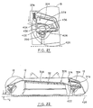
- Figures 13 to 20 show the lawn mower with the deck at a predetermined height H1 above the ground. (It can be appreciated that by controlling the height of the bottom of deck 12 with respect to the ground 426, the height of the lawn mower vegetation cutter or blade (not shown) relative to the ground will be necessarily adjusted.)
- the index pin 378 is shown in an index plate notch 406 corresponding to the highest elevation or height of the mower deck 12.
- the deck height is locked in the H1 position by virtue of the co-action of the counterbalance springs 396 and the index plate 402 to exert a clockwise and upwardly-directed force through index plate notch 406 upon index pin 378, which is resisted by the release handle biaser or spring 374.
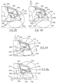
- the operator reaches into the release handle access port 322 as shown in Figure 16 and as indicated by arrow 434 in Figure 18. The operator then raises the release handle 324 which pivots the release handle clockwise about handle pivot 370, as shown in Figure 17.
- the axle has been rotated the entire angular distance spanned by the several teeth formed at the arcuate end the index plate 402.
- the index pin 378 is normally prevented from going past the terminal positions shown in Figure 19 and Figure 17 by the provision of enlarged teeth 436 upon both circumferential ends of the index plate 402.
- Figure 21 shows the position of the index pin 378 in locking engagement once again with the index plate 402 upon release by the operator of handle 324
- Figure 22 illustrates the position of the mower deck in the lowermost locked position.
- the index plate 402 is modified slightly to create a ramped notch surface 408, as seen in Figure 15A, and to add an arcuate land 438 between the last notch 406 and the rear-most enlarged index plate tooth 436.
- These modifications will enable the height-adjust systems of the present invention to cope with abnormally high external loads being placed on the deck, such as those which are approximately one hundred pounds. This feature will allow the deck to descend until it contacts the ground thereby short-circuiting or bypassing the load so it will not damage the height-adjust mechanism.
- the height-adjust system of the present invention is user-friendly, in that an operator can quickly and effortlessly change the height of the deck relative to all four wheels simultaneously.
- the sequence of operation has been described as the deck moving from a raised to a lowered position, conversely the operator may easily raise the deck from a lowered position as well, using the assist provided by the counterbalance springs. All the operator need do is press the release handle upwardly and grasp the adjacent portion of the deck in the same movement, and then simply apply upward force until the desired height is attained.
Landscapes
- Life Sciences & Earth Sciences (AREA)
- Environmental Sciences (AREA)
- Harvester Elements (AREA)
Applications Claiming Priority (3)
| Application Number | Priority Date | Filing Date | Title |
|---|---|---|---|
| US53199190A | 1990-06-01 | 1990-06-01 | |
| US531991 | 1990-06-01 | ||
| EP19910304131 EP0459638B1 (fr) | 1990-06-01 | 1991-05-08 | Tondeuse à gazon |
Related Parent Applications (1)
| Application Number | Title | Priority Date | Filing Date |
|---|---|---|---|
| EP91304131.5 Division | 1991-05-08 |
Publications (2)
| Publication Number | Publication Date |
|---|---|
| EP0670105A2 true EP0670105A2 (fr) | 1995-09-06 |
| EP0670105A3 EP0670105A3 (fr) | 1995-11-02 |
Family
ID=24119953
Family Applications (2)
| Application Number | Title | Priority Date | Filing Date |
|---|---|---|---|
| EP19910304131 Expired - Lifetime EP0459638B1 (fr) | 1990-06-01 | 1991-05-08 | Tondeuse à gazon |
| EP95201118A Withdrawn EP0670105A3 (fr) | 1990-06-01 | 1991-05-08 | Tondeuse à gazon. |
Family Applications Before (1)
| Application Number | Title | Priority Date | Filing Date |
|---|---|---|---|
| EP19910304131 Expired - Lifetime EP0459638B1 (fr) | 1990-06-01 | 1991-05-08 | Tondeuse à gazon |
Country Status (4)
| Country | Link |
|---|---|
| EP (2) | EP0459638B1 (fr) |
| AU (2) | AU7805691A (fr) |
| CA (3) | CA2090044A1 (fr) |
| DE (1) | DE69118245D1 (fr) |
Cited By (3)
| Publication number | Priority date | Publication date | Assignee | Title |
|---|---|---|---|---|
| GB2367475A (en) * | 2000-08-31 | 2002-04-10 | Bosch Gmbh Robert | Lawnmower height adjustment |
| US20140083072A1 (en) * | 2011-05-31 | 2014-03-27 | Husqvarna Ab | Height adjustment arrangement for a lawn mower |
| CN108650972A (zh) * | 2018-07-13 | 2018-10-16 | 安徽工程大学 | 一种石油勘探前处理用地面除草设备 |
Families Citing this family (6)
| Publication number | Priority date | Publication date | Assignee | Title |
|---|---|---|---|---|
| JP2599658B2 (ja) * | 1991-12-17 | 1997-04-09 | 本田技研工業株式会社 | 歩行式芝刈機 |
| US5526633A (en) * | 1994-08-12 | 1996-06-18 | Black & Decker Inc. | Lawn mower having improved deck height adjustment mechanism |
| US5749209A (en) * | 1996-09-05 | 1998-05-12 | Mtd Products Inc | Single lever height adjustment mechanism and method for a lawn mower |
| EP2724603B1 (fr) * | 2012-10-25 | 2016-05-25 | Robert Bosch Gmbh | Améliorations de/ou associées à un appareil d'entretien de jardin |
| CN113519276B (zh) * | 2020-04-16 | 2025-02-18 | 苏州宝时得电动工具有限公司 | 割草机的切割高度调节机构 |
| CN114430987B (zh) * | 2020-11-04 | 2025-09-19 | 苏州宝时得电动工具有限公司 | 割草机 |
Family Cites Families (6)
| Publication number | Priority date | Publication date | Assignee | Title |
|---|---|---|---|---|
| CH328972A (de) * | 1955-04-22 | 1958-04-15 | Risch Werner | Verstelleinrichtung an Rasenmähern |
| US3161006A (en) * | 1962-08-31 | 1964-12-15 | Hahn Inc | Adjustable rotary mower |
| US3269100A (en) * | 1964-07-15 | 1966-08-30 | Mcdonough Power Equipment Inc | Height adjustment mechanism for lawn mowers |
| US4321785A (en) * | 1980-12-08 | 1982-03-30 | Ataco Steel Products Co. | Wheel height adjuster |
| US4905463A (en) * | 1988-12-02 | 1990-03-06 | Canadiana Outdoor Products Inc. | Single action wheel height adjuster |
| US4899524A (en) * | 1988-12-02 | 1990-02-13 | Eilles Frank A | Height adjuster for lawn mowers |
-
1991
- 1991-04-24 CA CA 2090044 patent/CA2090044A1/fr not_active Abandoned
- 1991-04-24 CA CA 2041099 patent/CA2041099C/fr not_active Expired - Fee Related
- 1991-04-24 CA CA 2090045 patent/CA2090045A1/fr not_active Abandoned
- 1991-05-08 EP EP19910304131 patent/EP0459638B1/fr not_active Expired - Lifetime
- 1991-05-08 DE DE69118245T patent/DE69118245D1/de not_active Expired - Lifetime
- 1991-05-08 EP EP95201118A patent/EP0670105A3/fr not_active Withdrawn
- 1991-05-31 AU AU78056/91A patent/AU7805691A/en not_active Abandoned
-
1994
- 1994-12-08 AU AU80331/94A patent/AU8033194A/en not_active Abandoned
Cited By (5)
| Publication number | Priority date | Publication date | Assignee | Title |
|---|---|---|---|---|
| GB2367475A (en) * | 2000-08-31 | 2002-04-10 | Bosch Gmbh Robert | Lawnmower height adjustment |
| GB2367475B (en) * | 2000-08-31 | 2004-04-14 | Bosch Gmbh Robert | Lawncare machines |
| US20140083072A1 (en) * | 2011-05-31 | 2014-03-27 | Husqvarna Ab | Height adjustment arrangement for a lawn mower |
| US10470363B2 (en) * | 2011-05-31 | 2019-11-12 | Husqvarna Ab | Height adjustment arrangement for a lawn mower |
| CN108650972A (zh) * | 2018-07-13 | 2018-10-16 | 安徽工程大学 | 一种石油勘探前处理用地面除草设备 |
Also Published As
| Publication number | Publication date |
|---|---|
| CA2041099A1 (fr) | 1991-12-02 |
| DE69118245D1 (de) | 1996-05-02 |
| AU7805691A (en) | 1991-12-05 |
| CA2090044A1 (fr) | 1991-12-02 |
| CA2041099C (fr) | 1996-01-30 |
| AU8033194A (en) | 1995-02-16 |
| CA2090045A1 (fr) | 1991-12-02 |
| EP0670105A3 (fr) | 1995-11-02 |
| EP0459638B1 (fr) | 1996-03-27 |
| EP0459638A1 (fr) | 1991-12-04 |
Similar Documents
| Publication | Publication Date | Title |
|---|---|---|
| US5230208A (en) | Lawn mower height-adjust systems | |
| EP0670105A2 (fr) | Tondeuse à gazon | |
| CA1284275C (fr) | Dispositif regulateur de la garde au sol d'une tondeuse | |
| US12311818B2 (en) | Grounds maintenance vehicle with adjustable suspension system | |
| US9021776B2 (en) | Height of cut system for lawn mower | |
| EP2875710B1 (fr) | Système de réglage de hauteur de coupe de tondeuse à gazon | |
| US9370139B2 (en) | Reel mower with pivotal footrest providing access to center rear cutting unit | |
| US20150075882A1 (en) | Wheelchair | |
| CA2042776A1 (fr) | Dispositif de fixation de guidon pivotant de tondeuse | |
| EP3445155B1 (fr) | Tondeuse agraire à frein de stationnement | |
| US7540134B1 (en) | Riding mower with deck height adjustment | |
| EP1759569A1 (fr) | Tondeuse à gazon | |
| US20130270031A1 (en) | Suspension configuration for a seat | |
| GB2328359A (en) | Lawnmower. | |
| AU2018288056B2 (en) | Deck lift assembly for a riding lawn care vehicle | |
| EP0231642A2 (fr) | Chariot élévateur et procédé pour sa fabrication | |
| US20210227745A1 (en) | Grounds maintenance vehicle with adjustable implement angle | |
| US5662345A (en) | Wheelchair wheel cambering apparatus | |
| US4785519A (en) | Strut spring compressor | |
| WO1998002029A1 (fr) | Dispositif de commande de levee a mouvement perdu pour un chassis de tondeuse | |
| US2624168A (en) | Lawn mower construction | |
| US20220201933A1 (en) | Grounds maintenance vehicle | |
| US20070018369A1 (en) | Damping arrangement for lawn and garden care implement | |
| US20090309327A1 (en) | Wheelchair | |
| CN107912149B (zh) | 割草机的挡板安装结构及其安装方法 |
Legal Events
| Date | Code | Title | Description |
|---|---|---|---|
| PUAI | Public reference made under article 153(3) epc to a published international application that has entered the european phase |
Free format text: ORIGINAL CODE: 0009012 |
|
| AC | Divisional application: reference to earlier application |
Ref document number: 459638 Country of ref document: EP |
|
| AK | Designated contracting states |
Kind code of ref document: A2 Designated state(s): BE DE FR GB IT NL |
|
| PUAL | Search report despatched |
Free format text: ORIGINAL CODE: 0009013 |
|
| AK | Designated contracting states |
Kind code of ref document: A3 Designated state(s): BE DE FR GB IT NL |
|
| RIN1 | Information on inventor provided before grant (corrected) |
Inventor name: BOND, COURTNEY F. Inventor name: JACKSON, RONALD A. Inventor name: HARE, RONALD G. Inventor name: HESS, CHRISTOPHER A. |
|
| STAA | Information on the status of an ep patent application or granted ep patent |
Free format text: STATUS: THE APPLICATION IS DEEMED TO BE WITHDRAWN |
|
| 18D | Application deemed to be withdrawn |
Effective date: 19960503 |