EP0670129B1 - Vitrine avec un dispositif d'éclairage - Google Patents
Vitrine avec un dispositif d'éclairage Download PDFInfo
- Publication number
- EP0670129B1 EP0670129B1 EP94101696A EP94101696A EP0670129B1 EP 0670129 B1 EP0670129 B1 EP 0670129B1 EP 94101696 A EP94101696 A EP 94101696A EP 94101696 A EP94101696 A EP 94101696A EP 0670129 B1 EP0670129 B1 EP 0670129B1
- Authority
- EP
- European Patent Office
- Prior art keywords
- display case
- fibre
- bases
- cable
- optic cables
- Prior art date
- Legal status (The legal status is an assumption and is not a legal conclusion. Google has not performed a legal analysis and makes no representation as to the accuracy of the status listed.)
- Expired - Lifetime
Links
- 239000012780 transparent material Substances 0.000 claims description 2
- NJPPVKZQTLUDBO-UHFFFAOYSA-N novaluron Chemical compound C1=C(Cl)C(OC(F)(F)C(OC(F)(F)F)F)=CC=C1NC(=O)NC(=O)C1=C(F)C=CC=C1F NJPPVKZQTLUDBO-UHFFFAOYSA-N 0.000 claims 1
- 230000003287 optical effect Effects 0.000 abstract description 4
- 239000008259 solid foam Substances 0.000 abstract 1
- 238000005286 illumination Methods 0.000 description 10
- 230000005855 radiation Effects 0.000 description 5
- 239000011521 glass Substances 0.000 description 3
- 239000003990 capacitor Substances 0.000 description 2
- 239000000463 material Substances 0.000 description 2
- 238000001816 cooling Methods 0.000 description 1
- 230000001419 dependent effect Effects 0.000 description 1
- 238000011161 development Methods 0.000 description 1
- 230000018109 developmental process Effects 0.000 description 1
- 238000001914 filtration Methods 0.000 description 1
- 239000006260 foam Substances 0.000 description 1
- 238000010438 heat treatment Methods 0.000 description 1
- 238000003780 insertion Methods 0.000 description 1
- 230000037431 insertion Effects 0.000 description 1
- 238000009434 installation Methods 0.000 description 1
- 238000009413 insulation Methods 0.000 description 1
- 239000000203 mixture Substances 0.000 description 1
- 239000013307 optical fiber Substances 0.000 description 1
Images




Classifications
-
- A—HUMAN NECESSITIES
- A47—FURNITURE; DOMESTIC ARTICLES OR APPLIANCES; COFFEE MILLS; SPICE MILLS; SUCTION CLEANERS IN GENERAL
- A47F—SPECIAL FURNITURE, FITTINGS, OR ACCESSORIES FOR SHOPS, STOREHOUSES, BARS, RESTAURANTS OR THE LIKE; PAYING COUNTERS
- A47F3/00—Show cases or show cabinets
- A47F3/001—Devices for lighting, humidifying, heating, ventilation
-
- G—PHYSICS
- G02—OPTICS
- G02B—OPTICAL ELEMENTS, SYSTEMS OR APPARATUS
- G02B6/00—Light guides; Structural details of arrangements comprising light guides and other optical elements, e.g. couplings
- G02B6/0001—Light guides; Structural details of arrangements comprising light guides and other optical elements, e.g. couplings specially adapted for lighting devices or systems
- G02B6/0005—Light guides; Structural details of arrangements comprising light guides and other optical elements, e.g. couplings specially adapted for lighting devices or systems the light guides being of the fibre type
- G02B6/0008—Light guides; Structural details of arrangements comprising light guides and other optical elements, e.g. couplings specially adapted for lighting devices or systems the light guides being of the fibre type the light being emitted at the end of the fibre
-
- F—MECHANICAL ENGINEERING; LIGHTING; HEATING; WEAPONS; BLASTING
- F21—LIGHTING
- F21W—INDEXING SCHEME ASSOCIATED WITH SUBCLASSES F21K, F21L, F21S and F21V, RELATING TO USES OR APPLICATIONS OF LIGHTING DEVICES OR SYSTEMS
- F21W2131/00—Use or application of lighting devices or systems not provided for in codes F21W2102/00-F21W2121/00
- F21W2131/40—Lighting for industrial, commercial, recreational or military use
- F21W2131/405—Lighting for industrial, commercial, recreational or military use for shop-windows or displays
Definitions
- the invention relates to a display case for displaying objects with a lighting device and with a plurality of side surfaces consisting of transparent material, a lower part formed as a base and an upper part forming the upper side, in which the lighting device is located.
- Such a display case is already known.
- the lighting device in the upper part of the display case, the side surfaces of which are made of glass, is designed in the form of light emitters by means of which the objects located in the display case are illuminated.
- a disadvantage is the heat generated during the generation of light, which can heat up the interior of the showcase, especially when strong and uniform lighting is desired.
- a large number of light emitters in the form of incandescent lamps or fluorescent lamps are generally necessary for this.
- the object of the invention is to provide a display case of the type mentioned, in which the heating of the interior of the display case is avoided with strong and uniform lighting.
- the upper part contains a lighting source with a plurality of light guide cables connected to it, the end pieces of which protrude through the underside of the upper part, that one or more intermediate floors are attached between the upper part and the lower part, that further light guide cables from the upper part to the each intermediate floor are guided and end there with their end pieces in the underside, that the underside of the upper part and the underside of the intermediate floors each consist of a plate in which the end pieces of the light guide cables are held, that a vertical cable duct between the inside of a side surface the upper part and the lower part for receiving the light guide cable leading to the intermediate floor or floors is attached such that each intermediate floor has a cavity for receiving the light guide cable, which is accessible from the outside through an opening in the area of the cable duct, that the or the height of the intermediate shelves is or are adjustable and that the cable duct has a vertical slot directed towards the interior of the display case.
- the light guide can the infrared portion of the light radiation can also be additionally reduced.
- GB-A-2 206 786 describes a lighting device for objects placed on the shelf, in which light guide cables guided in the rear wall of the shelf end in the floors and are directed upwards or downwards, so that the lighting on the Floor lying objects from below and also from above is possible.
- the light guide cables are connected to a common light source, the cited document leaving open where this light source is attached.
- EP-A-0 388 128 describes a lighting device for a refrigerated display case, in which the light source is attached to the top of the refrigerated display case and to which a plurality of light-conducting cables are connected, which either end below the top surface or are guided through the door frame end in the interior of the refrigerated display case, so that the objects located in the interior of the refrigerated display case can be illuminated from above and from the front, without causing an increase in temperature in the interior of the refrigerated display case.
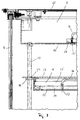
- the showcase 1 consists of four glass side surfaces 2, 3, 4 and 5, which are attached between the lower part 6, which is designed as a base, and the upper part 7, which forms the upper side.
- One or more side surfaces can be designed as a pivotable or slidable door 2, which can be closed by locks 8.
- the display case 1 has a square cross section.
- the invention is also applicable to showcases with a pentagonal and polygonal layout.
- a lighting source 19 is accommodated, the heat of which is dissipated to the outside by convection cooling or a fan, not shown, through the correspondingly designed cover 23 of the upper part 7.
- the upper part 7 can also be additionally shielded in the area of the illumination source 19 by suitable thermal insulation against the interior of the display case 1.
- suitable filters 20 for filtering the radiation harmful to the objects located in the display case 1 (for example infrared radiation, UV radiation, etc.), a variety of optical cables 16 connected.
- a lens system for example an optical capacitor, can be used between the illumination source 19 and the light guide cables 16, for example an optical capacitor for more uniform light distribution in the case of particularly strong light guide cable bundles.
- Each light guide cable 16 ends in an end piece 17, at which the light radiation generated by the illumination source 19 exits. If necessary, the end pieces 17 can also each have a lens for light distribution or also for light concentration.
- the end pieces 17 are each held in a common plate 24, for example made of rigid foam, which is provided with corresponding bores for receiving the end pieces 17.
- the size of the holes is also dependent on the material and should be chosen so that the end pieces 17 can be pressed into them, but are then held securely and permanently in the hole.
- the plate 24 is either attached only to the underside 14 of the upper part 7 or also to the underside 15 of intermediate floors 9.
- the plate 24 is inserted from above after removing the cover 23, while the plate 24 can be inserted into the intermediate floor 9 after removing the support plate 28.
- the plates 24 are held in the upper part 6 and in the intermediate floors 9 in the area of their outer edges.
- the plates 24 are provided with regularly distributed bores for receiving the end pieces 17 of the light guide cables, the arrangement and frequency distribution depending on the type of lighting desired.
- the plate 24 can also be exchangeable by Depending on the desired brightness or light distribution, corresponding plates 24 are kept ready, into which only the end pieces 17 with their light guide cable 16 are to be plugged before insertion. This can also be done later at the installation site respectively.
- the light guide cables 16 which may not be required for the current application need not be pulled out of the intermediate floor 9 and through the cable duct 11 into the upper part 7 but can remain in the cavity 25 of the relevant intermediate floor 9.
- the display case 1 can also have one or more intermediate shelves 9 which are held by vertical rods 13 fastened to the upper part 6 and the lower part 7.
- the rods 13 are each installed in the corner of two abutting side surfaces in the interior of the display case.
- the intermediate floors 9 are provided with corresponding bores 29 for receiving the rods 13 and are firmly connected to them or can also be moved vertically up and down on the rods 13, whereby they can be fastened to the rod 13 in the desired position by one each Locking ring 18 are held. This allows a fixed and detachable connection to the rod 13, for example, by means of attached adjusting screws.
- the locking rings 18 can sit concealed between the support plate 28 and the underside 15 of an intermediate floor 9 and can only be accessed after removal of a side cover (not shown) of the intermediate floor 9.
- a vertical, closed cable duct 11 is provided in the area of the rear side surface 5, which serves to guide the light guide cables 16 from the illumination source 19 located in the upper part 6 to the intermediate floors 9.
- the light guide cables 16 for an intermediate floor 9 emerge from the cable duct 11 at the same height and pass through an opening 26 into the cavity 25 of the intermediate floor 9 formed by the support plate 28 and the plate 24.
- the cable duct 11 is only to be provided with a corresponding outlet opening (not shown) in the region of the opening 26 of the intermediate floor 9, which is covered by the intermediate floor 9.
- the cable duct 11 is vertical and to provide a centrally running slot 12 for the exit of the light guide cables 16 therefrom.
- the width of the slot 12 depends on the width of the optical fiber bundle of an intermediate floor 9.
- the light guide cable bundle for one intermediate floor 9 on one side of the cable duct 11 and the light guide cable bundle for the other intermediate floor 9 on the other side of the cable duct 11 can be guided in each case in a space 27 within the cable duct 11 , which is formed in each case by webs 21 outside the slot 12.
- the webs 21 are designed as narrow projections at regular intervals, the distance between two webs having to correspond to at least the thickness of a light guide cable bundle so that it can be led out of the cable duct 11. If the power supply for the illumination source 19 takes place from the floor 22, the power cable (not shown) can also be led from the lower part 6 through the cable duct 11 to the illumination source 19 in the upper part 7.
Landscapes
- Physics & Mathematics (AREA)
- General Physics & Mathematics (AREA)
- Optics & Photonics (AREA)
- Freezers Or Refrigerated Showcases (AREA)
- Devices That Are Associated With Refrigeration Equipment (AREA)
- Non-Portable Lighting Devices Or Systems Thereof (AREA)
Claims (7)
- Vitrine pour exposer des objets avec un dispositif d'éclairage et avec plusieurs flancs (2, 3, 4, 5)en matière transparente, une partie (6) inférieure formée comme un socle et une partie (7) supérieure formant le dessus, dans laquelle se trouve le dispositif d'éclairage, caractérisée en ce que la partie (7) supérieure comprend une source (19) d'éclairage avec une multiplicité de câbles (16) fibres optiques qui y sont connectés et dont les extrémités (17) font saillie de la face (14) inférieure de la partie (7) supérieure, par le fait qu'une ou plusieurs planches (9 intermédiaires sont placées entre la partie (7) supérieure et la partie (6) inférieure, par le fait que d'autres câbles (16) fibres optiques vont de la partie (7) supérieure aux planches (9) intermédiaires respectives et se terminent là avec leurs extrémités (17) dans la face (15) inférieure, par le fait que la face (14) inférieure de la partie (7) supérieure et la face inférieure (15) des planches (9) intermédiaires sont respectivement constituées d'une plaque (24) dans laquelle les extrémités (17) des câbles (16) fibres optiques sont maintenus, par le fait que dans la région de la face intérieure d'un flanc (3, 4, 5) une gaine (11) verticale est placée entre la partie (7) supérieure et la partie (6) inférieure pour recevoir les câbles (16) fibres optiques allant jusqu'à la ou encore les planches (9) intermédiaires, par le fait que chaque planche (9) intermédiaire présente un vide (25) pour recevoir les câbles (16) fibres optiques, qui est accessible de l'extérieur par une ouverture (26) dans la région de la gaine (11), par le fait que la ou encore les planches (9) intermédiaires peut ou encore peuvent être réglées en hauteur et par le fait que la gaine (11) présente une fente (12) verticale orientée vers l'intérieur de la vitrine.
- Vitrine selon la revendication 1, caractérisée en ce que la fente (12) de la gaine (11) s'étend en son centre et en ce que la gaine présente en dehors des régions des planches (9) intermédiaires à chaque fois des deux côtés de la fente (12) un espace (27) pour recevoir les câbles (16) fibres optiques, qui est limité par une traverse (21) placée dans la région de la fente (12).
- Vitrine selon une des revendications 1 ou 2, caractérisée en ce que la plaque (24) peut être remplacée
- Vitrine selon une des revendications 1 à 3, caractérisée en ce que différentes plaques sont pourvues de dispositions différentes des orifices pour recevoir à chaque fois une extrémité (17) d'un câble (16) fibre optique.
- Vitrine selon une des revendications 1 à 4, caractérisée en ce que chaque fois dans la région où deux flancs (2, 3, 4, 5) se touchent par leurs bords verticaux, une barre (13) verticale, sur laquelle la ou encore les planches (9) intermédiaires sont fixées par des moyens (18) appropriés, est placée entre la partie (7) supérieure et la partie (6) inférieure.
- Vitrine selon une des revendications 1 à 5, caractérisée en ce qu'un câble de distribution pour le dispositif (19, 20) d'éclairage pénètre dans la partie inférieure (6) de la vitrine (1) et est amené par la gaine (11) dans la partie supérieure (7).
- Vitrine selon une des revendications 1 à 6, caractérisée en ce qu'entre la source (19) d'éclairage et les câbles (16) fibres optiques, il est prévu un filtre (20) par lequel est retenue une fraction du rayonnement provenant de la source lumineuse (19), nuisible pour les objets exposés dans la vitrine (1).
Priority Applications (3)
| Application Number | Priority Date | Filing Date | Title |
|---|---|---|---|
| DE59402753T DE59402753D1 (de) | 1994-02-04 | 1994-02-04 | Vitrine mit einer Beleuchtungseinrichtung |
| EP94101696A EP0670129B1 (fr) | 1994-02-04 | 1994-02-04 | Vitrine avec un dispositif d'éclairage |
| AT94101696T ATE152892T1 (de) | 1994-02-04 | 1994-02-04 | Vitrine mit einer beleuchtungseinrichtung |
Applications Claiming Priority (1)
| Application Number | Priority Date | Filing Date | Title |
|---|---|---|---|
| EP94101696A EP0670129B1 (fr) | 1994-02-04 | 1994-02-04 | Vitrine avec un dispositif d'éclairage |
Publications (2)
| Publication Number | Publication Date |
|---|---|
| EP0670129A1 EP0670129A1 (fr) | 1995-09-06 |
| EP0670129B1 true EP0670129B1 (fr) | 1997-05-14 |
Family
ID=8215654
Family Applications (1)
| Application Number | Title | Priority Date | Filing Date |
|---|---|---|---|
| EP94101696A Expired - Lifetime EP0670129B1 (fr) | 1994-02-04 | 1994-02-04 | Vitrine avec un dispositif d'éclairage |
Country Status (3)
| Country | Link |
|---|---|
| EP (1) | EP0670129B1 (fr) |
| AT (1) | ATE152892T1 (fr) |
| DE (1) | DE59402753D1 (fr) |
Cited By (1)
| Publication number | Priority date | Publication date | Assignee | Title |
|---|---|---|---|---|
| EP2051004A1 (fr) | 2007-10-19 | 2009-04-22 | Elmar Schrutek | Eclairage, notamment pour des vitrines ou des vitrines d'exposition |
Families Citing this family (6)
| Publication number | Priority date | Publication date | Assignee | Title |
|---|---|---|---|---|
| DE20008446U1 (de) | 2000-05-11 | 2000-08-17 | Glasbau Hahn GmbH + Co. KG, 60314 Frankfurt | Beleuchtungseinrichtung für eine Vitrine |
| ES2246463T3 (es) * | 2003-02-03 | 2006-02-16 | Bocchini S.P.A. | Mostrador refrigerado equipado con un sistema de iluminacion por fibra optica. |
| EP1858375A1 (fr) * | 2005-02-15 | 2007-11-28 | Carrier Corporation | Presentoir eclaire |
| EP1767850A1 (fr) * | 2005-09-23 | 2007-03-28 | Goppion S.p.A. | Dispositif d'éclairage amélioré pour vitrine, et vitrine comprenant un tel dispositif |
| CN108969780A (zh) * | 2018-08-21 | 2018-12-11 | 四川健尔莱医疗器械科技有限公司 | 一种不会二次污染的紫外线消毒装置 |
| JP7421583B2 (ja) * | 2022-03-10 | 2024-01-24 | ソマール株式会社 | 物品の鑑賞等用什器 |
Family Cites Families (3)
| Publication number | Priority date | Publication date | Assignee | Title |
|---|---|---|---|---|
| GB8712791D0 (en) * | 1987-06-01 | 1987-07-08 | Neave A J | Display cabinet |
| GB8905684D0 (en) * | 1989-03-13 | 1989-04-26 | Less Lighting Ltd | Apparatus for illuminating an environment which operates below normal ambient temperature |
| DE4006004A1 (de) * | 1990-02-26 | 1991-08-29 | Friedhelm Buers | Dekorationsgegenstand mit beleuchteten profilschienen |
-
1994
- 1994-02-04 DE DE59402753T patent/DE59402753D1/de not_active Expired - Fee Related
- 1994-02-04 EP EP94101696A patent/EP0670129B1/fr not_active Expired - Lifetime
- 1994-02-04 AT AT94101696T patent/ATE152892T1/de active
Cited By (1)
| Publication number | Priority date | Publication date | Assignee | Title |
|---|---|---|---|---|
| EP2051004A1 (fr) | 2007-10-19 | 2009-04-22 | Elmar Schrutek | Eclairage, notamment pour des vitrines ou des vitrines d'exposition |
Also Published As
| Publication number | Publication date |
|---|---|
| DE59402753D1 (de) | 1997-06-19 |
| EP0670129A1 (fr) | 1995-09-06 |
| ATE152892T1 (de) | 1997-05-15 |
Similar Documents
| Publication | Publication Date | Title |
|---|---|---|
| DE4006004C2 (fr) | ||
| EP0901332B1 (fr) | Systeme modulaire d'amenagement interieur | |
| DE4028000C2 (fr) | ||
| DE3343066A1 (de) | Moebel mit hoehen- und/oder neigungsverstellbarer tischplatte | |
| DE19804902A1 (de) | Schaltschrank | |
| DE20005154U1 (de) | Dunstabzugshaube | |
| DE102011057097A1 (de) | Decken-Beleuchtungsanordnung | |
| EP0670129A1 (fr) | Vitrine avec un dispositif d'ecclairage | |
| EP2542829B1 (fr) | Dispositif pour éclairer des pièces | |
| EP0706771B1 (fr) | Système modulaire de meubles | |
| EP0469179B1 (fr) | Système d'éclairage modulaire | |
| DE2130511C3 (de) | Regalmöbel mit an Ständern angebrachten Fächern | |
| EP0518261A1 (fr) | Table de travail avec appareils électriques incorporés | |
| DE60301049T2 (de) | Kühltheke mit optischem Faserbeleuchtungssystem | |
| DE4440978C2 (de) | Vitrine | |
| DE2130512A1 (de) | Regalmoebel | |
| DE4446435A1 (de) | Vitrine mit einer Beleuchtungseinrichtung | |
| DE202004007633U1 (de) | Pflanzenzuchtvorrichtung | |
| DE3224709C2 (de) | Regal | |
| DE29704305U1 (de) | Geräteschrank | |
| DE19653341A1 (de) | Beleuchtungsvorrichtung | |
| DE19811759C1 (de) | Schaltschrank oder Schaltgestell | |
| DE4316996C2 (de) | Vorrichtung zur Präsentation von flächenhaften Objekten | |
| DE19811745C1 (de) | Schaltschrank- oder Schaltgestell-Reihe | |
| DE9407032U1 (de) | Regal |
Legal Events
| Date | Code | Title | Description |
|---|---|---|---|
| PUAI | Public reference made under article 153(3) epc to a published international application that has entered the european phase |
Free format text: ORIGINAL CODE: 0009012 |
|
| 17P | Request for examination filed |
Effective date: 19941228 |
|
| AK | Designated contracting states |
Kind code of ref document: A1 Designated state(s): AT BE CH DE DK ES FR GB LI LU NL |
|
| RBV | Designated contracting states (corrected) |
Designated state(s): AT BE CH DE DK ES FR GB LI LU NL |
|
| GRAG | Despatch of communication of intention to grant |
Free format text: ORIGINAL CODE: EPIDOS AGRA |
|
| 17Q | First examination report despatched |
Effective date: 19960318 |
|
| GRAH | Despatch of communication of intention to grant a patent |
Free format text: ORIGINAL CODE: EPIDOS IGRA |
|
| GRAH | Despatch of communication of intention to grant a patent |
Free format text: ORIGINAL CODE: EPIDOS IGRA |
|
| GRAA | (expected) grant |
Free format text: ORIGINAL CODE: 0009210 |
|
| AK | Designated contracting states |
Kind code of ref document: B1 Designated state(s): AT BE CH DE DK ES FR GB LI LU NL |
|
| PG25 | Lapsed in a contracting state [announced via postgrant information from national office to epo] |
Ref country code: NL Free format text: LAPSE BECAUSE OF FAILURE TO SUBMIT A TRANSLATION OF THE DESCRIPTION OR TO PAY THE FEE WITHIN THE PRESCRIBED TIME-LIMIT Effective date: 19970514 Ref country code: ES Free format text: THE PATENT HAS BEEN ANNULLED BY A DECISION OF A NATIONAL AUTHORITY Effective date: 19970514 Ref country code: DK Effective date: 19970514 |
|
| REF | Corresponds to: |
Ref document number: 152892 Country of ref document: AT Date of ref document: 19970515 Kind code of ref document: T |
|
| REG | Reference to a national code |
Ref country code: CH Ref legal event code: NV Representative=s name: E. BLUM & CO. PATENTANWAELTE Ref country code: CH Ref legal event code: EP |
|
| GBT | Gb: translation of ep patent filed (gb section 77(6)(a)/1977) |
Effective date: 19970515 |
|
| REF | Corresponds to: |
Ref document number: 59402753 Country of ref document: DE Date of ref document: 19970619 |
|
| ET | Fr: translation filed | ||
| NLV1 | Nl: lapsed or annulled due to failure to fulfill the requirements of art. 29p and 29m of the patents act | ||
| PLBE | No opposition filed within time limit |
Free format text: ORIGINAL CODE: 0009261 |
|
| STAA | Information on the status of an ep patent application or granted ep patent |
Free format text: STATUS: NO OPPOSITION FILED WITHIN TIME LIMIT |
|
| 26N | No opposition filed | ||
| PGFP | Annual fee paid to national office [announced via postgrant information from national office to epo] |
Ref country code: FR Payment date: 20010215 Year of fee payment: 8 |
|
| PGFP | Annual fee paid to national office [announced via postgrant information from national office to epo] |
Ref country code: GB Payment date: 20010220 Year of fee payment: 8 |
|
| PGFP | Annual fee paid to national office [announced via postgrant information from national office to epo] |
Ref country code: AT Payment date: 20010221 Year of fee payment: 8 Ref country code: CH Payment date: 20010221 Year of fee payment: 8 Ref country code: BE Payment date: 20010221 Year of fee payment: 8 |
|
| PGFP | Annual fee paid to national office [announced via postgrant information from national office to epo] |
Ref country code: LU Payment date: 20010223 Year of fee payment: 8 Ref country code: DE Payment date: 20010223 Year of fee payment: 8 |
|
| REG | Reference to a national code |
Ref country code: GB Ref legal event code: IF02 |
|
| PG25 | Lapsed in a contracting state [announced via postgrant information from national office to epo] |
Ref country code: LU Free format text: LAPSE BECAUSE OF NON-PAYMENT OF DUE FEES Effective date: 20020204 Ref country code: GB Free format text: LAPSE BECAUSE OF NON-PAYMENT OF DUE FEES Effective date: 20020204 Ref country code: AT Free format text: LAPSE BECAUSE OF NON-PAYMENT OF DUE FEES Effective date: 20020204 |
|
| PG25 | Lapsed in a contracting state [announced via postgrant information from national office to epo] |
Ref country code: LI Free format text: LAPSE BECAUSE OF NON-PAYMENT OF DUE FEES Effective date: 20020228 Ref country code: CH Free format text: LAPSE BECAUSE OF NON-PAYMENT OF DUE FEES Effective date: 20020228 Ref country code: BE Free format text: LAPSE BECAUSE OF NON-PAYMENT OF DUE FEES Effective date: 20020228 |
|
| BERE | Be: lapsed |
Owner name: GLASBAU HAHN G.M.B.H. & CO. K.G. Effective date: 20020228 |
|
| PG25 | Lapsed in a contracting state [announced via postgrant information from national office to epo] |
Ref country code: DE Free format text: LAPSE BECAUSE OF NON-PAYMENT OF DUE FEES Effective date: 20020903 |
|
| GBPC | Gb: european patent ceased through non-payment of renewal fee |
Effective date: 20020204 |
|
| REG | Reference to a national code |
Ref country code: CH Ref legal event code: PL |
|
| PG25 | Lapsed in a contracting state [announced via postgrant information from national office to epo] |
Ref country code: FR Free format text: LAPSE BECAUSE OF NON-PAYMENT OF DUE FEES Effective date: 20021031 |
|
| REG | Reference to a national code |
Ref country code: FR Ref legal event code: ST |