EP0670432A2 - Montage de palier pour un arbre - Google Patents
Montage de palier pour un arbre Download PDFInfo
- Publication number
- EP0670432A2 EP0670432A2 EP95102306A EP95102306A EP0670432A2 EP 0670432 A2 EP0670432 A2 EP 0670432A2 EP 95102306 A EP95102306 A EP 95102306A EP 95102306 A EP95102306 A EP 95102306A EP 0670432 A2 EP0670432 A2 EP 0670432A2
- Authority
- EP
- European Patent Office
- Prior art keywords
- bearing
- recess
- housing
- arrangement according
- shaft
- Prior art date
- Legal status (The legal status is an assumption and is not a legal conclusion. Google has not performed a legal analysis and makes no representation as to the accuracy of the status listed.)
- Withdrawn
Links
- 238000005096 rolling process Methods 0.000 claims abstract description 30
- 238000009826 distribution Methods 0.000 claims abstract description 12
- 238000004519 manufacturing process Methods 0.000 claims description 5
- 230000005540 biological transmission Effects 0.000 description 10
- 230000015572 biosynthetic process Effects 0.000 description 3
- 238000013461 design Methods 0.000 description 3
- 238000011161 development Methods 0.000 description 3
- 230000018109 developmental process Effects 0.000 description 3
- 238000012360 testing method Methods 0.000 description 3
- 230000002411 adverse Effects 0.000 description 2
- 229910052782 aluminium Inorganic materials 0.000 description 2
- XAGFODPZIPBFFR-UHFFFAOYSA-N aluminium Chemical compound [Al] XAGFODPZIPBFFR-UHFFFAOYSA-N 0.000 description 2
- 238000004364 calculation method Methods 0.000 description 2
- 238000004590 computer program Methods 0.000 description 2
- 238000010276 construction Methods 0.000 description 2
- 238000006073 displacement reaction Methods 0.000 description 2
- 238000003860 storage Methods 0.000 description 2
- 230000007423 decrease Effects 0.000 description 1
- 230000003247 decreasing effect Effects 0.000 description 1
- 230000000694 effects Effects 0.000 description 1
- 238000009434 installation Methods 0.000 description 1
- 229910052751 metal Inorganic materials 0.000 description 1
- 239000002184 metal Substances 0.000 description 1
- 238000000034 method Methods 0.000 description 1
- 238000012986 modification Methods 0.000 description 1
- 230000004048 modification Effects 0.000 description 1
- 230000002093 peripheral effect Effects 0.000 description 1
- 238000012546 transfer Methods 0.000 description 1
Images

Classifications
-
- F—MECHANICAL ENGINEERING; LIGHTING; HEATING; WEAPONS; BLASTING
- F16—ENGINEERING ELEMENTS AND UNITS; GENERAL MEASURES FOR PRODUCING AND MAINTAINING EFFECTIVE FUNCTIONING OF MACHINES OR INSTALLATIONS; THERMAL INSULATION IN GENERAL
- F16H—GEARING
- F16H57/00—General details of gearing
- F16H57/02—Gearboxes; Mounting gearing therein
- F16H57/021—Shaft support structures, e.g. partition walls, bearing eyes, casing walls or covers with bearings
-
- F—MECHANICAL ENGINEERING; LIGHTING; HEATING; WEAPONS; BLASTING
- F16—ENGINEERING ELEMENTS AND UNITS; GENERAL MEASURES FOR PRODUCING AND MAINTAINING EFFECTIVE FUNCTIONING OF MACHINES OR INSTALLATIONS; THERMAL INSULATION IN GENERAL
- F16C—SHAFTS; FLEXIBLE SHAFTS; ELEMENTS OR CRANKSHAFT MECHANISMS; ROTARY BODIES OTHER THAN GEARING ELEMENTS; BEARINGS
- F16C27/00—Elastic or yielding bearings or bearing supports, for exclusively rotary movement
- F16C27/04—Ball or roller bearings, e.g. with resilient rolling bodies
-
- F—MECHANICAL ENGINEERING; LIGHTING; HEATING; WEAPONS; BLASTING
- F16—ENGINEERING ELEMENTS AND UNITS; GENERAL MEASURES FOR PRODUCING AND MAINTAINING EFFECTIVE FUNCTIONING OF MACHINES OR INSTALLATIONS; THERMAL INSULATION IN GENERAL
- F16C—SHAFTS; FLEXIBLE SHAFTS; ELEMENTS OR CRANKSHAFT MECHANISMS; ROTARY BODIES OTHER THAN GEARING ELEMENTS; BEARINGS
- F16C35/00—Rigid support of bearing units; Housings, e.g. caps, covers
- F16C35/04—Rigid support of bearing units; Housings, e.g. caps, covers in the case of ball or roller bearings
- F16C35/042—Housings for rolling element bearings for rotary movement
- F16C35/047—Housings for rolling element bearings for rotary movement with a base plate substantially parallel to the axis of rotation, e.g. horizontally mounted pillow blocks
-
- F—MECHANICAL ENGINEERING; LIGHTING; HEATING; WEAPONS; BLASTING
- F16—ENGINEERING ELEMENTS AND UNITS; GENERAL MEASURES FOR PRODUCING AND MAINTAINING EFFECTIVE FUNCTIONING OF MACHINES OR INSTALLATIONS; THERMAL INSULATION IN GENERAL
- F16C—SHAFTS; FLEXIBLE SHAFTS; ELEMENTS OR CRANKSHAFT MECHANISMS; ROTARY BODIES OTHER THAN GEARING ELEMENTS; BEARINGS
- F16C2361/00—Apparatus or articles in engineering in general
- F16C2361/61—Toothed gear systems, e.g. support of pinion shafts
-
- F—MECHANICAL ENGINEERING; LIGHTING; HEATING; WEAPONS; BLASTING
- F16—ENGINEERING ELEMENTS AND UNITS; GENERAL MEASURES FOR PRODUCING AND MAINTAINING EFFECTIVE FUNCTIONING OF MACHINES OR INSTALLATIONS; THERMAL INSULATION IN GENERAL
- F16C—SHAFTS; FLEXIBLE SHAFTS; ELEMENTS OR CRANKSHAFT MECHANISMS; ROTARY BODIES OTHER THAN GEARING ELEMENTS; BEARINGS
- F16C35/00—Rigid support of bearing units; Housings, e.g. caps, covers
- F16C35/04—Rigid support of bearing units; Housings, e.g. caps, covers in the case of ball or roller bearings
- F16C35/06—Mounting or dismounting of ball or roller bearings; Fixing them onto shaft or in housing
- F16C35/067—Fixing them in a housing
-
- F—MECHANICAL ENGINEERING; LIGHTING; HEATING; WEAPONS; BLASTING
- F16—ENGINEERING ELEMENTS AND UNITS; GENERAL MEASURES FOR PRODUCING AND MAINTAINING EFFECTIVE FUNCTIONING OF MACHINES OR INSTALLATIONS; THERMAL INSULATION IN GENERAL
- F16H—GEARING
- F16H57/00—General details of gearing
- F16H57/02—Gearboxes; Mounting gearing therein
- F16H2057/02039—Gearboxes for particular applications
- F16H2057/02043—Gearboxes for particular applications for vehicle transmissions
Definitions
- the invention relates to a bearing arrangement for supporting a shaft, which is particularly loaded by radial forces, with a roller bearing that supports the shaft and is received by a bearing recess in a bearing housing.
- Bearings loaded radially on one side are known in particular from the construction of gears.
- torques are transmitted between two or more shafts via toothings, as a result of which forces are formed between the shafts which essentially push the mutually interacting shafts away from one another.
- the force directions acting on the bearings can deviate from the plane spanned by the shaft axes involved.
- the shaft bearings absorb the forces and transfer them to the bearing housing.
- the load is generally not uniformly distributed over all rolling elements of the rolling bearing. Rather, there is a strong increase in the load on the rolling elements, which are each under load in the area of the direction of force.
- the maximum load in the bearing limits its area of application and service life.
- the bearing dimensioning is essentially determined by their load.
- the decisive factor here is the maximum forces that occur on the rolling elements of the bearing located in the direction of force.
- a bearing unit for mounting the output shaft of a tractor transmission which contains a radial bearing arrangement of the type mentioned at the outset for supporting radial forces, which has a in a recess of the gear housing has guided radial bearing.
- the bearing unit also contains an axial bearing unit with two axial cylindrical roller bearings, which are supported on the gear housing via a flange designated as a bearing housing.
- it is proposed to provide sections of different stiffness in the circumferential direction on the flange in its radial ring region between the contact of the axial bearing unit and the fastening region on the gear housing.
- the rigidity of the flange is reduced in those circumferential areas in which the main load occurring due to shaft deflection occurs. Measures for dimensioning the radial bearing arrangement are not specified. In particular, the problem is not dealt with, how an increase in the load in the radial direction of force on the rolling elements of the radial bearing enclosed between an inner and an outer bearing ring could be counteracted.
- DE-GM-84 24 844 relates to a flange bearing with a flat bearing bracket and a bearing bush attached to it with a running layer.
- the bearing bush should be coaxial with the shaft mounted in it.
- JP-A-4-25 621 suggests storage that is to remain dimensionally stable in the event of temperature changes.
- an aluminum spindle hub is supported by a ball bearing on a stationary shaft.
- a ring-shaped, The slot concentrically surrounding the ball bearing is embedded in the spindle hub in such a way that a thin cylindrical part which rests on the peripheral surface of the ball bearing is formed.
- the aluminum hub expands more than the ball bearing.
- the shrinkage should be compensated for by a deformation of the cylindrical part.
- the publication does not show how one-sided excessive forces acting on the bearing could be controlled.
- the object on which the invention is based is seen in specifying a bearing arrangement of the type mentioned at the outset by which excessive radial forces are mastered and the bearing life can be extended even when relatively small roller bearings are used.
- the essential teaching of the invention consists in broadening the load distribution on the rolling elements of the rolling bearing and thereby reducing the pressure on the most heavily loaded rolling elements. This is done by reducing the housing stiffness in the radial direction of force compared to the housing stiffness in other radial directions. This measure basically maintains the housing rigidity. By specifically increasing the resilience of the housing in the area of the direction of force acting on the bearing, the load distribution in the bearing can be broadened, so that more rolling elements are involved in carrying and the average load on the rolling element lying in the direction of force is reduced.
- the load is distributed approximately evenly over several rolling elements.
- the average load on the central rolling element lying in the direction of the force can be reduced, for example, by 20%. This leads to a considerable increase in the life of the bearing, so that smaller, cheaper bearings can be used compared to conventional designs.
- the bearing arrangement according to the invention is used in a particularly advantageous manner where high loads on the bearing which are to be avoided are found in running tests on prototypes or the like. Fundamental changes to the design are often no longer desired due to the progress of the development work or due to space reasons or cost constraints. By improving the introduction of force, as proposed by the invention, excessive stresses can be reduced. The measures required for this can be carried out without fundamental changes to the bearing construction.
- the reduction in the housing rigidity in the radial direction of force can preferably be achieved by at least one recess axially breaking through the bearing housing, which is located in the radial direction in the vicinity of the bearing recess and in the region of the direction of force.
- This recess is expediently designed essentially as an axially continuous semi-ring-shaped slot, which extends in regions with respect to the circumferential direction of the rolling bearing on both sides of the direction of force.
- the slot need not have a constant width.
- the shape and width of the slot can largely be matched to the manufacturing possibilities.
- the main direction of force ie. H. the direction in which the highest load is to be expected is given priority.
- the load directions of the transmission can be determined in particular by means of computer programs.
- the concrete design of the recess can be based on tests or on calculations using the finite element method. It particularly follows the criteria that are taken into account the manufacturing possibilities, on the one hand, the radial displacement of the shaft should be kept as small as possible, so as not to adversely affect the tooth engagement, and, on the other hand, all possible directions of force are clearly within the opening angle of the recess or slot.
- the axial recess is formed concentrically to the bearing axis of the rolling bearing within an angular range such that a web, preferably a constant radial width, is formed between the bearing recess and the axial recess.
- the required web width depends on the one hand on the resulting load on the bearing.
- the width of the load zone bearing in the circumferential direction is influenced by the web width. Taking into account the usual manufacturing possibilities, it is advantageous to form the smallest possible web width, since this leads to a flexible housing in the direction of force and a broad load distribution over many rolling elements.
- a web width of 10 mm can be optimal; it is calculated for the special application or determined empirically.
- a straight slot or an angle slot can also serve to reduce the rigidity of the housing.
- the axial recess extends in the circumferential direction over an angular range between 90 ° and 130 °.
- the main load direction runs approximately through the central region of the axial recess with respect to the circumferential direction. If only one direction of force is to be taken into account, the optimal angular range is between 90 ° to 100 °. If, on the other hand, several directions of force act on the shaft, it is advisable to select an angular range between 100 ° and 120 °.
- a rolling bearing with an outer ring received by the bearing recess of the bearing housing is used, which is correspondingly soft in order to transmit the deformations of the bearing housing as a result of the radial recess to the running surface of the rolling bodies.
- roller bearings in particular cylindrical roller bearings.
- the reason for this lies in the fact that when the shaft is loaded on one side, it bends, so that the rollers of the roller bearing are loaded very differently in their axial direction.
- the rollers are particularly heavily loaded at the edges. It has been shown that these load differences along the roller axes can essentially be eliminated by the axial recess in the bearing housing according to the invention. No different axial distribution of the forces along the roller axis was found.
- the local load on the rollers and their career is much lower and more uniform than in a stiff bearing housing, since the web is so flexible that it can follow the inclination of the shaft at the bearing point.
- the bearing outer ring can also adapt or deform, so that the rollers are more uniform over their length carry.
- the recess in the bearing housing prevents the rolling elements from being carried along the edges, and it is not necessary, as is customary, for the internal clearance to be increased.
- less bearing clearance leads to an improvement in the load distribution among the individual rolling elements.
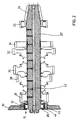
- Fig. 1 shows the front view of the bearing housing 10 of a group transmission for an agricultural tractor.
- a first bearing bore or bearing recess 12 and a second bearing recess 14 extend through the wall of the bearing housing 10.
- Rolling bearings 16, 18 are inserted into the bearing recesses 12, 14.
- the rollers 20 of the roller bearings 16 roll directly on the shaft raceway in the region of one of the ends of a gear shaft 22.
- the other end of the gear shaft 22 is supported by a combined radial and axial bearing, of which, however, only the radial part 23 has been indicated.
- the gear shaft 22 is the output shaft of a group transmission which has at one end a bevel gear 24 for driving the ring gear of a differential gear, not shown.
- the gear shaft 22 carries five gears 26, 28, 30, 32 and 34.
- the gears 26, 28, 30 and 32 can be selectively connected via gear sleeves with corresponding gears of a secondary shaft 36 not shown in the roller bearing 18, so that different ones Transmission ratios of the transmission are adjustable.
- the gear 34 is an output gear for the front wheel drive, not shown.
- the gear shaft 22 is radially loaded on one side by the respective tooth engagement of the gears 26, 28, 30, 32 and 34.
- the resulting loads and directions of force can be determined by a computer program. They can be different for each tooth mesh.
- a resulting direction of force was indicated by the arrow F in FIG. 1. It should be the main load direction, which is for the highest load of the bearing 16, taking into account different tooth engagements.
- the load on the shaft 22 leads to its deflection and misalignment on the bearings 16, 23.
- the resulting shaft inclination on the roller bearing 16 can be a few (for example 4) angular minutes.
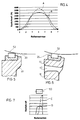
- the roller bearing 16 shown in FIG. 3 contains fourteen rollers that roll directly on a cylindrical bearing raceway of the gear shaft 22 and in a bearing outer ring 38. Because of the main direction of load F, a load is distributed to the rollers 1 to 7 according to the dashed line A in FIG. 4 for a conventionally designed, rigid bearing housing , which drops rapidly to the adjacent rolls 3, 2 and 1 or 5, 6 and 7.
- the housing stiffness of the bearing housing 10 according to FIG. 1 or 3 is reduced in the vicinity of the shaft bearing 16 in the direction of the main loading direction F.
- An increase in the housing compliance is achieved by an axial opening in the bearing housing, which in the exemplary embodiment described is designed as a semicircular groove 40 which extends through the entire shaft bearing wall thickness.
- the groove 40 has a constant radial width and extends concentrically around the shaft axis 42 over an angular range ⁇ of approximately 110 °.
- a web 44 of constant radial width S is formed between the groove 40 and the bearing outer ring 38.
- the width S of the web 44 should therefore be chosen as small as possible. However, for manufacturing reasons, it can be made of cast metal hardly less than 10 mm for vehicle transmission housings 10.
- the reduction in the load on the central roller 4 is 20% in the present example.
- the maximum roller load is decisive for the bearing life. Since the load on the rollers is provided with an exponent when calculating the service life, a 20% reduction in the load leads to an above-average increase in the bearing life, which in the present case is more than doubled in the present case.
- the variation of the opening angle ⁇ has a relatively small influence on the maximum roller force. It is therefore sensible to create the slot 40 so that all existing directions of force, which result from different tooth engagements of the shaft 22, are within the opening angle ⁇ of the slot 40. However, the opening angle ⁇ of the slot 40 should not exceed 130 °.
- Fig. 5 shows an arrangement with a conventional bearing housing 48 which is rigid.
- the rolling elements 20 only roll with an axial end region or their edges on the raceway 52 of the shaft 22. This leads to different loads on the rollers 20 in their axial direction, as was indicated by the dashed line C in FIG. 7.
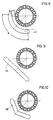
- FIGS. 8, 9 and 10 different slot shapes, through which a reduction in the housing rigidity in the direction of force can be achieved.
Landscapes
- Engineering & Computer Science (AREA)
- General Engineering & Computer Science (AREA)
- Mechanical Engineering (AREA)
- Rolling Contact Bearings (AREA)
Applications Claiming Priority (2)
| Application Number | Priority Date | Filing Date | Title |
|---|---|---|---|
| DE4406640A DE4406640A1 (de) | 1994-03-01 | 1994-03-01 | Lageranordnung zur Lagerung einer Welle |
| DE4406640 | 1994-03-01 |
Publications (1)
| Publication Number | Publication Date |
|---|---|
| EP0670432A2 true EP0670432A2 (fr) | 1995-09-06 |
Family
ID=6511507
Family Applications (1)
| Application Number | Title | Priority Date | Filing Date |
|---|---|---|---|
| EP95102306A Withdrawn EP0670432A2 (fr) | 1994-03-01 | 1995-02-18 | Montage de palier pour un arbre |
Country Status (2)
| Country | Link |
|---|---|
| EP (1) | EP0670432A2 (fr) |
| DE (1) | DE4406640A1 (fr) |
Cited By (1)
| Publication number | Priority date | Publication date | Assignee | Title |
|---|---|---|---|---|
| DE19961224B4 (de) * | 1999-11-27 | 2010-02-25 | Schaeffler Kg | Lagergehäuse |
Families Citing this family (7)
| Publication number | Priority date | Publication date | Assignee | Title |
|---|---|---|---|---|
| DE19543114A1 (de) * | 1995-11-18 | 1997-05-22 | Voith Sulzer Papiermasch Gmbh | Lagergehäuse zur Aufnahme von Wälzlagern |
| DE19617607B4 (de) * | 1996-05-02 | 2005-10-20 | Man B & W Diesel As Kopenhagen | Kurbelwellenlager für einen Großdieselmotor |
| DE10136821A1 (de) * | 2001-07-27 | 2003-02-06 | Bayerische Motoren Werke Ag | Metall-Trägerteil, insbesondere Fahrzeug-Achsträgerteil, mit einer angeschweissten Lagerbuchse |
| US6896491B2 (en) * | 2002-12-09 | 2005-05-24 | Caterpillar Inc | Bearing mounting flange having flexibility pocket |
| DE102007006226B4 (de) * | 2007-02-08 | 2016-07-21 | Zf Friedrichshafen Ag | Lagerbohrung |
| DE102010054567B4 (de) * | 2010-12-15 | 2015-08-20 | Rheinmetall Landsysteme Gmbh | Plastisch verformbare Lagerung |
| DE102011005761A1 (de) * | 2011-03-18 | 2012-09-20 | Schaeffler Technologies Gmbh & Co. Kg | Lageranordnung mit einem Fanglager |
Family Cites Families (6)
| Publication number | Priority date | Publication date | Assignee | Title |
|---|---|---|---|---|
| DE7711356U1 (fr) * | Gruenbaum, Heinrich, Binningen (Schweiz) | |||
| DE1525226A1 (de) * | 1965-10-08 | 1969-08-21 | Rheinstahl Henschel Ag | Wellenlager |
| DE2738287A1 (de) * | 1977-08-25 | 1979-03-01 | Schaeffler Ohg Industriewerk | Radial-axial-waelzlager |
| DE8424844U1 (de) * | 1984-08-22 | 1985-08-01 | Oexle, Friedrich, 7000 Stuttgart | Flanschlager |
| US4934838A (en) * | 1989-10-23 | 1990-06-19 | The Hamilton Tool Company | Frame member for supporting multiple bearings with heat barrier slot |
| DE4115217C2 (de) * | 1991-05-10 | 1993-10-21 | Deere & Co | Lagerungseinheit |
-
1994
- 1994-03-01 DE DE4406640A patent/DE4406640A1/de not_active Withdrawn
-
1995
- 1995-02-18 EP EP95102306A patent/EP0670432A2/fr not_active Withdrawn
Cited By (1)
| Publication number | Priority date | Publication date | Assignee | Title |
|---|---|---|---|---|
| DE19961224B4 (de) * | 1999-11-27 | 2010-02-25 | Schaeffler Kg | Lagergehäuse |
Also Published As
| Publication number | Publication date |
|---|---|
| DE4406640A1 (de) | 1995-11-16 |
Similar Documents
| Publication | Publication Date | Title |
|---|---|---|
| EP0518052B1 (fr) | Unité de palier | |
| DE3738521C1 (de) | Planetengetriebe | |
| DE60116504T2 (de) | Lagereinheit für radantrieb | |
| EP3405689B1 (fr) | Ensemble de palier | |
| DE69502550T2 (de) | Profilanpassung für Vielwalzengerüste | |
| EP2486305B1 (fr) | Train d'engrenage planetaire sans support | |
| EP0054280B1 (fr) | Transmission planétaire à engrenages droits | |
| DE102008053914A1 (de) | Wellengenerator für ein Spannungswellengetriebe sowie Spannungswellengetriebe | |
| DE2338686A1 (de) | Verfahren zur herstellung von rollenlagern | |
| EP1999388B2 (fr) | Boîte de vitesses à rondelle de compensation | |
| EP2126388A2 (fr) | Palier à roulement | |
| EP0670432A2 (fr) | Montage de palier pour un arbre | |
| WO2022179845A1 (fr) | Couronne pour un mécanisme de train planétaire | |
| DE2619019A1 (de) | Extrudergetriebe fuer achsparallel angeordnete, gegenlaufende doppelschnecken | |
| DE2123981A1 (de) | Rollenlager | |
| DE102014219705B4 (de) | Lagerring | |
| DE102004023151B4 (de) | Umlaufgetriebe | |
| EP1880123A1 (fr) | Roulement a galets coniques a quatre rangees | |
| DE3875242T2 (de) | Walze mit veraenderbarer balligkeit. | |
| WO2009059585A2 (fr) | Montage d'une roue planétaire pour optimiser la répartition des charges | |
| DE102019115309A1 (de) | Lagerscheibe für ein Axialrollenlager | |
| DE102017112924B4 (de) | Planetengetriebe | |
| DE102022124121A1 (de) | Wälzlager | |
| DE102017125331A1 (de) | Riemenantrieb | |
| DE60304566T2 (de) | Getriebe-einheit |
Legal Events
| Date | Code | Title | Description |
|---|---|---|---|
| PUAI | Public reference made under article 153(3) epc to a published international application that has entered the european phase |
Free format text: ORIGINAL CODE: 0009012 |
|
| AK | Designated contracting states |
Kind code of ref document: A2 Designated state(s): AT DE FR GB IT |
|
| STAA | Information on the status of an ep patent application or granted ep patent |
Free format text: STATUS: THE APPLICATION HAS BEEN WITHDRAWN |
|
| 18W | Application withdrawn |
Withdrawal date: 19960129 |