EP0670468A1 - Appareil de transmission de faisceau laser - Google Patents
Appareil de transmission de faisceau laser Download PDFInfo
- Publication number
- EP0670468A1 EP0670468A1 EP95301270A EP95301270A EP0670468A1 EP 0670468 A1 EP0670468 A1 EP 0670468A1 EP 95301270 A EP95301270 A EP 95301270A EP 95301270 A EP95301270 A EP 95301270A EP 0670468 A1 EP0670468 A1 EP 0670468A1
- Authority
- EP
- European Patent Office
- Prior art keywords
- housing
- transmitting apparatus
- laser beam
- base
- beam transmitting
- Prior art date
- Legal status (The legal status is an assumption and is not a legal conclusion. Google has not performed a legal analysis and makes no representation as to the accuracy of the status listed.)
- Granted
Links
- 230000003534 oscillatory effect Effects 0.000 claims abstract description 5
- 239000002184 metal Substances 0.000 claims description 11
- 229910052751 metal Inorganic materials 0.000 claims description 11
- XEEYBQQBJWHFJM-UHFFFAOYSA-N Iron Chemical compound [Fe] XEEYBQQBJWHFJM-UHFFFAOYSA-N 0.000 description 10
- 230000002093 peripheral effect Effects 0.000 description 9
- 229910052742 iron Inorganic materials 0.000 description 5
- 230000002238 attenuated effect Effects 0.000 description 2
- 230000005540 biological transmission Effects 0.000 description 2
- 230000005484 gravity Effects 0.000 description 2
- 230000003287 optical effect Effects 0.000 description 2
- RYGMFSIKBFXOCR-UHFFFAOYSA-N Copper Chemical compound [Cu] RYGMFSIKBFXOCR-UHFFFAOYSA-N 0.000 description 1
- 238000010276 construction Methods 0.000 description 1
- 229910052802 copper Inorganic materials 0.000 description 1
- 239000010949 copper Substances 0.000 description 1
- 230000000694 effects Effects 0.000 description 1
- 239000011521 glass Substances 0.000 description 1
- 230000001681 protective effect Effects 0.000 description 1
Images




Classifications
-
- G—PHYSICS
- G01—MEASURING; TESTING
- G01C—MEASURING DISTANCES, LEVELS OR BEARINGS; SURVEYING; NAVIGATION; GYROSCOPIC INSTRUMENTS; PHOTOGRAMMETRY OR VIDEOGRAMMETRY
- G01C15/00—Surveying instruments or accessories not provided for in groups G01C1/00 - G01C13/00
- G01C15/002—Active optical surveying means
- G01C15/004—Reference lines, planes or sectors
-
- G—PHYSICS
- G01—MEASURING; TESTING
- G01C—MEASURING DISTANCES, LEVELS OR BEARINGS; SURVEYING; NAVIGATION; GYROSCOPIC INSTRUMENTS; PHOTOGRAMMETRY OR VIDEOGRAMMETRY
- G01C15/00—Surveying instruments or accessories not provided for in groups G01C1/00 - G01C13/00
- G01C15/10—Plumb lines
- G01C15/105—Optical plumbing
-
- Y—GENERAL TAGGING OF NEW TECHNOLOGICAL DEVELOPMENTS; GENERAL TAGGING OF CROSS-SECTIONAL TECHNOLOGIES SPANNING OVER SEVERAL SECTIONS OF THE IPC; TECHNICAL SUBJECTS COVERED BY FORMER USPC CROSS-REFERENCE ART COLLECTIONS [XRACs] AND DIGESTS
- Y10—TECHNICAL SUBJECTS COVERED BY FORMER USPC
- Y10S—TECHNICAL SUBJECTS COVERED BY FORMER USPC CROSS-REFERENCE ART COLLECTIONS [XRACs] AND DIGESTS
- Y10S33/00—Geometrical instruments
- Y10S33/21—Geometrical instruments with laser
Definitions
- This invention relates to a laser beam transmitting apparatus for use in construction and civil engineering industries, and particularly to a laser beam transmitting apparatus for use for levelling using a laser beam and marking work along a horizontal plane or a vertical plane.
- This laser beam level instrument converts light from a light source such as an He-Ne gas laser or a laser diode into a substantially collimated beam by an optical system having a collimator lens, and causes the beam to emerge in a horizontal direction by way of a rotatable mirror, thereby supplying a beam of light swept on a horizontal plane.
- a light source such as an He-Ne gas laser or a laser diode
- This laser beam level instrument converts light from a light source such as an He-Ne gas laser or a laser diode into a substantially collimated beam by an optical system having a collimator lens, and causes the beam to emerge in a horizontal direction by way of a rotatable mirror, thereby supplying a beam of light swept on a horizontal plane.
- a cylindrical inner housing 103 holding a collimator lens 105 is suspended from a beam transmitting unit 101 by means of three wires 102.
- the inner housing 103 is contained in a cylindrical fixed housing 104 fixed to the beam transmitting unit 101, and the outer peripheral surface of the inner housing 103 is spaced apart by a minute distance d from the inner peripheral surface of the fixed housing 104 and has the function of automatically correcting inclination within this range.
- a light source 111 emitting a beam of light L is disposed substantially at the focal position of the collimator lens 105.
- a cylindrical rotatable member 114 is disposed below the collimator lens 105, and the rotatable member 114 is rotatably mounted on the beam transmitting unit 101 through a bearing 116.
- a pair of mirrors 115 for reflecting the beam of light L from the collimator lens 105 at a right angle are fixed to the interior of the rotatable member 114.
- the rotatable member 114 is rotated by a motor 110 through a transmission belt 118.
- the beam of light L reflected by the pair of mirrors 115 is caused to emerge outwardly through windows 114a and 101a and is swept in the direction of 360° in a horizontal plane.
- the beam transmitting unit 101 is placed on a levelling unit 130.
- the levelling unit 130 comprises an upper plate 131 fixed to the beam transmitting unit 101, and a lower plate 132 mounted on the upper plate 131 through three levelling screws 133.
- the lower plate 132 is connected to a tripod.
- a bubble tube 134 is fixed to the upper plate 131.
- the operator When installing the apparatus through the tripod, the operator turns the levelling screws 133 while watching the bubble tube 134 and effects rough levelling work. By this work, the operator can correct inclination up to the order of ⁇ 10' (minutes).
- the manual levelling work by the operator is done, precise level accuracy within ⁇ 10'' (seconds) is achieved by the above-described automatic inclination correction work of the inner housing 103.
- the range within which the precise levelling by the automatic inclination correction is possible is as small as several tens of minutes and therefore, the levelling work of turning the levelling screws 133 while watching the positions of bubbles in the bubble tube 134 has required skill and has been practically cumbersome to the operator, and has taken much time until levelling is done up to an angle of several tens of minutes. Accordingly, when the laser beam transmitting apparatus is frequently moved for use, the burden of the operator has become greater, thus resulting in the aggravation of work efficiency.
- the laser beam transmitting apparatus of the present invention is provided with a base, a beam transmitter for supplying a beam of light, a housing for holding the beam transmitter, and a levelling mechanism provided between the housing and the base, the housing being oscillatably supported on the base and the center of oscillatory movement thereof being positioned above the centroid of the housing.
- the laser beam transmitting apparatus of the present invention is provided with a precise levelling mechanism between the beam transmitter and the housing, whereby it can accomplish double levelling combined with the rough levelling function by the levelling mechanism between the housing and the base.
- a concave spherical inner wall surface for receiving the housing is provided on the base, and a bearing device is provided between the housing and the spherical inner wall surface.
- the centroid of the housing is positioned below the center of curvature of the spherical inner wall surface.
- a vibration attenuator is provided between the housing and the base. Gimbal structure may be used as the rough levelling mechanism.
- an outer case having an upper surface portion, an outer housing oscillatably suspended from the upper surface portion of the outer case, and an inner housing holding the beam transmitter and oscillatably suspended from the outer housing.
- Figure 1 is a vertical cross-sectional view of a laser beam transmitting apparatus according to the prior art.
- Figure 2 is a vertical cross-sectional view of a laser beam transmitting apparatus according to a first embodiment of the present invention.
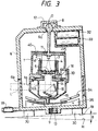
- Figure 3 is a vertical cross-sectional view showing a state in which the apparatus of Figure 2 is inclined.
- Figure 4 is a vertical cross-sectional view of a laser beam transmitting apparatus according to a second embodiment of the present invention.
- Figure 5 is a vertical cross-sectional view showing a state in which the apparatus of Figure 4 is inclined.
- Figure 6 is a vertical cross-sectional view of a laser beam transmitting apparatus according to a third embodiment of the present invention.
- Figure 7 is a plan view showing the structure of a magnet.
- Figure 8 is a cross-sectional view taken along the line 8-8 of Figure 7.
- An outer housing 1 is oscillatably suspended in an outer case 6 through a rough levelling mechanism.
- An arm 7 is integrally provided on the upper end portion of the outer housing 1, and a sphere portion 8 is integrally provided on the tip end portion of the arm 7.
- a spherical non-magnetic metal plate 9 (e.g. a copper plate) is fixed to the lower end portion of the outer housing 1 by means of a screw 37.
- the upper surface portion of the outer case 6 constitutes a base for supporting the outer housing 1 and is formed with a spherical bearing 6a for rotatably supporting the sphere portion 8. Also, the upper surface portion of the outer case 6 has mounted thereon a lid 12 covering the sphere portion 8.
- the lower portion of the outer case 6 is formed with a window 6b for transmitting a laser beam outwardly therethrough, and protective glass 36 is mounted in the window 6b.
- An internally threaded portion 13 for mounting the outer case 6 on a tripod, not shown, and three contact portions 30 bearing against the reference surface of the tripod are integrally provided on the lower surface portion of the outer case 6.
- a battery box 33 containing therein a battery 32 for supplying electric power to a laser diode 11 and a circuit base plate 40 fixed to the outer housing 1 is provided in the upper portion of the outer case 6.
- Spherical magnets 34 and 35 are disposed in the lower portion of the outer case 6.
- the magnet 34 is located above the non-magnetic metal plate 9, and the magnet 35 differing in polarity from the magnet 34 is located below the non-magnetic metal plate 9.
- the centers of curvature of the spherical non-magnetic plate 9 and the spherical magnets 34, 35 are coincident with the center of oscillatory movement of the outer housing 1 (the center O of the sphere portion 8).
- the non-magnetic metal plate 9 and the magnets 34, 35 together constitute a vibration attenuating mechanism of the magnetic type.
- a cylindrical inner housing 3 holding a collimator lens 5 is suspended in the outer housing 1 by means of three wires 2 to thereby constitute a precise levelling mechanism similar to that disclosed in U.S. Patent No. 4,221,483.
- the inner housing 3 is contained in a cylindrical fixed housing 4 fixed to the outer housing 1 and the outer peripheral surface of the inner housing 3 is spaced apart by a minute distance d from the inner peripheral surface of the fixed housing 4.
- the fixed housing 4 and the inner housing 3 contained in the fixed housing 4 together constitute a vibration attenuating mechanism of the air damper type.
- the laser diode 11 emitting a beam of light L is disposed substantially at the focal position of the collimator lens 5.
- a cylindrical rotatable member 14 is disposed below the collimator lens 5 and the rotatable member 14 is rotatably mounted in the outer housing 1 through a bearing 16.
- a pair of mirrors 15 for reflecting the beam of light L from the collimator lens 5 at a light angle are fixed to the interior of the rotatable member 14.
- the rotatable member 14 is rotatable by a motor 10 through a transmission belt, not shown.
- the operation of the laser beam transmitting apparatus of this embodiment will now be described.
- An operator first installs the laser beam transmitting apparatus at a predetermined location through the tripod, and sets it roughly (within ⁇ 10°) while watching a bubble tube 18.
- this rough levelling mechanism the angle of inclination of about 10° is automatically corrected within 8'.
- the vibration of the outer housing 1 is attenuated by an eddy current generated when the non-magnetic metal plate 9 crosses the magnetic field formed between the magnets 34 and 35.
- the outer housing 1 leaves an inclination within 8' with respect to the direction of gravity, but this inclination is further corrected by the precise levelling mechanism. That is, the three wires suspending the inner housing 3 always try to maintain verticality and therefore, they are parallel-moved in a substantially horizontal direction by the outer housing 1 being inclined. Thus, the collimator lens 5 is always vibrated back to just beneath the laser diode 11 in a vertical direction, and irrespective of the inclination of the outer housing 1, the laser beam L is always directed vertically downwardly. As a result of this precise levelling, correction accuracy within ⁇ 10'' is obtained.
- the slight spacing d between the outer peripheral surface of the inner housing 3 and the inner peripheral surface of the fixed housing 4 is varied by the relative vibration between the outer housing 1 and the inner housing 3.
- the relative vibration is attenuated by the flow resistance of air produced at that time.
- the beam of light L from the laser diode 11 is collimated by the collimator lens 5 and is reflected in a horizontal direction by the pair of mirrors 15.
- the beam of light L is caused to emerge outwardly through the windows 4a, 1a and 6b, and is swept in the direction of 360° in a horizontal plane.
- a hollow arm 57 is integrally provided on the upper end portion of an outer housing 51
- a semispherical body 58 is threadably coupled to the tip end portion of the arm 57
- a battery box 53 is integrally provided on the semispherical body 58.
- a spherical bearing 56a is formed on the upper portion of an outer case 56. The spherical surface 58a of the semispherical body 58 is supported through at least three balls 50 rollably provided in the inner wall of the spherical bearing 56a.
- a vibration attenuating mechanism of the magnetic type having an annular non-magnetic metal plate 41 fixed to the lower portion of the inner housing 3, and magnets 42 and 43 disposed above and below it and differing in polarity from each other.
- the relation between the collimator lens and the laser diode may be reversed and the light source may be suspended by means of wires.
- the optical element provided between the light source and the collimator lens so as to be suspended.
- the beam of light emitted from the laser beam transmitting apparatus be not necessarily swept in a horizontal plane. That is, the present invention is also applicable to a laser beam transmitting apparatus simply emitting a beam of light in a predetermined direction.
- Figure 6 shows an embodiment of a laser beam transmitting apparatus emitting a beam of light in a vertical direction, and this embodiment is provided with an outer case 61 and a hollow housing 62 suspended in the outer case 61.
- the outer case 61 has a barrel-shaped base 63, a barrel-shaped upper case 64 placed on the base 63, and a cap 65 threadably engaged with the upper end of the upper case 64.
- a magnet 66 for fixing the apparatus to the ceiling is provided on the upper surface of the cap 65, and a spherical-surfaced magnet 67 is provided on the lower surface of the cap 65. As shown in Figures 7 and 8, the magnet 67 has magnetic poles of different polarities alternately magnetized in the radial direction thereof.
- a magnet 82 for fixing the outer case 61 to an iron post 68 is provided on the outer peripheral surface of the base 63.
- a sliding bearing 69 for oscillatably supporting the housing 62 is provided on the inner peripheral surface of the upper portion of the base 63 to constitute a rough levelling mechanism.
- This bearing 69 may be replaced by gimbal structure.
- An electrically conductive resilient ring 70 is provided below the sliding bearing 69.
- a lid 71 formed of a non-magnetic metal is mounted on the upper end of the housing 62, and the upper surface of the lid 71 is formed into a spherical surface.
- the centers of curvature of the spherical surface of the lid 71 and the spherical surface of the magnet 67 coincide with the center of oscillatory movement O of the housing 62, and they always keep a constant spacing d.
- a cylindrical inner housing 73 holding a collimator lens 72 is suspended from the lower portion of the housing 62 by means of three wires 74 to constitute a precise levelling mechanism similar to that in the aforedescribed embodiment.
- the inner housing 73 is contained in a cylindrical fixed housing 75 fixed to the lower portion of the housing 62, and an air damper is formed between the two housings.
- a laser diode 76 emitting a beam of visible light L is disposed substantially at the focal position of the collimator lens 72.
- the interior of the housing 62 is divided into two containing chambers 62a and 62b, and a control circuit 77 for driving the light source is disposed in the containing chamber 62a, and a battery 83 is contained in the containing chamber 62b.
- a pair of annular electrical contacts 78 and 79 insulated from each other are disposed on the outer peripheral surface of the housing 62.
- the resilient ring 70 and the electrical contacts 78, 79 contact with each other when the housing 62 is inclined by a predetermined angle C or greater from a reference position, whereby electrical conduction takes place between the electrical contacts 78 and 79.
- the control circuit 77 detects this conduction and turns on and off or turns off the laser diode 76, thereby informing that the laser beam transmitting apparatus is installed in an unsuitable posture.
- the apparatus of this third embodiment is used to install, for example, the iron post 68 exactly vertically. That is, the apparatus can be fixed to the iron post 68 stood on a floor surface 84 and the beam of light can be transmitted toward the floor surface, and the inclination of the iron post can be adjusted so that the distance from the lower end of the iron post 68 to the position of the light spot on the floor surface may coincide with a reference distance.
Landscapes
- Physics & Mathematics (AREA)
- Engineering & Computer Science (AREA)
- General Physics & Mathematics (AREA)
- Radar, Positioning & Navigation (AREA)
- Remote Sensing (AREA)
- Lasers (AREA)
Applications Claiming Priority (4)
| Application Number | Priority Date | Filing Date | Title |
|---|---|---|---|
| JP54853/94 | 1994-03-01 | ||
| JP6054853A JPH07243855A (ja) | 1994-03-01 | 1994-03-01 | 可視光ビームの投光装置 |
| JP67671/94 | 1994-03-11 | ||
| JP06767194A JP3435788B2 (ja) | 1994-03-11 | 1994-03-11 | レーザ投光装置 |
Publications (2)
| Publication Number | Publication Date |
|---|---|
| EP0670468A1 true EP0670468A1 (fr) | 1995-09-06 |
| EP0670468B1 EP0670468B1 (fr) | 1999-04-28 |
Family
ID=26395672
Family Applications (1)
| Application Number | Title | Priority Date | Filing Date |
|---|---|---|---|
| EP95301270A Expired - Lifetime EP0670468B1 (fr) | 1994-03-01 | 1995-02-28 | Appareil de transmission de faisceau laser |
Country Status (3)
| Country | Link |
|---|---|
| US (1) | US5552886A (fr) |
| EP (1) | EP0670468B1 (fr) |
| DE (1) | DE69509289T2 (fr) |
Cited By (4)
| Publication number | Priority date | Publication date | Assignee | Title |
|---|---|---|---|---|
| WO2006044022A1 (fr) * | 2004-10-19 | 2006-04-27 | Trimble Navigation Limited | Outil d'alignement equipe d'un laser a nivellement automatique et procede associe |
| US7155835B2 (en) | 2004-07-19 | 2007-01-02 | Trimble Navigation Limited | Self-leveling laser alignment tool and method thereof which compensates for material stiffness of an included pendulum |
| EP1852677A2 (fr) | 1996-09-10 | 2007-11-07 | Black & Decker, Inc. | Outil de référence de lumineuse laser |
| WO2008119583A1 (fr) * | 2007-03-29 | 2008-10-09 | Robert Bosch Gmbh | Dispositif de marquage, système de marquage et procédé de manipulation d'un système de marquage de ce type |
Families Citing this family (42)
| Publication number | Priority date | Publication date | Assignee | Title |
|---|---|---|---|---|
| IT1275249B (it) * | 1995-02-22 | 1997-07-31 | Micro Italiana Spa | Dispositivo proiettore di uno o piu' fasci piani di raggi laser divergenti autolivellante a gravita' per la proiezione di una o piu' rette orizzontali e/o verticali su corpi del tipo parete o simili |
| USD399145S (en) | 1997-08-12 | 1998-10-06 | Ko-Liang Ho | Laser indicator |
| US5914778A (en) * | 1998-06-01 | 1999-06-22 | Dong; Dawei | Automatic laser level |
| DE50007989D1 (de) * | 1999-01-19 | 2004-11-04 | Leica Geosystems Ag | Anordnung zur bestimmung der höhenlage eines geodätischen instruments |
| US6338681B1 (en) * | 2000-06-09 | 2002-01-15 | Aurise Inc. | Magnetic transmission structure |
| US6668466B1 (en) * | 2000-10-19 | 2003-12-30 | Sandia Corporation | Highly accurate articulated coordinate measuring machine |
| TW463943U (en) * | 2001-01-12 | 2001-11-11 | Wu Chi Ying | Full-angle automatic calibrated light emitting device |
| US7278218B2 (en) | 2003-06-18 | 2007-10-09 | Irwin Industrial Tool Company | Laser line generating device with swivel base |
| EP1393016A4 (fr) | 2001-05-15 | 2007-03-21 | American Tool Comp Inc | Dispositif de generation d'une ligne laser |
| TW491349U (en) * | 2001-08-10 | 2002-06-11 | Quarton Inc | Projection device for laser spot line |
| TW524308U (en) * | 2001-08-10 | 2003-03-11 | Quarton Inc | Projection labeling device |
| US6625895B2 (en) * | 2001-12-04 | 2003-09-30 | Toolz, Ltd. | Servo-controlled automatic level and plumb tool |
| AU2002351189A1 (en) * | 2001-12-04 | 2003-06-17 | Toolz, Ltd. | Alignment device |
| US6871408B2 (en) * | 2002-03-01 | 2005-03-29 | Irwin Industrial Tool Company | Manual leveling rotating laser with swivel head |
| US6763596B1 (en) | 2002-08-23 | 2004-07-20 | Chicago Steel Tape Co. | Laser alignment device |
| US6938350B1 (en) * | 2002-12-31 | 2005-09-06 | PLS—Pacific Laser Systems | Apparatus for producing a reference plane |
| US6804892B1 (en) * | 2003-03-28 | 2004-10-19 | Toolz, Ltd | Alignment device with multiple spring systems |
| US7013570B2 (en) | 2003-06-18 | 2006-03-21 | Irwin-Industrial Tool Company | Stud finder |
| US7269907B2 (en) | 2003-07-01 | 2007-09-18 | Irwin Industrial Tool Company | Laser line generating device with swivel base |
| EP1528311A3 (fr) * | 2003-11-03 | 2005-08-17 | BLACK & DECKER INC. | Trépied |
| US7762684B2 (en) * | 2003-12-12 | 2010-07-27 | Jeffrey Dale Wilson | Hand-held stabilized laser pointer |
| TWI354773B (en) * | 2004-02-13 | 2011-12-21 | Black & Decker Inc | Two wire circuit for a laser pendulum |
| US7134211B2 (en) | 2004-03-18 | 2006-11-14 | Black & Decker Inc. | Laser level |
| CN2718518Y (zh) * | 2004-06-18 | 2005-08-17 | 南京德朔实业有限公司 | 激光标线器 |
| US7487596B2 (en) | 2004-06-25 | 2009-02-10 | Irwin Industrial Tool Company | Laser line projected on an edge of a surface |
| US7178250B2 (en) | 2004-07-21 | 2007-02-20 | Irwin Industrial Tool Company | Intersecting laser line generating device |
| US7181854B2 (en) | 2004-08-17 | 2007-02-27 | Eastway Fair Company Limited | Laser leveling device having a suction mounting arrangement |
| US7191532B2 (en) | 2004-08-17 | 2007-03-20 | Eastway Fair Company Limited | Modular tool assembly having a vacuum mounting arrangement |
| US7497019B2 (en) | 2005-08-04 | 2009-03-03 | Irwin Industrial Tool Company | Laser reference device |
| US7328516B2 (en) * | 2005-08-05 | 2008-02-12 | Irwin Industrial Tool Company | Laser level |
| US7497018B2 (en) | 2006-05-26 | 2009-03-03 | William Hersey | Laser-based alignment tool |
| US7591075B2 (en) | 2006-09-28 | 2009-09-22 | Techtronic Power Tools Technology Limited | Self-leveling mechanism |
| US7861424B2 (en) * | 2006-11-13 | 2011-01-04 | Robert Bosch Tool Corporation | Pipe laser |
| JP5103004B2 (ja) * | 2006-11-15 | 2012-12-19 | 株式会社トプコン | レーザ測量機 |
| USD571237S1 (en) | 2006-12-20 | 2008-06-17 | Pls-Pacific Laser Systems, Llc | Laser level detector |
| DE102008041033A1 (de) * | 2008-08-06 | 2010-02-11 | Hilti Aktiengesellschaft | Rotationsbaulaser |
| US7841094B2 (en) * | 2009-01-27 | 2010-11-30 | Trimble Kaiserslautern Gmbh | Optical instrument with angle indicator and method for operating the same |
| DE102010042430B4 (de) * | 2010-10-14 | 2017-01-26 | Robert Bosch Gmbh | Markierungslichtvorrichtung zum Erzeugen einer Standardlichtebene |
| US9441967B2 (en) | 2013-05-31 | 2016-09-13 | Stanley Black & Decker Inc. | Laser level system |
| US10184794B2 (en) * | 2015-07-01 | 2019-01-22 | Makita Corporation | Laser marker |
| JP2019012105A (ja) * | 2017-06-29 | 2019-01-24 | 日本電産株式会社 | ケーシングユニット |
| CN113464812B (zh) * | 2021-07-06 | 2023-03-21 | 中纬地理信息技术有限公司 | 一种激光雷达测绘装置及减震组件 |
Citations (5)
| Publication number | Priority date | Publication date | Assignee | Title |
|---|---|---|---|---|
| US4221483A (en) * | 1978-11-20 | 1980-09-09 | Spectra-Physics, Inc. | Laser beam level instrument |
| GB2200474A (en) * | 1987-01-20 | 1988-08-03 | Sokkisha | Optical level-defining apparatus |
| EP0297601A2 (fr) * | 1987-07-02 | 1989-01-04 | Spectra Precision, Inc. | Emetteur auto-niveleur pour systèmes d'alignement à laser |
| WO1990013002A1 (fr) * | 1989-04-14 | 1990-11-01 | Bruce George Key | Dispositif pour definir un plan horizontal |
| US5144487A (en) * | 1991-09-03 | 1992-09-01 | Pacific Laser | Portable laser device for alignment tasks |
-
1995
- 1995-02-27 US US08/394,815 patent/US5552886A/en not_active Expired - Lifetime
- 1995-02-28 EP EP95301270A patent/EP0670468B1/fr not_active Expired - Lifetime
- 1995-02-28 DE DE69509289T patent/DE69509289T2/de not_active Expired - Fee Related
Patent Citations (6)
| Publication number | Priority date | Publication date | Assignee | Title |
|---|---|---|---|---|
| US4221483A (en) * | 1978-11-20 | 1980-09-09 | Spectra-Physics, Inc. | Laser beam level instrument |
| US4221483B1 (fr) * | 1978-11-20 | 1991-08-13 | Spectra Physics | |
| GB2200474A (en) * | 1987-01-20 | 1988-08-03 | Sokkisha | Optical level-defining apparatus |
| EP0297601A2 (fr) * | 1987-07-02 | 1989-01-04 | Spectra Precision, Inc. | Emetteur auto-niveleur pour systèmes d'alignement à laser |
| WO1990013002A1 (fr) * | 1989-04-14 | 1990-11-01 | Bruce George Key | Dispositif pour definir un plan horizontal |
| US5144487A (en) * | 1991-09-03 | 1992-09-01 | Pacific Laser | Portable laser device for alignment tasks |
Cited By (10)
| Publication number | Priority date | Publication date | Assignee | Title |
|---|---|---|---|---|
| EP1852677A2 (fr) | 1996-09-10 | 2007-11-07 | Black & Decker, Inc. | Outil de référence de lumineuse laser |
| EP1852678A2 (fr) | 1996-09-10 | 2007-11-07 | BLACK & DECKER INC. | Outil de référence de lumière laser |
| EP1852677A3 (fr) * | 1996-09-10 | 2007-11-21 | Black & Decker, Inc. | Outil de référence de lumineuse laser |
| EP1852678A3 (fr) * | 1996-09-10 | 2007-11-28 | BLACK & DECKER INC. | Outil de référence de lumière laser |
| US7155835B2 (en) | 2004-07-19 | 2007-01-02 | Trimble Navigation Limited | Self-leveling laser alignment tool and method thereof which compensates for material stiffness of an included pendulum |
| WO2006044022A1 (fr) * | 2004-10-19 | 2006-04-27 | Trimble Navigation Limited | Outil d'alignement equipe d'un laser a nivellement automatique et procede associe |
| US7073269B2 (en) | 2004-10-19 | 2006-07-11 | Trimble Navigation Limited | Self-leveling laser alignment tool and method thereof |
| CN100575875C (zh) * | 2004-10-19 | 2009-12-30 | 天宝导航有限公司 | 自调平激光对准工具及其方法 |
| DE112005002506B4 (de) * | 2004-10-19 | 2010-02-11 | Trimble Navigation Ltd., Sunnyvale | Selbstnivellierendes Laser-Ausrichtungswerkzeug und Verfahren davon |
| WO2008119583A1 (fr) * | 2007-03-29 | 2008-10-09 | Robert Bosch Gmbh | Dispositif de marquage, système de marquage et procédé de manipulation d'un système de marquage de ce type |
Also Published As
| Publication number | Publication date |
|---|---|
| DE69509289T2 (de) | 1999-08-19 |
| DE69509289D1 (de) | 1999-06-02 |
| US5552886A (en) | 1996-09-03 |
| EP0670468B1 (fr) | 1999-04-28 |
Similar Documents
| Publication | Publication Date | Title |
|---|---|---|
| US5552886A (en) | Laser beam transmitting apparatus | |
| US4993161A (en) | Laser beam level instrument | |
| US3936197A (en) | Self-leveling laser assembly | |
| US5917587A (en) | Automatic plumb laser beam generator | |
| US5481809A (en) | Laser plumb bob and apparatus | |
| US5572796A (en) | Laser beam pendular level | |
| JP3034606B2 (ja) | アライメント作業用携帯型レーザ装置 | |
| US6625895B2 (en) | Servo-controlled automatic level and plumb tool | |
| US6763595B1 (en) | Laser-based tool for indicating level, plumb and square | |
| EP1681534B1 (fr) | Niveau de laser | |
| EP0715707B1 (fr) | Outil automatique de mise a niveau et d'aplomb | |
| JPH0127045Y2 (fr) | ||
| EP2029965B1 (fr) | Outil d'alignement à laser | |
| EP0223043B1 (fr) | Emetteur à nivellement automatique pour système d'alignement à laser | |
| US5572797A (en) | Improved optical plumb and leveling apparatus | |
| US6938350B1 (en) | Apparatus for producing a reference plane | |
| EP0888524A1 (fr) | Dispositif d'evaluation par laser, oriente par gravite | |
| US5805362A (en) | Focusing mechanism using a thin diaphragm | |
| JP2000258160A (ja) | 改良された運搬可能な自動的に水平姿勢を取るレーザ光線装置 | |
| US6722048B2 (en) | Laser projection apparatus for point and line | |
| JP3435788B2 (ja) | レーザ投光装置 | |
| US3988837A (en) | Optical plumbing device | |
| US20120019911A1 (en) | Device for Stabilizing a Light Beam or Images | |
| JPH07243855A (ja) | 可視光ビームの投光装置 | |
| GB1565838A (en) | Portable axis definition apparatus |
Legal Events
| Date | Code | Title | Description |
|---|---|---|---|
| PUAI | Public reference made under article 153(3) epc to a published international application that has entered the european phase |
Free format text: ORIGINAL CODE: 0009012 |
|
| AK | Designated contracting states |
Kind code of ref document: A1 Designated state(s): CH DE FR GB IT LI NL SE |
|
| 17P | Request for examination filed |
Effective date: 19960229 |
|
| 17Q | First examination report despatched |
Effective date: 19971014 |
|
| GRAG | Despatch of communication of intention to grant |
Free format text: ORIGINAL CODE: EPIDOS AGRA |
|
| GRAG | Despatch of communication of intention to grant |
Free format text: ORIGINAL CODE: EPIDOS AGRA |
|
| GRAH | Despatch of communication of intention to grant a patent |
Free format text: ORIGINAL CODE: EPIDOS IGRA |
|
| GRAH | Despatch of communication of intention to grant a patent |
Free format text: ORIGINAL CODE: EPIDOS IGRA |
|
| GRAA | (expected) grant |
Free format text: ORIGINAL CODE: 0009210 |
|
| AK | Designated contracting states |
Kind code of ref document: B1 Designated state(s): CH DE FR GB IT LI NL SE |
|
| PG25 | Lapsed in a contracting state [announced via postgrant information from national office to epo] |
Ref country code: SE Free format text: THE PATENT HAS BEEN ANNULLED BY A DECISION OF A NATIONAL AUTHORITY Effective date: 19990428 Ref country code: LI Free format text: LAPSE BECAUSE OF FAILURE TO SUBMIT A TRANSLATION OF THE DESCRIPTION OR TO PAY THE FEE WITHIN THE PRESCRIBED TIME-LIMIT Effective date: 19990428 Ref country code: FR Free format text: LAPSE BECAUSE OF FAILURE TO SUBMIT A TRANSLATION OF THE DESCRIPTION OR TO PAY THE FEE WITHIN THE PRESCRIBED TIME-LIMIT Effective date: 19990428 Ref country code: CH Free format text: LAPSE BECAUSE OF FAILURE TO SUBMIT A TRANSLATION OF THE DESCRIPTION OR TO PAY THE FEE WITHIN THE PRESCRIBED TIME-LIMIT Effective date: 19990428 |
|
| REG | Reference to a national code |
Ref country code: CH Ref legal event code: EP |
|
| REF | Corresponds to: |
Ref document number: 69509289 Country of ref document: DE Date of ref document: 19990602 |
|
| EN | Fr: translation not filed | ||
| REG | Reference to a national code |
Ref country code: CH Ref legal event code: PL |
|
| PLBE | No opposition filed within time limit |
Free format text: ORIGINAL CODE: 0009261 |
|
| STAA | Information on the status of an ep patent application or granted ep patent |
Free format text: STATUS: NO OPPOSITION FILED WITHIN TIME LIMIT |
|
| 26N | No opposition filed | ||
| REG | Reference to a national code |
Ref country code: GB Ref legal event code: IF02 |
|
| PGFP | Annual fee paid to national office [announced via postgrant information from national office to epo] |
Ref country code: NL Payment date: 20030226 Year of fee payment: 9 Ref country code: GB Payment date: 20030226 Year of fee payment: 9 |
|
| PGFP | Annual fee paid to national office [announced via postgrant information from national office to epo] |
Ref country code: DE Payment date: 20030313 Year of fee payment: 9 |
|
| PG25 | Lapsed in a contracting state [announced via postgrant information from national office to epo] |
Ref country code: GB Free format text: LAPSE BECAUSE OF NON-PAYMENT OF DUE FEES Effective date: 20040228 |
|
| PG25 | Lapsed in a contracting state [announced via postgrant information from national office to epo] |
Ref country code: NL Free format text: LAPSE BECAUSE OF NON-PAYMENT OF DUE FEES Effective date: 20040901 Ref country code: DE Free format text: LAPSE BECAUSE OF NON-PAYMENT OF DUE FEES Effective date: 20040901 |
|
| GBPC | Gb: european patent ceased through non-payment of renewal fee | ||
| NLV4 | Nl: lapsed or anulled due to non-payment of the annual fee |
Effective date: 20040901 |
|
| PG25 | Lapsed in a contracting state [announced via postgrant information from national office to epo] |
Ref country code: IT Free format text: LAPSE BECAUSE OF NON-PAYMENT OF DUE FEES Effective date: 20050228 |