EP0670512A1 - Rétroprojecteur pour la projection d'images affichés sur des cristaux liquides - Google Patents
Rétroprojecteur pour la projection d'images affichés sur des cristaux liquides Download PDFInfo
- Publication number
- EP0670512A1 EP0670512A1 EP94103934A EP94103934A EP0670512A1 EP 0670512 A1 EP0670512 A1 EP 0670512A1 EP 94103934 A EP94103934 A EP 94103934A EP 94103934 A EP94103934 A EP 94103934A EP 0670512 A1 EP0670512 A1 EP 0670512A1
- Authority
- EP
- European Patent Office
- Prior art keywords
- lcd
- electronics
- overhead projector
- space
- metal vapor
- Prior art date
- Legal status (The legal status is an assumption and is not a legal conclusion. Google has not performed a legal analysis and makes no representation as to the accuracy of the status listed.)
- Withdrawn
Links
- 239000002184 metal Substances 0.000 claims abstract description 36
- 238000009413 insulation Methods 0.000 claims abstract description 4
- 229910001507 metal halide Inorganic materials 0.000 claims description 25
- 150000005309 metal halides Chemical class 0.000 claims description 25
- 238000001816 cooling Methods 0.000 claims description 7
- 238000005192 partition Methods 0.000 claims description 6
- 230000005855 radiation Effects 0.000 claims description 4
- 239000011521 glass Substances 0.000 abstract description 3
- 239000003570 air Substances 0.000 description 26
- 239000004973 liquid crystal related substance Substances 0.000 description 7
- 238000004880 explosion Methods 0.000 description 6
- 230000004308 accommodation Effects 0.000 description 2
- 230000000694 effects Effects 0.000 description 2
- 238000009423 ventilation Methods 0.000 description 2
- 206010057040 Temperature intolerance Diseases 0.000 description 1
- 239000012080 ambient air Substances 0.000 description 1
- 230000005540 biological transmission Effects 0.000 description 1
- 239000013078 crystal Substances 0.000 description 1
- 229910052736 halogen Inorganic materials 0.000 description 1
- 150000002367 halogens Chemical class 0.000 description 1
- 230000008543 heat sensitivity Effects 0.000 description 1
- 238000010438 heat treatment Methods 0.000 description 1
- 238000000926 separation method Methods 0.000 description 1
- 239000013585 weight reducing agent Substances 0.000 description 1
Images




Classifications
-
- G—PHYSICS
- G03—PHOTOGRAPHY; CINEMATOGRAPHY; ANALOGOUS TECHNIQUES USING WAVES OTHER THAN OPTICAL WAVES; ELECTROGRAPHY; HOLOGRAPHY
- G03B—APPARATUS OR ARRANGEMENTS FOR TAKING PHOTOGRAPHS OR FOR PROJECTING OR VIEWING THEM; APPARATUS OR ARRANGEMENTS EMPLOYING ANALOGOUS TECHNIQUES USING WAVES OTHER THAN OPTICAL WAVES; ACCESSORIES THEREFOR
- G03B21/00—Projectors or projection-type viewers; Accessories therefor
- G03B21/132—Overhead projectors, i.e. capable of projecting hand-writing or drawing during action
Definitions
- the invention relates to an overhead projector for the projection of images displayed by means of an LCD, consisting of a housing on which a support arm for the projection head is arranged, which has a crystal-clear plate in its surface and in which the light source, a Fresnel lens, blower and electronics are accommodated.
- the present invention avoids the disadvantages of State of the art. It is the object of the invention to solve the problems indicated with simple means and in particular to create a light, light-intensive device which works safely and is distinguished by a high projection brightness.
- the invention consists in that the light source has a metal vapor lamp, that the metal vapor lamp is operated with the aid of an electronic control device, that the housing has two spaces, each ventilated by a blower, which are separated from one another by thermal insulation, one of which is the metal vapor lamp and the other houses the Fresnel lens and the electronics for the metal halide lamp and the electronics for the LCD.
- the LCD is housed in the room that houses the electronics for the metal halide lamp and the electronics for the LCD, and that in the direction of flow of the cooling air flow, first the electronics for the metal halide lamp, behind it the LCD and then the electronics for the LCD is arranged.
- these two rooms are at least partially arranged one above the other in the overhead projector, the upper room being able to intercept parts of an exploding metal vapor lamp, and if the direction of the air flow in one room is transverse to the direction of the air flow in the other room, so that the risk is low that heated cooling air from one room is sucked in by the fan of the other room after it flows into the ambient air.
- the space accommodating the LCD and the electronics is arranged above the space accommodating the metal vapor lamp and is angularly shaped by an air duct located on the side of the space accommodating the metal vapor lamp, which increases safety against the effects of explosions and the cooling of the electronics and the LCDs can be improved.
- the space receiving the metal vapor lamp is ventilated by an axial fan and the space receiving the LCD and the electronics is ventilated by a cross-flow fan. This ensures that the metal vapor lamp in its special geometric shape in an airflow with a circular cross-section and the electronics and the LCD in an airflow in the form of a band are excellently cooled.
- the housing of the overhead projector is to be made as flat as possible in order to design the overhead projector as a travel projector, for example, it is expedient if the partition between the two rooms is formed by a deflecting mirror or a wall carrying the deflecting mirror.
- a particularly intensive cooling is achieved in that in the air flow of the space accommodating the LCD and electronics, the electronics that operate the metal vapor lamp, then the LCD and finally the electronics that operate the LCD are accommodated in the flow direction.
- This also has the advantage that the electronics operating the metal halide lamp experience the most intensive cooling, which reliably prevents their failure, so that the risk of an explosion of the metal halide lamp is thereby greatly reduced.
- the cross-flow fan is arranged between the electronics that operate the metal vapor lamp and the LCD.
- the Fresnel lens forms a boundary wall between the space accommodating the LCD and electronics and the space accommodating the metal vapor lamp.
- a plate which only allows cold light forms the boundary wall between the space which accommodates the LCD and the electronics and the space which accommodates the metal vapor lamp.
- the space receiving the LCD and the electronics as well as the cross-flow fan need not be angular, there is also the possibility that the space receiving the LCD and the electronics as well as the cross-flow fan project on two sides beyond the space holding the metal vapor lamp. This results in a housing shape that is particularly easy to carry because the protruding parts of the space that accommodate the LCD lamp and the electronics as well as the cross-flow blower are formed on two sides by the projections that are easy to grasp with the hands.
- an operating hour counter and a switch-off device controlled by the operating hour counter are provided for the operation of the metal halide lamp, which deactivates the projection device after 750 operating hours, it being expedient if a pre-warning device comes into operation a certain time before the decommissioning and indicates the end of the operating time by light or acoustic signals.
- an operating hours counter and a switch-off device controlled by the operating hours counter are provided, which puts the projection device out of operation after a certain number of operating hours, preferably 750 operating hours, it being expedient if a pre-warning device comes into operation a certain time before the decommissioning and is switched off by light or acoustic signals to indicate the end of the operating time.
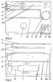
- the overhead projector consists of a housing 1, a support arm 2, which can be folded in many types, and a projection head 3, which has a lens 4 and a deflection mirror 5.
- the surface of the housing 1 forms a crystal-clear writing plate 6.
- Inside the housing is the light source with the metal vapor lamp 7, a Fresnel lens 8, an LCD 9 and two blowers 10, 11.
- the interior of the housing 1 is divided into at least two spaces 13, 14 by the partition 12 and the Fresnel lens 8.
- the space 13 is angular and has two legs 13A, 13B. It surrounds room 14 on two sides.
- the partition 12 and the Fresnel lens 8 form a thermal shield or separation between the two rooms.
- In the leg 13A of the angular space 13 there is an air inlet grille 15, behind and next to which the electronics 16 for the metal vapor lamp is arranged.
- the air entering through the air inlet grille 15 is sucked in by the cross-flow blower 10 and pressed into the leg 13B of the space 13, where the air passes on both sides of the LCD 9, on the underside of the clear writing plate 6 and on the top of the Fresnel lens 8, then sweeps past the electronics 17 for the LCD and leaves the room 13 through the air outlet grille 18.
- the electronics 16 for the metal halide lamp 7 are first cooled by the air entering the housing 1 from below, which is of great importance for safe operation of the metal halide lamp 7.
- the metal vapor lamp 7 with its base 20 is located in the room 14. As shown in FIGS. 2 and 3, it can be accommodated in a duct 19, in which air is sucked in through the air inlet grille 21 by means of the axial fan 11, which blows the duct 19 leaves through the air outlet grille 22.
- the air duct 19 is formed by a tube, which consists of two parts, a translucent part 23 and an opaque part 24.
- the translucent part 23 is directed towards the deflecting mirror 25, which is supported by the partition wall 12.
- the deflecting mirror 25 directs the light emerging from the metal vapor lamp 7 onto the Fresnel lens 8, so that the light can pass through this Fresnel lens 8 and then pass through the LCD 9 and the writing plate 6 to the projection head 3.
- Light-absorbing and / or reflecting dark-colored shielding plates or walls can be attached on both sides of the deflecting mirror 25, the angular position of which ensures that no radiation from the metal vapor lamp passes through the air inlet and outlet grilles to the outside.
- Appropriate shielding plates are also expediently provided in the vicinity of the lamp.
- the space is 14 divided into two parts by a translucent, heat radiation absorbing plate 26, both of which are crossed out by the air conveyed by the axial fan 11 from the air inlet grille 21 to the air outlet grille 22.
- the angular design of the room 13 has the advantage that the cross-flow fan 10 can be accommodated in a very advantageous manner.
- the room 13 is no longer angled, but is only arranged above the room 14.
- This space 13 is on both sides beyond the space 13, but the accommodation of the cross-flow fan 10 is not as easy as is the case with the other designs here: the cross-flow fan 10 is arranged here in front of the electronics 17 for the LCD, behind the air inlet grille 15 to have enough space for the electronics 16 of the metal halide lamp 7.
- This design results in a design in which the parts of the space 14 which project beyond the space 13 on both sides form projections 27 which are gripped by both hands when the projector is carried and thus make it easier to carry the projector.
- a heat filter located between the lamp and the deflecting mirror can serve well and reduce the effects of heat on the LCD.
- At least one joint is provided on and / or in the support arm, it is also advantageous to install a zoom lens.
- the liquid crystal display device is not built into the space 13, but is designed as a device 28 to be placed on the writing surface.
- the light source has a metal vapor lamp 7, if the metal vapor lamp 7 is operated with the aid of an electronic control device 16, if the housing 1 has two spaces 13, 14 ventilated by a blower 10, 11, which by a thermal insulation are separated from each other, of which one room 14 receives the metal halide lamp 7 and the other room the Fresnel lens 8, and the electronics 16 for the metal halide lamp 7 and the electronics 17 for the LCD 9.
- the LCD itself is housed in a separate frame, which is to be placed on the writing plate as a separate device 28.
- an operating hour counter and a shutdown device controlled by the operating hour counter are provided for the operation of the metal vapor lamp, which deactivates the projection device after 750 operating hours. if a pre-warning device comes into operation a certain time before decommissioning and indicates the end of the operating time by light or acoustic signals.
- an operating hours counter 30 and a shutdown device 29 controlled by the operating hours counter 30 are provided for the operation of the metal vapor lamp 7, which switches the projection device out of operation after a certain number of operating hours, preferably 750 operating hours, it being expedient if one a certain time before the decommissioning, a pre-warning device 31 comes into operation and indicates the end of the operating time by light or acoustic signals.
- An electrical line leads from the device switch 32 into the operating hours counter 30, to which the shutdown device 29 and the prewarning device 31 are connected on the one hand.
- the operating hours counter 30 activates the prewarning device 31 and, one hour later, the shutdown device 29. After changing the lamp, the operating hours counter 30 is reset to zero.
Landscapes
- Physics & Mathematics (AREA)
- General Physics & Mathematics (AREA)
- Projection Apparatus (AREA)
Priority Applications (1)
| Application Number | Priority Date | Filing Date | Title |
|---|---|---|---|
| EP94103934A EP0670512A1 (fr) | 1994-03-03 | 1994-03-14 | Rétroprojecteur pour la projection d'images affichés sur des cristaux liquides |
Applications Claiming Priority (3)
| Application Number | Priority Date | Filing Date | Title |
|---|---|---|---|
| EP94103155 | 1994-03-03 | ||
| EP94103155 | 1994-03-03 | ||
| EP94103934A EP0670512A1 (fr) | 1994-03-03 | 1994-03-14 | Rétroprojecteur pour la projection d'images affichés sur des cristaux liquides |
Publications (1)
| Publication Number | Publication Date |
|---|---|
| EP0670512A1 true EP0670512A1 (fr) | 1995-09-06 |
Family
ID=26135497
Family Applications (1)
| Application Number | Title | Priority Date | Filing Date |
|---|---|---|---|
| EP94103934A Withdrawn EP0670512A1 (fr) | 1994-03-03 | 1994-03-14 | Rétroprojecteur pour la projection d'images affichés sur des cristaux liquides |
Country Status (1)
| Country | Link |
|---|---|
| EP (1) | EP0670512A1 (fr) |
Cited By (3)
| Publication number | Priority date | Publication date | Assignee | Title |
|---|---|---|---|---|
| GB2306266A (en) * | 1995-10-13 | 1997-04-30 | Grunwald Projektoren Ag | LCD projector with uniform cooling of the LCD |
| GB2306267A (en) * | 1995-10-13 | 1997-04-30 | Grunwald Projektoren Ag | LCD projector with metal-vapour lamp |
| GB2364135A (en) * | 2000-06-27 | 2002-01-16 | Rever Comp Inc | Liquid crystal display or transparency overhead projector |
Citations (6)
| Publication number | Priority date | Publication date | Assignee | Title |
|---|---|---|---|---|
| DE3031857A1 (de) * | 1980-08-23 | 1982-03-11 | Fa. Ed. Liesegang, 4000 Düsseldorf | Projektor zum betrachten von einzelbildern eines mikroplanfilmes oder einer mikrofilm-lochkarte |
| US4763993A (en) * | 1987-04-30 | 1988-08-16 | N-View Corporation | Liquid crystal display for projection systems |
| US4904079A (en) * | 1986-08-13 | 1990-02-27 | Sharp Kabushiki Kaisha | Liquid crystal display device for overhead projector |
| US5134491A (en) * | 1990-01-18 | 1992-07-28 | Matsushita Electric Industrial Co., Ltd. | Projection type image display apparatus |
| WO1993020478A2 (fr) * | 1992-03-31 | 1993-10-14 | Minnesota Mining And Manufacturing Company | Retroprojecteur pour panneau afficheur a cristaux liquides |
| JPH0618986A (ja) * | 1992-07-02 | 1994-01-28 | Fuji Xerox Co Ltd | オーバーヘッドプロジェクタ |
-
1994
- 1994-03-14 EP EP94103934A patent/EP0670512A1/fr not_active Withdrawn
Patent Citations (6)
| Publication number | Priority date | Publication date | Assignee | Title |
|---|---|---|---|---|
| DE3031857A1 (de) * | 1980-08-23 | 1982-03-11 | Fa. Ed. Liesegang, 4000 Düsseldorf | Projektor zum betrachten von einzelbildern eines mikroplanfilmes oder einer mikrofilm-lochkarte |
| US4904079A (en) * | 1986-08-13 | 1990-02-27 | Sharp Kabushiki Kaisha | Liquid crystal display device for overhead projector |
| US4763993A (en) * | 1987-04-30 | 1988-08-16 | N-View Corporation | Liquid crystal display for projection systems |
| US5134491A (en) * | 1990-01-18 | 1992-07-28 | Matsushita Electric Industrial Co., Ltd. | Projection type image display apparatus |
| WO1993020478A2 (fr) * | 1992-03-31 | 1993-10-14 | Minnesota Mining And Manufacturing Company | Retroprojecteur pour panneau afficheur a cristaux liquides |
| JPH0618986A (ja) * | 1992-07-02 | 1994-01-28 | Fuji Xerox Co Ltd | オーバーヘッドプロジェクタ |
Non-Patent Citations (1)
| Title |
|---|
| PATENT ABSTRACTS OF JAPAN vol. 018, no. 223 (P - 1729) 21 April 1994 (1994-04-21) * |
Cited By (4)
| Publication number | Priority date | Publication date | Assignee | Title |
|---|---|---|---|---|
| GB2306266A (en) * | 1995-10-13 | 1997-04-30 | Grunwald Projektoren Ag | LCD projector with uniform cooling of the LCD |
| GB2306267A (en) * | 1995-10-13 | 1997-04-30 | Grunwald Projektoren Ag | LCD projector with metal-vapour lamp |
| GB2364135A (en) * | 2000-06-27 | 2002-01-16 | Rever Comp Inc | Liquid crystal display or transparency overhead projector |
| GB2364135B (en) * | 2000-06-27 | 2002-06-19 | Rever Comp Inc | Multifunction overhead projector |
Similar Documents
| Publication | Publication Date | Title |
|---|---|---|
| DE3710628C2 (fr) | ||
| DE69708869T2 (de) | Thermisches kontrollsystem für anzeigevorrichtung | |
| EP0670512A1 (fr) | Rétroprojecteur pour la projection d'images affichés sur des cristaux liquides | |
| WO1987007394A1 (fr) | Affichage a cristaux liquides passif projetable | |
| DE9404181U1 (de) | Overheadprojektor für die Projektion von mittels eines LCD dargestellten Bildern | |
| DE19725935A1 (de) | Kombinierte Klimatisier- und Dunsthaube | |
| DE3507808A1 (de) | Filteranordnung zur versorgung reiner raeume | |
| DE1422266B1 (de) | Belueftungseinrichtung an Bildwerfern mit Bildmagazin | |
| DE7318811U (de) | Deckenleuchte zur hochleistungsbeleuchtung | |
| DE3323875C2 (fr) | ||
| DE3828562C2 (fr) | ||
| DE2304072A1 (de) | Diaprojektor fuer ein rundmagazin | |
| DE8815708U1 (de) | Vorrichtung für die Projektion elektronisch erzeugter Bilder | |
| DE683131C (de) | Prodektionslampengehaeuse, insbesondere fuer Kinowiedergabegeraete | |
| DE2723228C2 (de) | Episkop | |
| DE19538141A1 (de) | LCD - Projektor | |
| DE2347562C3 (de) | Allseits geschlossenes Kastengehäuse für luftgekühlte elektrische Geräte | |
| CH695172A5 (de) | Transparentbildprojektor und Bildträger. | |
| DE1681570U (de) | Kleinbild-projektor. | |
| DE19538271A1 (de) | LCD - Projektor | |
| DE359185C (de) | Wiedergabekino, bei dem die Filmspulen mit wagerechter Achse nebeneinanderliegen | |
| DE8704726U1 (de) | Overhead-Projektor | |
| DE4230474A1 (de) | Diaprojektionsgerät | |
| DE4413555A1 (de) | Lüftungsanordnung für Projektoren | |
| DE202025107946U1 (de) | Handventilator |
Legal Events
| Date | Code | Title | Description |
|---|---|---|---|
| PUAI | Public reference made under article 153(3) epc to a published international application that has entered the european phase |
Free format text: ORIGINAL CODE: 0009012 |
|
| AK | Designated contracting states |
Kind code of ref document: A1 Designated state(s): DE FR GB |
|
| STAA | Information on the status of an ep patent application or granted ep patent |
Free format text: STATUS: THE APPLICATION IS DEEMED TO BE WITHDRAWN |
|
| 18D | Application deemed to be withdrawn |
Effective date: 19960307 |