EP0670585A2 - Disjoncteur de puissance - Google Patents
Disjoncteur de puissance Download PDFInfo
- Publication number
- EP0670585A2 EP0670585A2 EP95710005A EP95710005A EP0670585A2 EP 0670585 A2 EP0670585 A2 EP 0670585A2 EP 95710005 A EP95710005 A EP 95710005A EP 95710005 A EP95710005 A EP 95710005A EP 0670585 A2 EP0670585 A2 EP 0670585A2
- Authority
- EP
- European Patent Office
- Prior art keywords
- circuit breaker
- coil
- breaker according
- contact
- plunger
- Prior art date
- Legal status (The legal status is an assumption and is not a legal conclusion. Google has not performed a legal analysis and makes no representation as to the accuracy of the status listed.)
- Withdrawn
Links
Images


Classifications
-
- H—ELECTRICITY
- H01—ELECTRIC ELEMENTS
- H01H—ELECTRIC SWITCHES; RELAYS; SELECTORS; EMERGENCY PROTECTIVE DEVICES
- H01H71/00—Details of the protective switches or relays covered by groups H01H73/00 - H01H83/00
- H01H71/10—Operating or release mechanisms
- H01H71/1045—Multiple circuits-breaker, e.g. for the purpose of dividing current or potential drop
-
- H—ELECTRICITY
- H01—ELECTRIC ELEMENTS
- H01H—ELECTRIC SWITCHES; RELAYS; SELECTORS; EMERGENCY PROTECTIVE DEVICES
- H01H71/00—Details of the protective switches or relays covered by groups H01H73/00 - H01H83/00
- H01H71/10—Operating or release mechanisms
- H01H71/12—Automatic release mechanisms with or without manual release
- H01H71/40—Combined electrothermal and electromagnetic mechanisms
- H01H2071/407—Combined electrothermal and electromagnetic mechanisms the thermal element being heated by the coil of the electromagnetic mechanism
-
- H—ELECTRICITY
- H01—ELECTRIC ELEMENTS
- H01H—ELECTRIC SWITCHES; RELAYS; SELECTORS; EMERGENCY PROTECTIVE DEVICES
- H01H37/00—Thermally-actuated switches
- H01H37/02—Details
- H01H37/32—Thermally-sensitive members
- H01H37/52—Thermally-sensitive members actuated due to deflection of bimetallic element
- H01H37/54—Thermally-sensitive members actuated due to deflection of bimetallic element wherein the bimetallic element is inherently snap acting
-
- H—ELECTRICITY
- H01—ELECTRIC ELEMENTS
- H01H—ELECTRIC SWITCHES; RELAYS; SELECTORS; EMERGENCY PROTECTIVE DEVICES
- H01H71/00—Details of the protective switches or relays covered by groups H01H73/00 - H01H83/00
- H01H71/08—Terminals; Connections
Definitions
- the invention relates to a circuit breaker according to the preamble of claim 1.
- a circuit breaker with a magnetic tripping device which is designed up to about 50 A, is known from EP 144 799 B1. Such a circuit breaker should be miniaturized as much as possible despite increased performance.
- Miniature circuit breakers are provided according to the standard up to a rated current of 125 A. Since standard distances or standard pitches (e.g. 18 mm) are specified for the use of miniature circuit breakers and the switchgear with higher rated currents must also be used in the busbar system, the geometric dimensions and connection dimensions must also be congruent with the known miniature circuit breakers with smaller rated currents, even with miniature circuit breakers with higher rated currents be carried out. For economic reasons, it would be incorrect for miniature circuit breakers with high rated currents, to develop their own implementations, since the range of applications of such miniature circuit breakers is naturally smaller than with miniature circuit breakers with lower rated currents, especially since new tools and other production facilities would be required.
- standard distances or standard pitches e.g. 18 mm
- the invention has for its object to provide a circuit breaker for higher rated currents, the simple structure, as far as possible is miniaturized and can be manufactured while avoiding special designs.
- the invention provides a circuit breaker which, according to a preferred embodiment, has a magnetic release device which consists of two magnetic releases connected in parallel, i.e. the coils of the magnetic releases are connected in parallel with one another.
- the parallel connection of the coils of the magnetic release device in contrast to two mutually parallel circuit breakers, which are each designed up to 50 A and which would theoretically result in a 100 amp device, ensures a symmetrical current distribution.
- the simple parallel connection of two line circuit breakers does not provide a symmetrical current distribution between the two line circuit breakers connected in parallel, the parallel connection of which would take place with regard to the connection terminals.
- the two coils of the magnetic release device are connected in parallel in that an internal connection is provided.
- This additional internal connection or compensating line ensures that the current through the two coils is distributed evenly and that there is no different current flow through the two branches of the parallel connection due to different contact resistances at the contacts, at welding and connection points, etc.
- clamp clamps are preferably provided as connection terminals, which allow the connection of multi-wire conductors up to 50 mm2 by means of two screws in each case. If the standard pitch of, for example, 18 mm is maintained for the distance between the two clamping screws, it is easily possible to use such a circuit breaker for high rated currents for standard busbars together with switching devices with lower rated currents in a network.
- the coil is preferably used both as a magnetic release and as a heater for the thermal release, as a result of which the bimetal itself is not flowed through by current.
- the miniature circuit breaker according to the invention is used for a rated current of> 63 A, for example 100 A and, according to a preferred embodiment, consists of two 50 A miniature circuit breakers, is accordingly subjected to two 50 A, so that the 100 A miniature circuit breaker according to the invention has the same behavior shows like a 50 A circuit breaker.
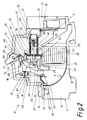
- a preferred embodiment of a circuit breaker 10 which has a narrowly constructed housing 11 made of an insulating plastic and on its rear side, in Fig. 1 and 2 below, suspension mounts 12 and 13 for a conventional mounting rail.
- the housing 11 has an interior 14 and an upper section 15 with a connecting terminal 16 and a lower section 17 with a connecting terminal 18th
- the connecting terminal 16 is connected to the movable contact 25 of the contact device 21 via a movable strand 24.
- the complementary fixed contact 26 of the contact device 21 is formed as a section of an approximately 1.2 mm thick solid conductor 27 which extends from the overcurrent release 22 via the fixed contact 26 and a horn section 28 to the high-performance arc extinguishing package 23.
- An arc-shaped arc guide plate 30 extends between an angled section 29 of the connecting terminal 16, to which the strand 24 is also fastened, and a rear region near the quenching package 23.
- connection terminal 18 is connected to the overcurrent release 22 via a welding contact point 31.
- the overcurrent release 22 has a heat-conducting, rotationally symmetrical hollow cylindrical support body 32 with a section which a coil 33 is wound in close contact.
- One end of the coil 33 is connected to the connecting terminal 18 via the soldering point 31.
- the other end of the coil 33 is guided to a soldering point 34 which is connected to the conductor 27 via a holding plate 35 in the front region of the support body 32.
- the holding plate 35 is used to fasten the support body 32 in the interior 14 of the housing 11 by means of an axis 36, which simultaneously functions as an axis of rotation for a two-armed lever 37.
- the two-armed lever 37 has a first arm 38 with a unlatching nose 39, a molded-in position section 40, which is overlapped by the holding plate 35, and a second arm 41, which is designed to strike a plunger 42 of the overcurrent release 22 within the position section 40.
- the second arm 41 has a molded-on baffle 43 on its rear side (in FIGS. 1 and 2 on its underside) and a lug 44 through which the movable contact 25 can be opened, which is located on a first arm 45 of a two-armed contact lever 46 is located.
- a movable plunger loading anchor 47 is arranged, which is biased by a spring 48, which is guided by the plunger 42, against a plunger guide core 49.
- the tappet guide core 49 has a central bore 50 in which the tappet 42 is guided.
- the tappet guide core 49 like the tappet actuating anchor 47, is constructed to be rotationally symmetrical.
- the plunger guide core 49 is fastened in the hollow cylindrical interior of the support body 32.
- a bimetallic chamber 51 is formed in front of the tappet guide core 49, ie to the left of this in FIGS. 1 and 2, in which a bimetallic snap disk 52 is held in an enlarged section of the supporting body 32 by means of a disk-shaped element 53.
- the bimetallic disc 52 has a central bore, which only slightly exceeds the diameter of the plunger 42, in order to be able to act on a disc engagement molding 54 of the plunger 42 for a thermally induced release or disengagement of the plunger 42.
- the disc element 53 also has a passage opening 55 for the plunger 42, which protrudes up to its stop on the two-armed lever 37 in its molded-in position section 40.
- the conductor 27 is fastened in a receptacle 56 of the disk-shaped element 53 and is conductively connected to the other end of the coil, the conductor 27 having a straight arc guide rail section 57 after the horn section 28, which extends parallel to the front side of the quenching package 23.
- the unlatching lug 39 of the two-armed lever 37 is provided for engagement on an angled release lever 58, which forms a functional component of the switching lock 19.
- the trigger lever 58 is mounted on an axle 59 fixed to the housing, which also forms the axis of rotation for the switching knob 20.
- the switching lock 19 also includes the two-armed contact lever 46 with an elongated hole 61, which extends approximately transversely to the contact lever 46 and through which a housing-fixed axis 63 engages to guide the contact lever 46.
- the contact lever 46 is biased in a clockwise direction on the housing 11 via a spring 67 and is connected in an articulated manner to an intermediate lever 69.
- the nose-shaped free end 73 of the intermediate lever 69 engages in a latching manner with a stop 70 of the release lever 58 and has an elongated hole 74.
- a bracket 75 engages with one end in the elongated hole 74 and with its other end in a bore 76 which is formed in a projection 77 of the switching knob 20 is formed.
- the plunger 42 is disengaged from the position shown in FIG. 1 either electromagnetically or by means of the bimetallic disk 52 due to its snapping and strikes the second Arm 41 of the two-armed lever 37. This causes the movable contact 25 of the contact device 21 to be opened by means of the nose 44, which strikes the first arm 45 of the contact lever 46.
- the material of the two-armed lever 37 which consists of an insulating material which emits gas under the action of an arc, gas is released intermittently, in particular from plexiglass. This advantageously presses the resulting arc to the quenching package 23, the baffle 43 of the lever 37 guiding the arc in the intended direction when it strikes.
- the unlatching lug 39 of the two-armed lever 37 engages the release lever 58, as a result of which the latch is released with the intermediate lever 69 and the contact lever 45 is rotated clockwise under the pressure of the spring 67.
- the bracket 75 is moved to the right via the intermediate lever 69 with the result that the switching knob 20 rotates counterclockwise into the switched-off position and the movable contact lever 46 is held in the open position.
- the switching mechanism 19 thus reliably keeps the contact device 21 open.
- circuit breaker for a rated current of, for example, 100 A, a double design of the individual parts described in connection with FIGS. 1 and 2 is provided, that is to say all the parts described above are provided twice and thus also two overcurrent releases 22 in the still to be described Are connected in parallel.
- the connection terminals 16 of the two units are additionally connected in parallel, as will be described below.
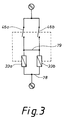
- the two coils 33 are connected to one another on the input side and also on the output side in order to ensure a symmetrical current distribution.
- the two coils are designated 33a, 33b, which are each assigned to the tripping mechanism or overcurrent release 22 described in connection with Figs. 1 and 2.
- the contact or contact lever assigned to each coil 33a, 33b is designated 46a or 46b in FIG. 3. 3
- the contact lever 46a is thus opened by the plunger 42 moved by means of the coil 33a and the contact lever 46b by the plunger 42 activated by the coil 33b. This means that the contact levers 46a, 46b are not coupled to one another via a mechanism or must be coupled. If an overcurrent flows through the coil 33a, the contact lever 46a is opened. If an overcurrent continues to flow, then the contact lever 46b is opened immediately within a very short time due to the current flow then occurring exclusively via the coil 33b.
- the two coils 33a, 33b are electrically coupled to one another on the output side by a connection 79, and the two coils are likewise coupled directly to one another by a corresponding electrical connection on the input side.
- FIG. 4 shows a view of the line circuit breaker according to the invention, in which the two toggles designated 20a, 20b in FIG. 4 are coupled to one another by a handle connection 80.
- a handle connection 80 In this way, both a manual closing of both contact levers 46a, 46b after tripping by an overcurrent is ensured, as well as the simultaneous opening of these contact levers in a manual manner.
- the connection of the input-side as well as the output-side conductors is carried out with the help of trestle clamps, which are shown schematically in FIG. 5 and are therefore provided on the input side as well as the output side of the line circuit breaker.
- 5 is preferably located on the side of the circuit breaker shown on the left and right in FIG. 4, with the clamp clamp representing the connection to the connection terminals designated 16 and 18 in FIGS. 1 and 2, respectively.
- the coil 33a, 33b is used both as a magnetic release and as a heater for the thermal release, as a result of which the bimetal used in the form of the bimetallic snap disk 52 does not have a current flowing through it.
- the circuit breaker according to the invention uses two identical units, with the proviso that the two coils of the two units are connected to one another on the input side and on the output side.
- a double-T housing for accommodating the line circuit breaker according to the invention and the larger connecting terminal in the form of the trestle clamp terminals according to FIG. 5, no further new parts are required for known rated circuit breakers for small rated currents.
Landscapes
- Physics & Mathematics (AREA)
- Electromagnetism (AREA)
- Breakers (AREA)
Applications Claiming Priority (2)
| Application Number | Priority Date | Filing Date | Title |
|---|---|---|---|
| DE4406670A DE4406670C3 (de) | 1994-03-01 | 1994-03-01 | Leitungsschutzschalter |
| DE4406670 | 1994-03-01 |
Publications (2)
| Publication Number | Publication Date |
|---|---|
| EP0670585A2 true EP0670585A2 (fr) | 1995-09-06 |
| EP0670585A3 EP0670585A3 (fr) | 1997-10-29 |
Family
ID=6511523
Family Applications (1)
| Application Number | Title | Priority Date | Filing Date |
|---|---|---|---|
| EP95710005A Withdrawn EP0670585A3 (fr) | 1994-03-01 | 1995-02-09 | Disjoncteur de puissance. |
Country Status (4)
| Country | Link |
|---|---|
| US (1) | US5565828A (fr) |
| EP (1) | EP0670585A3 (fr) |
| AU (1) | AU682429B2 (fr) |
| DE (1) | DE4406670C3 (fr) |
Cited By (1)
| Publication number | Priority date | Publication date | Assignee | Title |
|---|---|---|---|---|
| EP0702387A1 (fr) * | 1994-09-16 | 1996-03-20 | Eaton Corporation | Disjoncteur multipolaire avec température de fonctionneur réduite |
Families Citing this family (12)
| Publication number | Priority date | Publication date | Assignee | Title |
|---|---|---|---|---|
| DE19847155A1 (de) * | 1998-10-13 | 2000-04-20 | Kopp Heinrich Ag | Überstromauslöser |
| US6034586A (en) * | 1998-10-21 | 2000-03-07 | Airpax Corporation, Llc | Parallel contact circuit breaker |
| DE10120189A1 (de) * | 2001-04-24 | 2002-11-14 | Prodex Technologie Gmbh | Schutzeinrichtung mit elektromagnetischer Auslösung |
| US6563406B2 (en) * | 2001-06-15 | 2003-05-13 | Eaton Corporation | Multi-pole circuit breaker with parallel current |
| DE102004055564B4 (de) * | 2004-11-18 | 2022-05-05 | Abb Ag | Elektrisches Installationsschaltgerät |
| US7348514B2 (en) * | 2006-04-12 | 2008-03-25 | Eaton Corporation | Slot motor and circuit breaker including the same |
| DE102007001471A1 (de) * | 2007-01-05 | 2008-07-10 | Siemens Ag | Elektrische Schalteinrichtung |
| EP2544207B1 (fr) * | 2011-07-05 | 2017-03-29 | Siemens Aktiengesellschaft | Coupe-circuit avec connexion optimisée de la bobine |
| US10063815B1 (en) * | 2011-09-26 | 2018-08-28 | Jenesia1, Inc. | Mobile communication platform |
| DE202012013004U1 (de) * | 2012-12-15 | 2014-08-04 | Ellenberger & Poensgen Gmbh | Schutzschalter und Adapter für einen Schutzschalter |
| US9653224B2 (en) * | 2015-10-13 | 2017-05-16 | Eaton Corporation | Interruption apparatus employing actuator having movable engagement element |
| SI25460B (sl) * | 2017-06-06 | 2021-11-30 | Nela Razvojni Center Za Elektroindustrijo In Elektroniko, D.O.O. | Izpopolnjen termično-magnetni prožilnik varnostnega električnega stikala |
Family Cites Families (15)
| Publication number | Priority date | Publication date | Assignee | Title |
|---|---|---|---|---|
| DE508066C (de) * | 1930-09-24 | Siemens Schuckertwerke Akt Ges | Einrichtung zum Schalten grosser Schaltleistungen durch parallel liegende Selbstschalter | |
| US3278708A (en) * | 1965-11-26 | 1966-10-11 | Gen Electric | Electric circuit breaker with thermal magnetic trip |
| US3412349A (en) * | 1966-11-25 | 1968-11-19 | Gen Electric | Current-limiting electric circuit breaker |
| US3786380A (en) * | 1973-02-16 | 1974-01-15 | Airpax Electronics | Multi-pole circuit breaker |
| DE2402092A1 (de) * | 1974-01-17 | 1975-07-31 | Licentia Gmbh | Einpoliger leitungsschutzschalter hoeherer nennstromstaerke |
| FR2414784A1 (fr) * | 1978-01-11 | 1979-08-10 | Merlin Gerin | Dispositif de liaison de manettes de commande de disjoncteurs |
| DE2905257A1 (de) * | 1979-02-12 | 1980-08-21 | Wella Ag | Haarbehandlungsmittel |
| US4492941A (en) * | 1983-02-18 | 1985-01-08 | Heinemann Electric Company | Circuit breaker comprising parallel connected sections |
| DE3342469A1 (de) * | 1983-11-24 | 1985-06-05 | Bbc Brown Boveri & Cie | Elektrischer schalter |
| DE3515158A1 (de) * | 1985-04-26 | 1986-11-06 | Lindner Gmbh, Fabrik Elektrischer Lampen Und Apparate, 8600 Bamberg | Hochampere-ueberstromschutzschalter |
| DE3637275C1 (en) * | 1986-11-03 | 1988-05-05 | Flohr Peter | Overcurrent trip device for protection switching apparatuses |
| FR2624650B1 (fr) * | 1987-12-10 | 1990-04-06 | Merlin Gerin | Disjoncteur multipolaire a boitier moule de calibre eleve |
| DE3908350A1 (de) * | 1989-03-15 | 1990-09-20 | Asea Brown Boveri | Elektrische spule |
| DE3915127C1 (fr) * | 1989-05-09 | 1990-09-06 | Flohr, Peter, Dipl.-Ing., 7790 Messkirch, De | |
| US5162765A (en) * | 1991-12-23 | 1992-11-10 | North American Philips Corporation | Adjustable magnetic tripping device and circuit breaker including such device |
-
1994
- 1994-03-01 DE DE4406670A patent/DE4406670C3/de not_active Expired - Fee Related
-
1995
- 1995-02-09 EP EP95710005A patent/EP0670585A3/fr not_active Withdrawn
- 1995-02-27 US US08/395,010 patent/US5565828A/en not_active Expired - Fee Related
- 1995-02-28 AU AU13568/95A patent/AU682429B2/en not_active Ceased
Cited By (1)
| Publication number | Priority date | Publication date | Assignee | Title |
|---|---|---|---|---|
| EP0702387A1 (fr) * | 1994-09-16 | 1996-03-20 | Eaton Corporation | Disjoncteur multipolaire avec température de fonctionneur réduite |
Also Published As
| Publication number | Publication date |
|---|---|
| EP0670585A3 (fr) | 1997-10-29 |
| AU1356895A (en) | 1995-09-07 |
| US5565828A (en) | 1996-10-15 |
| AU682429B2 (en) | 1997-10-02 |
| DE4406670C3 (de) | 1999-09-09 |
| DE4406670C2 (de) | 1997-03-06 |
| DE4406670A1 (de) | 1995-09-14 |
Similar Documents
| Publication | Publication Date | Title |
|---|---|---|
| EP1203385B1 (fr) | Ensemble coupe-circuit multipolaire pour jeux de barres collectrices | |
| EP0563774A2 (fr) | Disjoncteur de protection avec commande à distance | |
| DE4406670C2 (de) | Leitungsschutzschalter | |
| DE670790C (de) | Thermisch wirkender Selbstschalter | |
| EP0563775B1 (fr) | Disjoncteur de protection commandé par bimétal | |
| EP0222181B1 (fr) | Disjoncteur de surintensité | |
| EP0287752B1 (fr) | Interrupteur électromagnétique avec entraînement électromagnétique | |
| WO2009114890A1 (fr) | Module de déclenchement pour un appareil de commutation | |
| EP1470565B1 (fr) | Appareil de distribution electrique | |
| EP0621619B1 (fr) | Disjoncteur de ligne | |
| DE3727356A1 (de) | Elektrisches schaltgeraet | |
| EP0391086A1 (fr) | Dispositeur de protection à courant excessif commandé par un bouton-poussoir | |
| EP0195816B1 (fr) | Declencheur bimetallique | |
| DE2363916B2 (de) | Mehrpoliger Selbstschalter mit Auslöseantrieb und statischem Auswertungsgerät | |
| DE3602123C2 (de) | Sicherungsautomat | |
| DE2118175A1 (de) | Leistungsschalter mit eingebauten Schmelzsicherungen | |
| DE3882601T2 (de) | Magnetothermische ausloeseeinheit fuer lastschalter oder differentiallastschalter. | |
| EP1243013B1 (fr) | Commutateur de simulation | |
| EP0310943B1 (fr) | Appareil de commutation électrique | |
| DE69507566T2 (de) | Selbstschalter mit einem Thermoschutzbauteil | |
| DE29502573U1 (de) | Schaltgerät, insbesondere Leitungsschutzschalter | |
| DE3808012C2 (fr) | ||
| DE19903751A1 (de) | Elektromechanisches Schaltgerät | |
| EP1096529B1 (fr) | Disjoncteur de protection électrique | |
| EP0599800B1 (fr) | Disjoncteur de ligne |
Legal Events
| Date | Code | Title | Description |
|---|---|---|---|
| PUAI | Public reference made under article 153(3) epc to a published international application that has entered the european phase |
Free format text: ORIGINAL CODE: 0009012 |
|
| AK | Designated contracting states |
Kind code of ref document: A2 Designated state(s): CH DE GB LI |
|
| PUAL | Search report despatched |
Free format text: ORIGINAL CODE: 0009013 |
|
| AK | Designated contracting states |
Kind code of ref document: A3 Designated state(s): CH DE GB LI |
|
| 17P | Request for examination filed |
Effective date: 19971028 |
|
| 17Q | First examination report despatched |
Effective date: 19980114 |
|
| STAA | Information on the status of an ep patent application or granted ep patent |
Free format text: STATUS: THE APPLICATION IS DEEMED TO BE WITHDRAWN |
|
| 18D | Application deemed to be withdrawn |
Effective date: 19980526 |