EP0670613A1 - Elektrisches Gerät, dessen Vorrichtung in einem wasserdichten Gehäuse montierbar ist, Versehen mit einer Abdeckung und einem Deckel - Google Patents
Elektrisches Gerät, dessen Vorrichtung in einem wasserdichten Gehäuse montierbar ist, Versehen mit einer Abdeckung und einem Deckel Download PDFInfo
- Publication number
- EP0670613A1 EP0670613A1 EP95400440A EP95400440A EP0670613A1 EP 0670613 A1 EP0670613 A1 EP 0670613A1 EP 95400440 A EP95400440 A EP 95400440A EP 95400440 A EP95400440 A EP 95400440A EP 0670613 A1 EP0670613 A1 EP 0670613A1
- Authority
- EP
- European Patent Office
- Prior art keywords
- cover
- seal
- flap
- passage
- electrical device
- Prior art date
- Legal status (The legal status is an assumption and is not a legal conclusion. Google has not performed a legal analysis and makes no representation as to the accuracy of the status listed.)
- Granted
Links
- 238000000465 moulding Methods 0.000 claims description 7
- 239000000463 material Substances 0.000 claims description 5
- 238000004873 anchoring Methods 0.000 claims description 3
- 238000005553 drilling Methods 0.000 claims description 3
- 238000002513 implantation Methods 0.000 claims description 2
- 230000008901 benefit Effects 0.000 description 3
- 238000002347 injection Methods 0.000 description 3
- 239000007924 injection Substances 0.000 description 3
- 238000005520 cutting process Methods 0.000 description 2
- 238000007789 sealing Methods 0.000 description 2
- 239000000853 adhesive Substances 0.000 description 1
- 238000004026 adhesive bonding Methods 0.000 description 1
- 230000001070 adhesive effect Effects 0.000 description 1
- 239000004020 conductor Substances 0.000 description 1
- 238000009434 installation Methods 0.000 description 1
- 238000004519 manufacturing process Methods 0.000 description 1
- 238000000034 method Methods 0.000 description 1
Images

Classifications
-
- H—ELECTRICITY
- H01—ELECTRIC ELEMENTS
- H01R—ELECTRICALLY-CONDUCTIVE CONNECTIONS; STRUCTURAL ASSOCIATIONS OF A PLURALITY OF MUTUALLY-INSULATED ELECTRICAL CONNECTING ELEMENTS; COUPLING DEVICES; CURRENT COLLECTORS
- H01R13/00—Details of coupling devices of the kinds covered by groups H01R12/70 or H01R24/00 - H01R33/00
- H01R13/46—Bases; Cases
- H01R13/52—Dustproof, splashproof, drip-proof, waterproof, or flameproof cases
- H01R13/5213—Covers
-
- H—ELECTRICITY
- H01—ELECTRIC ELEMENTS
- H01R—ELECTRICALLY-CONDUCTIVE CONNECTIONS; STRUCTURAL ASSOCIATIONS OF A PLURALITY OF MUTUALLY-INSULATED ELECTRICAL CONNECTING ELEMENTS; COUPLING DEVICES; CURRENT COLLECTORS
- H01R2103/00—Two poles
-
- H—ELECTRICITY
- H01—ELECTRIC ELEMENTS
- H01R—ELECTRICALLY-CONDUCTIVE CONNECTIONS; STRUCTURAL ASSOCIATIONS OF A PLURALITY OF MUTUALLY-INSULATED ELECTRICAL CONNECTING ELEMENTS; COUPLING DEVICES; CURRENT COLLECTORS
- H01R24/00—Two-part coupling devices, or either of their cooperating parts, characterised by their overall structure
- H01R24/76—Two-part coupling devices, or either of their cooperating parts, characterised by their overall structure with sockets, clips or analogous contacts and secured to apparatus or structure, e.g. to a wall
Definitions
- the present invention relates generally to electrical devices whose mechanism is housed in a sealed housing because they are normally intended to be implemented in a humid atmosphere.
- casing comprises, overall, a casing body, which contains their mechanism and in which the wiring thereof is done, a cover, which closes the casing body while leaving access to the mechanism, a first seal, said below for convenience, cover seal, which is inserted between the cover and the housing body, a flap, which is articulated to the cover, to cover the part at least of the latter concerned by the mechanism, and a second seal, said below for simple convenience, flap seal, which intervenes between the flap and the cover when the flap is folded over the cover.
- the flap advantageously protects this socket, and therefore the underlying mechanism, when no socket plug is plugged in.
- the shutter seal is in itself a separate part, which, for its realization, requires a specific operation, and which must then be attached to the assembly.
- the flap seal is attached by gluing to the flap , for cooperation with the edge of the cover flange.
- this flap joint requires a non-negligible time prejudicial to the cost price of the assembly, its assembly with the flap is in practice frequently poorly controlled, in particular because the deposit of prior adhesive is always done more or less random.
- the present invention generally relates to a provision which makes it possible to avoid these drawbacks and which also leads to other advantages.
- any electrical appliance of the kind comprising, for housing any mechanism, a housing body, a cover which closes the housing body while leaving access to the mechanism, a first gasket sealing, here called cover seal, which is inserted between the cover and the housing body, a flap, which is articulated to the cover, to cover at rest the at least part thereof concerned by the mechanism, and a second seal sealing, here called flap gasket, which intervenes between the flap and the cover when the flap is folded over the cover
- this electrical device being generally characterized in that, jointly, on the one hand, the gasket flap extends to the upper surface of the cover and the cover seal is carried by the latter, and, on the other hand, the flap seal is integral with the cover seal, forming by molding one and the same part therewith, the cover being traversed right through by at least one passage through which the flap seal is in continuity with the cover seal.
- the cover on the one hand, and the flap and cover seals that it carries, on the other hand, result jointly from a two-material molding.
- the flap gasket advantageously does not require any particular operation, either for its production or for its assembly.
- this shutter seal being in a way trapped in the cover in the manner of an insert, its assembly with this cover is perfectly controlled, for the benefit of its behavior and the desired tightness.
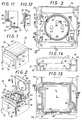
- an electrical device 10 has its mechanism 11 housed in a sealed housing 12.
- the housing 12 is generally parallelepipedic, with, in plan, a generally square contour.
- this housing 12 comprises a housing body 15, which allows the housing of the mechanism 11 and the connection to the latter of the electrical conductors, not shown, necessary for its service, a cover 16, which closes the body housing 15 while leaving access to the mechanism 11, a first seal 17, said here for convenience, cover seal, which, according to arrangements described in more detail later, is inserted between the cover 16 and the housing body 15, a flap 18, which is articulated to the cover 16, to cover, at rest, at least the part of it concerned by the mechanism 11, and a second seal 19, said here by simple convenience flap seal , which, according to methods also described in more detail later, intervenes between the flap 18 and the cover 16 when, as shown in FIG. 1, the flap 18 is folded over the cover 16.
- the cover 16 closes the housing body 15 at full section, and, on the contrary, the flap 18 only corresponds to a portion of the corresponding section, the cover 16 forming, in front of this flap 18, a step 20 facilitating the gripping thereof when it is in the folded position.
- the cover 16 has, laterally, projecting from its upper surface, two flanges 22, which extend perpendicular to the step 20, starting from the latter, and which, at their end opposite to this step 20, each respectively forms two openings 23 for which the flap 18 is articulated.
- this flange 24 has, in plan, a circular outline.
- the cover 16 further comprises, at its periphery, a dropped edge 30, which extends over its entire perimeter, and with which the preceding flanges 22 are each respectively locally in continuity.
- the cover 16 comprises, finally, at least one bore 31, which passes right through it, for the passage of any closure member, such as screw 32, Figure 2, or the like.
- two holes 31 are provided, in positions diagonally opposite one with respect to the other on either side of the well 25.
- the flap seal 19 extends to the upper surface of the cover 16 and the cover seal 17 is carried by the latter, and, on the other hand, the seal flap 19 is in one piece with the cover gasket 17, forming by molding a single and same part with the latter, the cover 16 being traversed right through by at least one passage 34, FIG. 6, through which the flap seal 19 is in continuity with the cover seal 17.
- the cover gasket 17, which extends annularly around the axis of the assembly, and which, in cross section, can have any profile, is embedded in the cover 16 in favor a recess 35 cutting the edge 36 of its fallen edge 30 and its inner surface.
- this cover gasket 17, which will not be described in more detail here, is in one piece with a skirt 38 which internally lines the fallen edge 30 of the cover 16 over the entire height. from this fallen edge 30.
- the flap seal 19 extends annularly around the flange 24 of the cover 16, away from the holes 31 of the latter, leaving these holes 31 outside its outer contour.
- the flap seal 19 extends in contact with the flange 24, by encircling the latter from its base, that is to say from the upper surface of the cover 16.
- the flap gasket 19 extends over almost the entire height of the flange 24, by being fitted thereon by means of a recess 39 cutting into its edge and its outer surface.
- the flap seal 19 is in continuity with the cover seal 17 by at least one bridge 40 which, in one piece with this flap seal 19, thanks to the corresponding passage 34 of the cover 16, s' extends to the lower surface of the cover 16 from this passage 34.
- a single passage 34 is provided, and, for this, a single bridge 40.
- this bridge 40 extends radially with respect to the well 25, between the passage 34 and the skirt 38, and it is integral with it.
- the cover 16 Independently of the passage 34 which connects the shutter seal 19 to the cover seal 17, and at a distance from this passage 34, the cover 16 is, in the embodiment shown, traversed right through by at least one other passage 34 ' by which the flap gasket 19 is in continuity with an anchoring stud 42 which, of larger dimensions, in plan, than those of this passage 34 ', extends to the lower surface of the cover 16, to strengthen the holding of this flap seal 19 thereon.
- a single passage 34 ' is provided in this embodiment, and, therefore, a single anchoring stud 42, flush with the well 25, and in a position diagonally opposite to that of the passage 34 relative to the latter. .
- each of the holes 31 of the cover 16 is individually surrounded by a specific seal 44, said below for simple convenience, seal, which, if desired, and as shown diagrammatically in FIG. 9 , can also be in continuity with the cover gasket 17, being connected in one piece by a bridge 45 thereto.
- the cover 16 has, on its upper surface, in the embodiment shown, at least one braking block 50 which is intended to cooperate in friction with a fallen edge 51 of the flap 18, for retaining the latter in the folded-down position, and which, by a passage 34 "passing right through the cover 16, is in continuity with the cover gasket 17, by the intermediate of the skirt 38.
- two brake blocks 50 are thus provided, at the ends, each respectively, of the flanges 22 of the cover 16, on the side of the step 20 thereof, and each of them is protected by a hook-shaped lug 53 which, coming in one piece from the upper surface of the cover 16, leaves it released laterally for cooperation with the fallen edge 51 correspondent for section 18.
- drilling joints 44 can also result from this two-material molding.
- the flap 18, meanwhile, has, projecting from its lower surface, for cooperation with the flap gasket 19 carried by the cover 16, a flange 55 whose outline, in plan, is the image of that of this flap seal 19.
- this collar 55 therefore has a circular outline in plan.
- the flap seal 19 has, at the outer periphery of its edge, in the embodiment shown, a step 56.
- FIGS. 13 and 14 illustrate, by way of example, the application of the invention to an electrical appliance 10 other than a socket outlet.
- It can for example be a switch, a back-and-forth or a push-button.
- the cover 16 comprises, in this case, instead of the well 25, a central recess 25 ′, for the implantation of the corresponding mechanism 11.
- the flap seal 19 extends annularly around this central recess 25 ', and, according to arrangements of the type described above, it is continuous with the corresponding cover seal, not visible on the figures.
- this flap seal 19 bypasses by its internal contour the holes 31 that the cover 16 comprises.
Landscapes
- Connector Housings Or Holding Contact Members (AREA)
- Brushes (AREA)
- Casings For Electric Apparatus (AREA)
- Details Of Aerials (AREA)
- Electric Clocks (AREA)
- Input Circuits Of Receivers And Coupling Of Receivers And Audio Equipment (AREA)
- Transmitters (AREA)
- Telephone Function (AREA)
- Closures For Containers (AREA)
- Cookers (AREA)
- Massaging Devices (AREA)
Applications Claiming Priority (2)
| Application Number | Priority Date | Filing Date | Title |
|---|---|---|---|
| FR9402398A FR2717034B1 (fr) | 1994-03-02 | 1994-03-02 | Appareil électrique dont le mécanisme est logé dans un boîtier étanche comportant un couvercle et un volet. |
| FR9402398 | 1994-03-02 |
Publications (2)
| Publication Number | Publication Date |
|---|---|
| EP0670613A1 true EP0670613A1 (de) | 1995-09-06 |
| EP0670613B1 EP0670613B1 (de) | 1996-12-27 |
Family
ID=9460591
Family Applications (1)
| Application Number | Title | Priority Date | Filing Date |
|---|---|---|---|
| EP95400440A Expired - Lifetime EP0670613B1 (de) | 1994-03-02 | 1995-03-01 | Elektrisches Gerät, dessen Vorrichtung in einem wasserdichten Gehäuse montierbar ist, Versehen mit einer Abdeckung und einem Deckel |
Country Status (7)
| Country | Link |
|---|---|
| EP (1) | EP0670613B1 (de) |
| AT (1) | ATE146909T1 (de) |
| DE (1) | DE69500117T2 (de) |
| ES (1) | ES2096501T3 (de) |
| FR (1) | FR2717034B1 (de) |
| GR (1) | GR3022711T3 (de) |
| MA (1) | MA23443A1 (de) |
Cited By (3)
| Publication number | Priority date | Publication date | Assignee | Title |
|---|---|---|---|---|
| EP1163987A1 (de) * | 2000-06-13 | 2001-12-19 | Izumi Products Company | Dichtungsstruktur |
| ES2281293A1 (es) * | 2006-03-08 | 2007-09-16 | Simon, S.A. | Caja estanca de superficie o empotrable para mecanismos electricos. |
| EP1806813A3 (de) * | 2006-01-06 | 2008-06-18 | Delphi Technologies, Inc. | Elektrischer Verbindungskörper mit angeformtem Kabel und Außenabdichtungen |
Citations (2)
| Publication number | Priority date | Publication date | Assignee | Title |
|---|---|---|---|---|
| DE903357C (de) * | 1943-12-30 | 1954-02-04 | Robert Berker | Gehaeuse fuer wasserdicht gekapselte Installationsschalter oder Steckdosen |
| US3252611A (en) * | 1964-06-17 | 1966-05-24 | Slater Electric Inc | Weatherproof electrical outlet box cover |
-
1994
- 1994-03-02 FR FR9402398A patent/FR2717034B1/fr not_active Expired - Fee Related
-
1995
- 1995-02-03 MA MA23770A patent/MA23443A1/fr unknown
- 1995-03-01 AT AT95400440T patent/ATE146909T1/de not_active IP Right Cessation
- 1995-03-01 ES ES95400440T patent/ES2096501T3/es not_active Expired - Lifetime
- 1995-03-01 EP EP95400440A patent/EP0670613B1/de not_active Expired - Lifetime
- 1995-03-01 DE DE69500117T patent/DE69500117T2/de not_active Expired - Fee Related
-
1997
- 1997-03-03 GR GR960403595T patent/GR3022711T3/el unknown
Patent Citations (2)
| Publication number | Priority date | Publication date | Assignee | Title |
|---|---|---|---|---|
| DE903357C (de) * | 1943-12-30 | 1954-02-04 | Robert Berker | Gehaeuse fuer wasserdicht gekapselte Installationsschalter oder Steckdosen |
| US3252611A (en) * | 1964-06-17 | 1966-05-24 | Slater Electric Inc | Weatherproof electrical outlet box cover |
Cited By (5)
| Publication number | Priority date | Publication date | Assignee | Title |
|---|---|---|---|---|
| EP1163987A1 (de) * | 2000-06-13 | 2001-12-19 | Izumi Products Company | Dichtungsstruktur |
| US6543788B2 (en) | 2000-06-13 | 2003-04-08 | Izumi Products Company | Seal structure |
| EP1806813A3 (de) * | 2006-01-06 | 2008-06-18 | Delphi Technologies, Inc. | Elektrischer Verbindungskörper mit angeformtem Kabel und Außenabdichtungen |
| US7749012B2 (en) | 2006-01-06 | 2010-07-06 | Delphi Technologies, Inc. | Electrical connector body co-molded with cable and peripheral seals |
| ES2281293A1 (es) * | 2006-03-08 | 2007-09-16 | Simon, S.A. | Caja estanca de superficie o empotrable para mecanismos electricos. |
Also Published As
| Publication number | Publication date |
|---|---|
| DE69500117T2 (de) | 1997-05-15 |
| DE69500117D1 (de) | 1997-02-06 |
| ATE146909T1 (de) | 1997-01-15 |
| GR3022711T3 (en) | 1997-06-30 |
| ES2096501T3 (es) | 1997-03-01 |
| FR2717034B1 (fr) | 1996-06-07 |
| MA23443A1 (fr) | 1995-10-01 |
| FR2717034A1 (fr) | 1995-09-08 |
| EP0670613B1 (de) | 1996-12-27 |
Similar Documents
| Publication | Publication Date | Title |
|---|---|---|
| EP0241325B1 (de) | Adapterträger für Elektrogeräte | |
| EP0813663A1 (de) | Eckverbindungsvorrichtung für eine rinnenförmige leitung und eine abdeckung wie z.b. eine profilleiste, eine sockelleiste oder eine rinne, insbesondere für ein elektrisches bauteil | |
| EP0670613B1 (de) | Elektrisches Gerät, dessen Vorrichtung in einem wasserdichten Gehäuse montierbar ist, Versehen mit einer Abdeckung und einem Deckel | |
| FR2738676A1 (fr) | Appareil electrique a bornes de raccordement protegees par un diaphragme | |
| EP0915537B1 (de) | Elektrische Unterputzvorrichtung mit Befestigungsklemmbacken | |
| EP1071182B1 (de) | Isoliergehäuse für ein Gerät anzubringen auf einen Kabelkanal über einem Träger | |
| FR2710791A1 (fr) | Boîtier étanche pour équipement électrique. | |
| EP0802599B1 (de) | Bodendose für elektrische Geräte | |
| FR2728208A1 (fr) | Projecteur de vehicule | |
| EP3840003A1 (de) | Zierblende und elektrischer schalter, der eine solche zierblende umfasst | |
| FR2664365A1 (fr) | Couvercle pour boitier de suspension pour luminaire, et boitier correspondant. | |
| FR2652682A1 (fr) | Bloc multiprises a mises en óoeuvres diverses. | |
| EP0677892B1 (de) | Kontakttragender Modul und diesen umfassender Verbinder | |
| EP0053557A1 (de) | Auslösevorrichtung der "Glasscheibeart" für Sicherheitskästen | |
| EP2690734B1 (de) | Dichtungsfuge für Kabeldurchführung | |
| EP0797271B1 (de) | Sockel für Stromsteckdose | |
| EP0736941A1 (de) | Gehäuse für elektrisches Gerät | |
| FR2769410A1 (fr) | Bloc de contact pour socle de prise de courant | |
| EP3840136A1 (de) | Mechanismus eines elektrischen geräts, entsprechende elektrische anordung und entsprechendes elektrisches gerät | |
| WO2005112204A1 (fr) | Enceinte electrique a mecanisme de verrouillage rotatif et procedes de montage et de demontage associes | |
| EP0991155A1 (de) | Gehäuse, insbesondere für elektrische Geräte, dessen Rückwand mit mindestens einem, mit einer Kappe abgedeckten, Loch versehen ist | |
| EP3840002B1 (de) | Zierblende und elektrischer schalter, der eine solche zierblende umfasst | |
| EP0923176B1 (de) | Greifhalter für Einbaudose und entsprechende Einbaudose | |
| FR2711214A1 (fr) | Dispositif d'éclairage et/ou de signalisation de véhicule automobile, à boîtier fermé par un capot libérable. | |
| EP0751589B1 (de) | Abdichtender Verbinder zur Versorgung eines Elektromotors insbesondere für das Motorgebläse einer Heizungs- oder Klimaanlage eines Fahrzeuginnenraumes |
Legal Events
| Date | Code | Title | Description |
|---|---|---|---|
| PUAI | Public reference made under article 153(3) epc to a published international application that has entered the european phase |
Free format text: ORIGINAL CODE: 0009012 |
|
| AK | Designated contracting states |
Kind code of ref document: A1 Designated state(s): AT BE CH DE ES GB GR IT LI PT |
|
| 17P | Request for examination filed |
Effective date: 19950923 |
|
| GRAG | Despatch of communication of intention to grant |
Free format text: ORIGINAL CODE: EPIDOS AGRA |
|
| 17Q | First examination report despatched |
Effective date: 19960509 |
|
| GRAH | Despatch of communication of intention to grant a patent |
Free format text: ORIGINAL CODE: EPIDOS IGRA |
|
| GRAH | Despatch of communication of intention to grant a patent |
Free format text: ORIGINAL CODE: EPIDOS IGRA |
|
| GRAA | (expected) grant |
Free format text: ORIGINAL CODE: 0009210 |
|
| AK | Designated contracting states |
Kind code of ref document: B1 Designated state(s): AT BE CH DE ES GB GR IT LI PT |
|
| REF | Corresponds to: |
Ref document number: 146909 Country of ref document: AT Date of ref document: 19970115 Kind code of ref document: T |
|
| REG | Reference to a national code |
Ref country code: CH Ref legal event code: NV Representative=s name: E. BLUM & CO. PATENTANWAELTE |
|
| REF | Corresponds to: |
Ref document number: 69500117 Country of ref document: DE Date of ref document: 19970206 |
|
| ITF | It: translation for a ep patent filed | ||
| REG | Reference to a national code |
Ref country code: ES Ref legal event code: FG2A Ref document number: 2096501 Country of ref document: ES Kind code of ref document: T3 |
|
| GBT | Gb: translation of ep patent filed (gb section 77(6)(a)/1977) |
Effective date: 19970217 |
|
| REG | Reference to a national code |
Ref country code: GR Ref legal event code: FG4A Free format text: 3022711 |
|
| PLBE | No opposition filed within time limit |
Free format text: ORIGINAL CODE: 0009261 |
|
| STAA | Information on the status of an ep patent application or granted ep patent |
Free format text: STATUS: NO OPPOSITION FILED WITHIN TIME LIMIT |
|
| 26N | No opposition filed | ||
| REG | Reference to a national code |
Ref country code: GB Ref legal event code: IF02 |
|
| REG | Reference to a national code |
Ref country code: CH Ref legal event code: PFA Owner name: LEGRAND SNC Free format text: LEGRAND#128, AVENUE DU MARECHAL DE LATTRE DE TASSIGNY#F-87045 LIMOGES CEDEX (FR) $ LEGRAND SNC#128, AVENUE DU MARECHAL DE LATTRE DE TASSIGNY#F-87045 LIMOGES (FR) -TRANSFER TO- LEGRAND SNC#128, AVENUE DU MARECHAL DE LATTRE DE TASSIGNY#F-87045 LIMOGES (FR) $ LEGRAND FRANCE#128, AVENUE DU MARECHAL DE LATTRE-DE-TASSIGNY#87000 LIMOGES (FR) |
|
| PGFP | Annual fee paid to national office [announced via postgrant information from national office to epo] |
Ref country code: CH Payment date: 20070314 Year of fee payment: 13 |
|
| REG | Reference to a national code |
Ref country code: CH Ref legal event code: PFA Owner name: LEGRAND SNC Free format text: LEGRAND SNC#128, AVENUE DU MARECHAL DE LATTRE DE TASSIGNY#F-87045 LIMOGES (FR) $ LEGRAND FRANCE#128, AVENUE DU MARECHAL DE LATTRE-DE-TASSIGNY#87000 LIMOGES (FR) -TRANSFER TO- LEGRAND SNC#128, AVENUE DU MARECHAL DE LATTRE DE TASSIGNY#F-87045 LIMOGES (FR) $ LEGRAND FRANCE#128, AVENUE DU MARECHAL DE LATTRE-DE-TASSIGNY#87000 LIMOGES (FR) |
|
| PGFP | Annual fee paid to national office [announced via postgrant information from national office to epo] |
Ref country code: BE Payment date: 20070404 Year of fee payment: 13 |
|
| REG | Reference to a national code |
Ref country code: PT Ref legal event code: PD4A Owner name: LEGRAND FRANCE, FR Effective date: 20080211 |
|
| PGFP | Annual fee paid to national office [announced via postgrant information from national office to epo] |
Ref country code: ES Payment date: 20080319 Year of fee payment: 14 |
|
| PGFP | Annual fee paid to national office [announced via postgrant information from national office to epo] |
Ref country code: GB Payment date: 20080307 Year of fee payment: 14 Ref country code: PT Payment date: 20080225 Year of fee payment: 14 |
|
| PGFP | Annual fee paid to national office [announced via postgrant information from national office to epo] |
Ref country code: AT Payment date: 20080220 Year of fee payment: 14 |
|
| PGFP | Annual fee paid to national office [announced via postgrant information from national office to epo] |
Ref country code: DE Payment date: 20080311 Year of fee payment: 14 |
|
| BERE | Be: lapsed |
Owner name: *LEGRAND SNC Effective date: 20080331 Owner name: *LEGRAND FRANCE Effective date: 20080331 |
|
| PGFP | Annual fee paid to national office [announced via postgrant information from national office to epo] |
Ref country code: IT Payment date: 20080328 Year of fee payment: 14 |
|
| REG | Reference to a national code |
Ref country code: CH Ref legal event code: PL |
|
| PG25 | Lapsed in a contracting state [announced via postgrant information from national office to epo] |
Ref country code: LI Free format text: LAPSE BECAUSE OF NON-PAYMENT OF DUE FEES Effective date: 20080331 Ref country code: CH Free format text: LAPSE BECAUSE OF NON-PAYMENT OF DUE FEES Effective date: 20080331 |
|
| PG25 | Lapsed in a contracting state [announced via postgrant information from national office to epo] |
Ref country code: BE Free format text: LAPSE BECAUSE OF NON-PAYMENT OF DUE FEES Effective date: 20080331 |
|
| PGFP | Annual fee paid to national office [announced via postgrant information from national office to epo] |
Ref country code: GR Payment date: 20080222 Year of fee payment: 14 |
|
| REG | Reference to a national code |
Ref country code: PT Ref legal event code: MM4A Free format text: LAPSE DUE TO NON-PAYMENT OF FEES Effective date: 20090901 |
|
| PG25 | Lapsed in a contracting state [announced via postgrant information from national office to epo] |
Ref country code: PT Free format text: LAPSE BECAUSE OF NON-PAYMENT OF DUE FEES Effective date: 20090901 Ref country code: AT Free format text: LAPSE BECAUSE OF NON-PAYMENT OF DUE FEES Effective date: 20090301 |
|
| GBPC | Gb: european patent ceased through non-payment of renewal fee |
Effective date: 20090301 |
|
| PG25 | Lapsed in a contracting state [announced via postgrant information from national office to epo] |
Ref country code: DE Free format text: LAPSE BECAUSE OF NON-PAYMENT OF DUE FEES Effective date: 20091001 |
|
| PG25 | Lapsed in a contracting state [announced via postgrant information from national office to epo] |
Ref country code: GB Free format text: LAPSE BECAUSE OF NON-PAYMENT OF DUE FEES Effective date: 20090301 |
|
| REG | Reference to a national code |
Ref country code: ES Ref legal event code: FD2A Effective date: 20090302 |
|
| PG25 | Lapsed in a contracting state [announced via postgrant information from national office to epo] |
Ref country code: GR Free format text: LAPSE BECAUSE OF NON-PAYMENT OF DUE FEES Effective date: 20091002 |
|
| PG25 | Lapsed in a contracting state [announced via postgrant information from national office to epo] |
Ref country code: ES Free format text: LAPSE BECAUSE OF NON-PAYMENT OF DUE FEES Effective date: 20090302 |
|
| PG25 | Lapsed in a contracting state [announced via postgrant information from national office to epo] |
Ref country code: IT Free format text: LAPSE BECAUSE OF NON-PAYMENT OF DUE FEES Effective date: 20090301 |