EP0670745B1 - FAHRZEUG FüR DYNAMISCHES FAHRGESCHäFT - Google Patents
FAHRZEUG FüR DYNAMISCHES FAHRGESCHäFT Download PDFInfo
- Publication number
- EP0670745B1 EP0670745B1 EP94924075A EP94924075A EP0670745B1 EP 0670745 B1 EP0670745 B1 EP 0670745B1 EP 94924075 A EP94924075 A EP 94924075A EP 94924075 A EP94924075 A EP 94924075A EP 0670745 B1 EP0670745 B1 EP 0670745B1
- Authority
- EP
- European Patent Office
- Prior art keywords
- vehicle
- chassis
- motion
- ride vehicle
- dynamic ride
- Prior art date
- Legal status (The legal status is an assumption and is not a legal conclusion. Google has not performed a legal analysis and makes no representation as to the accuracy of the status listed.)
- Expired - Lifetime
Links
- 230000033001 locomotion Effects 0.000 claims description 372
- 230000000694 effects Effects 0.000 claims description 51
- 230000035807 sensation Effects 0.000 claims description 44
- 230000001133 acceleration Effects 0.000 claims description 39
- 239000011295 pitch Substances 0.000 claims description 37
- 238000000034 method Methods 0.000 claims description 31
- 230000007246 mechanism Effects 0.000 claims description 20
- 230000004044 response Effects 0.000 claims description 11
- 238000005096 rolling process Methods 0.000 claims description 9
- 230000002708 enhancing effect Effects 0.000 claims description 8
- 230000006870 function Effects 0.000 claims description 8
- 230000005484 gravity Effects 0.000 claims description 6
- 241001465754 Metazoa Species 0.000 claims description 5
- 238000007667 floating Methods 0.000 claims description 5
- 230000000007 visual effect Effects 0.000 claims description 5
- 230000009194 climbing Effects 0.000 claims description 4
- 230000003247 decreasing effect Effects 0.000 claims description 4
- 230000000977 initiatory effect Effects 0.000 claims description 4
- 230000005540 biological transmission Effects 0.000 claims description 2
- 230000001360 synchronised effect Effects 0.000 claims description 2
- 230000001419 dependent effect Effects 0.000 claims 2
- 230000000717 retained effect Effects 0.000 claims 1
- 201000009482 yaws Diseases 0.000 claims 1
- 230000009471 action Effects 0.000 description 10
- 239000012530 fluid Substances 0.000 description 8
- 238000004891 communication Methods 0.000 description 5
- 238000010586 diagram Methods 0.000 description 4
- 238000005516 engineering process Methods 0.000 description 4
- 230000009021 linear effect Effects 0.000 description 4
- 241000406668 Loxodonta cyclotis Species 0.000 description 3
- 238000001816 cooling Methods 0.000 description 3
- 238000006073 displacement reaction Methods 0.000 description 3
- 238000005259 measurement Methods 0.000 description 3
- 238000012544 monitoring process Methods 0.000 description 3
- 230000002441 reversible effect Effects 0.000 description 3
- 230000003068 static effect Effects 0.000 description 3
- 229910000831 Steel Inorganic materials 0.000 description 2
- 230000036461 convulsion Effects 0.000 description 2
- 230000001965 increasing effect Effects 0.000 description 2
- 230000006698 induction Effects 0.000 description 2
- 230000008447 perception Effects 0.000 description 2
- 238000005086 pumping Methods 0.000 description 2
- 239000010959 steel Substances 0.000 description 2
- OKTJSMMVPCPJKN-UHFFFAOYSA-N Carbon Chemical compound [C] OKTJSMMVPCPJKN-UHFFFAOYSA-N 0.000 description 1
- RYGMFSIKBFXOCR-UHFFFAOYSA-N Copper Chemical compound [Cu] RYGMFSIKBFXOCR-UHFFFAOYSA-N 0.000 description 1
- 206010026749 Mania Diseases 0.000 description 1
- 239000006096 absorbing agent Substances 0.000 description 1
- 229910052782 aluminium Inorganic materials 0.000 description 1
- XAGFODPZIPBFFR-UHFFFAOYSA-N aluminium Chemical compound [Al] XAGFODPZIPBFFR-UHFFFAOYSA-N 0.000 description 1
- 230000037237 body shape Effects 0.000 description 1
- 230000008859 change Effects 0.000 description 1
- 238000006243 chemical reaction Methods 0.000 description 1
- 238000002485 combustion reaction Methods 0.000 description 1
- 239000002131 composite material Substances 0.000 description 1
- 150000001875 compounds Chemical class 0.000 description 1
- 229910052802 copper Inorganic materials 0.000 description 1
- 239000010949 copper Substances 0.000 description 1
- 230000008878 coupling Effects 0.000 description 1
- 238000010168 coupling process Methods 0.000 description 1
- 238000005859 coupling reaction Methods 0.000 description 1
- 238000013461 design Methods 0.000 description 1
- 238000001514 detection method Methods 0.000 description 1
- 238000011161 development Methods 0.000 description 1
- 230000018109 developmental process Effects 0.000 description 1
- 230000005021 gait Effects 0.000 description 1
- 229910002804 graphite Inorganic materials 0.000 description 1
- 239000010439 graphite Substances 0.000 description 1
- 229910052751 metal Inorganic materials 0.000 description 1
- 239000002184 metal Substances 0.000 description 1
- 238000005065 mining Methods 0.000 description 1
- 230000037230 mobility Effects 0.000 description 1
- 230000036651 mood Effects 0.000 description 1
- 238000013021 overheating Methods 0.000 description 1
- 230000002093 peripheral effect Effects 0.000 description 1
- 230000036316 preload Effects 0.000 description 1
- 238000002360 preparation method Methods 0.000 description 1
- 230000000135 prohibitive effect Effects 0.000 description 1
- 230000008672 reprogramming Effects 0.000 description 1
- 230000035939 shock Effects 0.000 description 1
- 238000004904 shortening Methods 0.000 description 1
- 230000005236 sound signal Effects 0.000 description 1
- 230000001502 supplementing effect Effects 0.000 description 1
- 230000007704 transition Effects 0.000 description 1
Images










Classifications
-
- G—PHYSICS
- G09—EDUCATION; CRYPTOGRAPHY; DISPLAY; ADVERTISING; SEALS
- G09B—EDUCATIONAL OR DEMONSTRATION APPLIANCES; APPLIANCES FOR TEACHING, OR COMMUNICATING WITH, THE BLIND, DEAF OR MUTE; MODELS; PLANETARIA; GLOBES; MAPS; DIAGRAMS
- G09B9/00—Simulators for teaching or training purposes
- G09B9/02—Simulators for teaching or training purposes for teaching control of vehicles or other craft
-
- A—HUMAN NECESSITIES
- A63—SPORTS; GAMES; AMUSEMENTS
- A63G—MERRY-GO-ROUNDS; SWINGS; ROCKING-HORSES; CHUTES; SWITCHBACKS; SIMILAR DEVICES FOR PUBLIC AMUSEMENT
- A63G1/00—Roundabouts
- A63G1/30—Roundabouts with seats moving up-and-down, e.g. figure-seats
-
- A—HUMAN NECESSITIES
- A63—SPORTS; GAMES; AMUSEMENTS
- A63G—MERRY-GO-ROUNDS; SWINGS; ROCKING-HORSES; CHUTES; SWITCHBACKS; SIMILAR DEVICES FOR PUBLIC AMUSEMENT
- A63G21/00—Chutes; Helter-skelters
- A63G21/04—Chutes; Helter-skelters with fixed rails
-
- A—HUMAN NECESSITIES
- A63—SPORTS; GAMES; AMUSEMENTS
- A63G—MERRY-GO-ROUNDS; SWINGS; ROCKING-HORSES; CHUTES; SWITCHBACKS; SIMILAR DEVICES FOR PUBLIC AMUSEMENT
- A63G21/00—Chutes; Helter-skelters
- A63G21/08—Chutes; Helter-skelters with additional rotation of cars
-
- A—HUMAN NECESSITIES
- A63—SPORTS; GAMES; AMUSEMENTS
- A63G—MERRY-GO-ROUNDS; SWINGS; ROCKING-HORSES; CHUTES; SWITCHBACKS; SIMILAR DEVICES FOR PUBLIC AMUSEMENT
- A63G21/00—Chutes; Helter-skelters
- A63G21/12—Chutes; Helter-skelters with special cars, e.g. horse-shaped
-
- A—HUMAN NECESSITIES
- A63—SPORTS; GAMES; AMUSEMENTS
- A63G—MERRY-GO-ROUNDS; SWINGS; ROCKING-HORSES; CHUTES; SWITCHBACKS; SIMILAR DEVICES FOR PUBLIC AMUSEMENT
- A63G31/00—Amusement arrangements
- A63G31/16—Amusement arrangements creating illusions of travel
-
- A—HUMAN NECESSITIES
- A63—SPORTS; GAMES; AMUSEMENTS
- A63G—MERRY-GO-ROUNDS; SWINGS; ROCKING-HORSES; CHUTES; SWITCHBACKS; SIMILAR DEVICES FOR PUBLIC AMUSEMENT
- A63G7/00—Up-and-down hill tracks; Switchbacks
Definitions
- the present invention relates to a dynamic ride vehicle according to the preamble of claim 1.
- the present invention further relates to a method of moving a dynamic ride vehicle according to the preamble of claim 52.
- a ride vehicle and a method for moving such a ride vehicle of the kind mentioned at the outset are known from FR-A-1 343 788.
- a dynamic ride vehicle of the afore-mentioned kind may be used in an amusement park environment.
- Amusement park mania is a well-known phenomenon of the twentieth century. Since the evolution of the amusment park ride, patrons have demanded, and gotten, greater and greater thrills - provided by bigger and better roller coasters and amusement park rides.
- the classic roller coaster - a man-made mechanical caterpillar which provided unmatched drama - ran furiously, climbing, dropping and turning tortuously at break neck speeds.
- Other types of rides, such as the Ferris wheel introduced a century ago provided the guest with new and different experiences. To survive, though, amusement parks needed to intensify their rides experiences to compete with new inventions such as the automobile, which were becoming increasingly available to the public.
- a typical ride experience was provided by a ride vehicle configured with a seating area for one or more passengers, attached to a wheeled-chassis that followed a predetermined path such as a track or rail system.
- Rides of this nature are disclosed in FR-A-1 343 788 mentioned at the outset and in US-A-1 890 137.
- FR-A-1 343 788 discloses a ride vehicle for use in a simulator comprising a passenger carrying seating area and a chassis.
- the seating area is movable relative to the chassis. Motion of the seating area about a vertical and a horizontal axis is imparted by forward movement of the vehicle along a rail track and by levers and abutments provided on the rail track, which interact mechanically with the seating area.
- US-A-1 890 137 discloses an amusement car moving on rails having a tiltable seat. Relative motion between the seat and the chassis is also mechanically derivated from the forward movement of the car on the rails.
- the passenger's sensation of vehicle motion was generally dictated by the velocity of the vehicle and the shape or contour of the path followed.
- To give the passenger the sensation of accelerating rapidly or turning a sharp corner very fast the vehicle must actually accelerate rapidly or turn a sharp corner very fast.
- the ability to provide rapid accelerations and sharp turns at fast speeds, however, is limited by engineering design and the desire to prevent passenger exposure to unacceptable safety risks.
- a limitation of the themed ride vehicle was that it followed a singular, predetermined path through the attraction. As a result, there was little or no versatility in the ride experience. The guest was exposed to the same ride experience each time, giving little incentive to re-ride the attraction. Some themed ride vehicles were further enhanced by providing minor interactively by permitting the guest to direct the lateral travel of the ride vehicle by steering it within a defined range along a fixed path, and by controlling the rate of speed. However, the themed ride experience could not be substantially changed. The time and expense associated with changing the ride experience, either by altering the vehicle path or replacing the ride scenery, usually are prohibitive.
- Motion simulator ride vehicles simulate vehicle motion, and are typically operated entirely in an enclosed area such as a room.
- the simulator vehicles generally have a body with a passenger seating area which is movably supported by a motion apparatus having multiple actuators mounted above a platform.
- the platform is fixed and does not move; motion is imparted to the passenger seating area by multiple actuators.
- guests seated in the passenger seating area view a wide-screen movie which corresponds to a pre-determined pattern of vehicle travel.
- the passenger seating area is moved in various directions for the purpose of simulating the motion of a ride vehicle as it follows the predetermined path of travel depicted on the wide-screen movie.
- the passenger seating area is pitched backward slowly and practically undetectably, and then pitched forward rapidly (through rotational acceleration) to a level position as the vehicle speed seems to increase -- corresponding to a visual impression created by the film.
- the passenger seating area is rolled to one side and then back to a level position, in cooperation with the film's depiction of an actual "turn.”
- Other vehicle motion sensations can be simulated using appropriate visual imagery and articulated motion of the passenger seating area.
- One well-known simulator of this type that has been used for years is the "Star Tours" attraction at Disneyland® Park in Anaheim, California.
- Ride vehicle motion simulators also are limited because the guest must usually look forward toward the movie screen in order to obtain and maximize the ride experience. Unless the film viewed by the guest is changed and the motion pattern of the simulator reprogrammed to produce movement corresponding to the new film, which is an expensive undertaking, the guest will be exposed to the same ride experience each time the guest visits the attraction. Therefore, there is generally less incentive by the guest to repeatedly ride the vehicle simulator, as the ride experience will be the same each time.
- the dynamic ride vehicle of the kind mentioned at the outset is characterized by a programmable controller that controls the motion of the body and the motion of the chassis and the relative motion between the body and the chassis in accordance with a predetermined sequence of motion patterns along the path, the controller being reprogrammable in accordance with a different predetermined sequence of motion patterns along the path, wherein the predetermined sequences of motion patterns are associated with the environment to enhance the experience of the amusement ride.
- the method of moving a dynamic ride vehicle of the kind mentioned at the outset is characterized by providing a programmable controller that controls the motion apparatus to execute a set of programmably defined motion patterns along the path, the controller being reprogrammable to execute another set of programmably defined motion patterns along the path, and moving the body in one of the predefined motion patterns in at least one degree of controlled motion independent of the chassis as the chassis is moved along the path with respect to the invironment, the predefined motion patterns being associated with the environment to enhance the experience of the amusement ride.
- the present invention is embodied in a dynamic ride vehicle.
- the dynamic ride vehicle may be used to amuse and entertain passengers in an amusement park attraction or similar environment.
- the dynamic ride vehicle comprises a movable chassis and a body adapted, as in a passenger seating area, to carry at least one passenger.
- a motion apparatus connected between the chassis and the body permits at least one axis of controlled motion between the chassis and the body.
- the programmable controller controls the motion of the body, the motion of the chassis, and the relative motion between the body and the chassis independent from the chassis motion, i.e. whether the chassis is in motion or not.
- This arrangement provides significantly enhanced sensation of vehicle movement.
- the dynamic ride vehicle is intended to be reliable and safe while providing the highest possible degree and variety of motion sensation and amusement.
- the invention is distinct over this prior art, since the dynamic ride vehicle and the method of moving a dynamic ride vehicle according to the invention utilize a programmable controller that controls the motion of the body, of the chassis, and the relative motion between the body and the chassis independently of the motion of the chassis, and, moreover, since the controller is reprogrammable in accordance with different predetermined sequences of motion patterns along the path of the vehicle to particularly enhance the experience of the amusement ride.
- the invention is distinct over a train having been in public use in the Yorvik Museum in York, U.K., wherein each carriage of the train can be rotated about its vertical axis. This rotation is used to point the passengers towards items of particular interest along the route through the exhibition.
- this train having been in public use does not render the invention obvious, since the train does not disclose a programmable controller used in the particular way as taught by the invention.
- the apparatus preferably comprises at least one actuator connected between the chassis and the body.
- the actuator is operated by a controller which selectively imparts a motionary sequence of motions to the body. This provides a particular motion sensation or a particular sequence of motion sensation.
- the motion apparatus may include multiple actuators for imparting movement to the body along multiple access. Multiple actuators are capable of causing body motion in multiple degrees of freedom. For example, with three actuators, body motion is capable of up to three degrees of freedom - e.g. pitch, roll, and heave - which may be provided alone or in combination.
- Alternative embodiments of the motion apparatus may have additional actuators to increase the available varieties of motion.
- the complete set of physical motions i.e. roll, pitch, yaw, heave, surge, and slip -- can be achieved with as few as six actuators.
- the actuators of the motion apparatus are hydraulic actuators.
- One or more high pressure accumulators store energy in the form of pressurized hydraulic fluid to supply power for the hydraulic actuators. Fluid spent by the actuators is returned to a reservoir.
- An electrically driven hydraulic power unit continuously recharges the accumulators from the reservoir.
- the controller may also perform functions, such as communication with off board systems, internal status monitoring, exception handling, show control, show selection, and other functions described later.
- the controller may include a computer which communicates with a wayside interface, or a central control which in turn monitors one or more dynamic ride vehicles during operation.
- the computer may also monitor all of its sensors, inform the wayside interface of its status, and shut down the dynamic ride vehicle operation if a serious or unexpected condition develops.
- the computer is responsible for providing the ride experience, and stores in electronic memory a number of ride programs from which a particular sequence of dynamic ride vehicle movements may be directed.
- control of the hydraulic actuators is accomplished by the controller selectively operating hydraulic servo valves.
- Position sensors on each hydraulic actuator generate feedback signals for the controller, to enable precise control of the hydraulic actuators and the corresponding movement of the body.
- the controller may monitor the motion apparatus response for added safety.
- the body of the dynamic ride vehicle itself may take on any desired appearance, and may be themed to a selected environment.
- the body can be configured to resemble a transportation vehicle, such as an all-terrain vehicle, a jeep, a car, or a truck, or it may be configured to resemble the shape of an animal or other object.
- the body may comprise any structure adapted to carry at least one passenger.
- the dynamic ride vehicle is moved along a path by a driver.
- the driver is a motor which is adapted to drive wheels on the dynamic ride vehicle.
- Other means of dynamic ride vehicle propulsion may be employed.
- the driver may comprise an externally driven towing mechanism, gravity, linear induction motors, or other suitable propelling devices.
- the driver may be controlled by the controller.
- a brake may be further for fail-safe conditions.
- a hydraulic propulsion motor may be employed as the motor to drive the wheels on the dynamic ride vehicle. Further, the hydraulic propulsion motor may operate as a pump to recharge the accumulators during deceleration of the chassis. The hydraulic propulsion motor can also be used to provide dynamic ride vehicle deceleration.
- the motion of the chassis is determined by the path.
- the path may be predetermined or arbitrary.
- a predetermined path may comprise a track, such as a rail, or a channel, such as a roadway.
- the path may comprise a set of navigation instructions.
- Such a path may be predetermined, or arbitrary, or a combination thereof.
- the dynamic ride vehicle is further provided with a steering mechanism.
- a wheeled dynamic ride vehicle may include two front wheels and two rear wheels, which may be steered together or independently of each other.
- the steering may be effected by separate steering mechanisms to provide a variety of dynamic ride vehicle movements.
- the front wheels are steered by a mechanical system that steers the front wheels in response to the curvature of a channel followed by the dynamic ride vehicle.
- the rear wheels are steered by a hydraulic actuator. This hydraulic actuator is operated by a hydraulic servo valve which is controlled by the controller.
- the front wheels also may be steered in the same manner as the rear wheels, using a separate actuator.
- each wheel may have a separate steering actuator and may be independently controlled.
- the dynamic ride vehicle is guided along a channel by front and rear followers. These followers are respectively connected to front and rear bogies that roll along underground rails.
- the front follower links the front bogie to a front steering mechanism which causes a pair of front wheels to follow the channel.
- the rear follower is adapted to allow the dynamic ride vehicle to move laterally with respect to the bogies, within a predetermined envelope along the path.
- a lateral energy absorbing system limits lateral movement, absorbs lateral loads and, under certain conditions, completely disables operation of the dynamic ride vehicle.
- the passengers in the dynamic ride vehicle will not be subjected to unsafe accelerations, jerks or other violent movements of the dynamic ride vehicle. This helps to ensure the passengers' safety.
- the dynamic ride vehicle may be guided along the path in numerous other ways.
- the dynamic ride vehicle can be wire-guided or completely autonomous. It also is possible to guide the dynamic ride vehicle without regard to a predetermined envelope along the path.
- the dynamic ride vehicle can be guided using radar, sonar and infrared guidance mechanisms.
- onboard audio provides sounds such as sound effects, narration and music. These sounds may be coordinated to enhance the ride experience of the passenger. Typical sound effects generated by the onboard audio include the sounds of the themed vehicle -- its engine rumble or tire squeal. The sounds may be synchronized to specific movements or actions of the dynamic ride vehicle.
- the onboard audio may operate to playback recorded sounds on a cue generated by the controller.
- the onboard audio may include a synthesizer to create sounds using parameters supplied by the controller.
- gear whine from a vehicle's transmission may be in pitch proportional to the themed vehicle's velocity.
- Stereo music and monaural sound effects also may be provided.
- Speakers may be mounted at different locations within the dynamic ride vehicle. Gear whine may then be heard to come from the engine compartment, screeching tires may be heard to come from the tire wells, and other sounds similarly created.
- the dynamic ride vehicle can execute a sequence of motion patterns for enhancing the sensation of actual vehicle movement, as well as simulated vehicle experiences; the dynamic ride vehicle may specifically enhance or diminish actual motion of the dynamic ride vehicle.
- the body may be outwardly rolled from the chassis to exaggerate and enhance the passenger's sensation of the speed and sharpness of the corner.
- the body may be rolled inwardly from the chassis during turning of the corner to subdue and minimize the passenger's sensation of speed and sharpness of the corner.
- Addition of the steering mechanism, and its cooperation with the chassis driver, can further enhance the motion sensations imparted to the passenger. Further, the sequence of motion executed by the motion apparatus, steering mechanisms, and chassis driver can be controlled by the controller on the basis of a stored sequence of information.
- the ride experience enjoyed by the passenger in the dynamic ride vehicle is unique because the dynamic ride vehicle actually moves the passenger along the path, while imparting motion to the body in multiple degrees of freedom independent of any motion of the chassis. This substantially enhances the sensation of dynamic ride vehicle motion and, in some instances, provides a moving vehicle experience that is not actually happening. As a result, the ride experience can be safety-maximized, while providing the desired motion sensations and overall ride experience, since it is not necessary to accelerate and turn the dynamic ride vehicle at speeds that would ordinarily be necessary to produce these sensations.
- an important aspect of the dynamic ride vehicle is its versatility and ability to be reprogrammed to provide a different sequence of motion patterns.
- one or more dynamic ride vehicles can be programmed differently from the other dynamic ride vehicles.
- the differently programmed dynamic ride vehicles can be used to, provide the passengers with different ride experiences or ride profiles along the same path each time the passenger rides a differently programmed dynamic ride vehicle.
- the programmability of the dynamic ride vehicles enables relatively quick reprogramming when it is desired to change portions of the attraction to provide a different ride experience, thereby minimizing the down time of the attraction when such changes are made.
- the present invention is embodied in a dynamic ride vehicle, referred to generally by the reference numeral 10, for use in enhancing the sensation of vehicle motion and travel experienced by passengers in the vehicle.
- the ride vehicle 10 comprises a movable chassis 12 having at least one wheel.
- the vehicle 10 has a plurality of wheels comprising a pair of front wheels 14 and a pair of rear wheels 16 for moving the vehicle along a path 18 throughout the attraction.
- the guests or passengers are seated in a passenger seating area 20 in a vehicle body 22 connected to the chassis 12.
- a motion apparatus 24 connected between the chassis 12 and the body 22 is capable of selectively imparting motion to the body in one or more degrees of freedom relative to but independent of any motion of the chassis along the path 18. This unique arrangement significantly enhances the sensation of vehicle movement experienced by the passengers riding in the vehicle 10.
- the vehicle body 22 may comprise various forms and can take on a configuration that is themed to a selected environment.
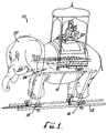
- the body 22 can be configured to resemble an animal, such as an elephant.
- the seating area 20 can be configured to resemble a howdah.
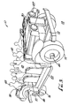
- the body 22 can be configured to resemble a transportation vehicle, such as an all terrain vehicle, a jeep, a car or truck, or various other forms of either on or off-road transportation vehicles.
- Various other body shapes may be employed as desired.
- the ride vehicle is moved along a path 18 that comprises a track.
- the track may take the form of a pair of parallel rails 25.
- the front and rear wheels 14 and 16 of the vehicle 10 can be suitably mounted for rolling engagement with these rails 25 in a conventional manner.
- An externally driven towing mechanism is provided as a driver to move the vehicle 10 along the rails 25.
- This driver may comprise an externally driven chain 27, as illustrated in FIGS. 1 and 2, or it may comprise a cable, platen drive system or other suitable arrangement.
- the ride vehicle 10 shown in FIGS. 1-2 also includes a controller 40 and a sound module 41 for generating sounds. These may be sounds corresponding to the sounds of the vehicle 10 interacting with the path, scenery and other props positioned at selected locations in, for example, an amusement attraction.
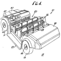
- the passenger seating area 20 includes several rows 26 of seats 28.
- Other seating arrangements can be used depending upon the theme involved, the size and shape of the body 22, and the particular type of ride experiences to be conveyed.
- the embodiment of the ride vehicle 10 illustrated in FIGS. 1-2, showing an elephant-shaped body 22 with a howdah for a seating area 20, is exemplary.
- Passenger restraints also can be provided to restrain the passengers and confine them safely in their seats during vehicle motion.
- a suitable passenger restraint system is disclosed and claimed in U.S. Pat. No. 5,182,836.
- the front portion of the body 22 includes a hood 30 which encloses the major power components of the vehicle, such as an electric motor 32, a hydraulic power unit 34 and a hydraulic propulsion motor 36.
- the hydraulic propulsion motor 36 corresponds to the driver that puts the chassis 12 in motion along the path 18.
- the drivers illustrated in the embodiments of FIGS. 1-2 (elephant body 22) and FIGS. 3-9 (vehicle body 22) are provided for purposes of illustration only and not by way of limitation.
- Other suitable drivers include linear induction motors, combustion engines, electric motors, cables, platen drives, and other suitable propelling devices, including gravity.
- the rear portion of the body 22 includes a trunk area 38 enclosing a controller 40 and a sound module 41 for generating sounds. These may be sounds corresponding to the sounds of the vehicle 10 interacting with the path 18, scenery 42 and other props positioned at selected locations in, for example, an amusement attraction. Further details regarding the vehicle's power components, controller 40, sound module 41, scenery 42 and other features are discussed in more detail below.
- the chassis 12 has a front axle 44 and a rear axle 46, with the front and rear wheels 14 and 16 connected to the opposite ends of each axle, respectively.
- Each wheel 14 and 16 is equipped with a suitable tire, such as an inflatable tire or the like. Braking of the ride vehicle 10 when parked is carried out with spring applied, hydraulic release fail-safe disc brakes on all four wheels. If system power fails, spring energy causes the brakes to "fail" on.
- the front wheels 14 and the rear wheels 16 each have a separate steering system which allows the front wheels 14 and the rear wheels 16 to be steered independently of each other. This provides a steering system that is capable of producing a yaw axis of motion for the vehicle 10. This enables various motion patterns of the vehicle 10 not capable with conventional front wheel steering vehicles.
- the motion apparatus 24 is integrated into the chassis 12 for imparting motion in one or more degrees of freedom to the body 22 relative to but independent of the chassis 12.
- This relative motion of the body 22 with respect to the chassis 12 can be provided whether or not the chassis is in motion.
- the motion apparatus 24 can raise the body 22 and tilt it along several axes of motion to substantially enhance the sensation of vehicle movement experienced by passengers 48 riding in the vehicle 10.
- motion of the body 22 with respect to the chassis 12 can be designed to enhance the sensation of vehicle movement that is actually taking place.
- such motion can be designed to provide the passengers 48 with a realistic moving ride vehicle experience which is actually not taking place.
- FIGS. 5-9 One form of the motion apparatus 24 is illustrated in FIGS. 5-9, with various details of the vehicle body 22 and chassis 12 having been omitted for purposes of clarity and simplification.
- This embodiment of the motion apparatus 24 uses three hydraulic servo actuators comprising a left-front motion base servo actuator 50, a right-front motion base servo actuator 52 and a rear motion base servo actuator 54.
- the motion apparatus 24 also includes a body support platform or frame 56 securely connected to or integrated with the body 22 so as to form the underside of the body 22. All three of the actuators 50, 52 and 54 have their lower ends pivotally connected to a base portion 58 of the chassis 12 by separate mounting brackets 60.
- mounting brackets 60 are also used to pivotally couple the upper ends of the actuators 50, 52 and 54 to the body support frame 56 (i.e., to the body 22). Each of these brackets 60 is adapted to receive a fastener 62 to secure the actuators 50, 52 and 54 to the mounting brackets 60. As seen in FIG. 3, for example, two of the actuators 50 and 52 in this embodiment are forwardly mounted and have their upper ends pivotally connected directly to the front portion of the body support frame 56 by separate brackets 60. The third actuator 54 is mounted rearwardly of the other two and has its upper end pivotally connected to the rear portion of the body support frame 56.
- the motion apparatus 24 also comprises two motion control arms comprising an A-arm 64 and a scissors 66.
- the A-arm 64 preferably is a bolted steel structure
- the scissors 66 preferably is a welded tubular steel frame.
- the A-arm 64 has its front end pivotally connected by brackets 68 to the front end of the vehicle chassis 12 and its rear end pivotally connected by brackets 70 to the rear portion of the body support frame 56 adjacent to the rear motion base servo actuator 54.
- the scissors 66 comprises a folding linkage in the form of two links 72 and 74 connected together at a pivot point 76.
- the lower end of the scissors 66 is pivotally connected by a bracket 78 to the chassis 12 adjacent to the two front motion base servo actuators 50 and 52.
- the upper end of the scissors 66 is connected by a bracket 80 to the front portion of the body support frame 56 adjacent to the two front motion base servo actuators 50 and 52.
- universal joints 82 are employed to connect the body support frame 56 to the rear end of the A-arm 64 and the upper end of the scissors 66.
- the A-arm 64 is adapted to be pivoted up and down about the pivot points where the A-arm is connected to the chassis 12, while the body support frame 56 is adapted to be rolled from side to side about the pivot points where the frame is connected to the A-arm 64 and scissors 66 by the universal joints 82.
- This configuration of the motion apparatus 24 allows the body 22 to be rolled from side to side about an imaginary roll axis, pitched forward and backward about an imaginary pitch axis, and elevated or heaved up and down with respect to the chassis 12.
- the A-arm 64 constrains longitudinal forward and rearward shifting (surge), lateral side to side shifting (slip) and yaw movement of the body 22 with respect to the chassis 12.
- the motion apparatus 24 uses three hydraulic servo actuators , but in a reverse orientation from that described above.
- the motion apparatus 24 comprises a front motion base servo actuator 29, a rear-left motion base servo actuator 31, and a rear-right motion base servo actuator 33.
- the motion apparatus 24 may comprise six actuators arranged in combinations of two to form a 2 + 2 + 2 motion base arrangement.
- the body 22 may be rolled from side to side, pitched forward and backward and heaved up and down with respect to the chassis, as in the embodiments of the motion apparatus of FIGS. 1-2 and FIGS. 3-9.
- Other motion capabilities with these six actuators include longitudinal forward and rearward shifting (surge), lateral side to side shifting (slip) and yaw movement of the body 22 with respect to the chassis 12.
- Another alternative form of the motion apparatus 24, for example, can include six actuators forming a 3 + 3 motion base arrangement, with three of the actuators rearwardly mounted and three forwardly mounted.
- This configuration of the motion apparatus 24 allows pitch, roll and heave of the body 22 with respect to the chassis, as in the embodiments of the motion apparatus of FIGS. 1-2 and FIGS. 3-9.
- Other movements include surge, slip and yaw movement of the body 22 with respect to the chassis 12.
- three actuators can be arranged in a 1 + 2 motion base arrangement, in combination with a Watts linkage, to allow body movement with respect to the chassis 12 similar to that described above in connection with the embodiments of FIGS. 1-2 and FIGS. 3-9.
- the Watts linkage constrains surge, slip and yaw movement of the body 22 with respect to the chassis 12.
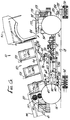
- FIG. 5 is a side elevational view, partly in cross-section, showing the body 22 in a normal, horizontal position relative to the chassis 12. In this position, each of the motion base servo actuators 50, 52 and 54 is retracted to a totally collapsed condition such that the ride vehicle 10 appears to resemble any other typical roadway vehicle.
- the motion apparatus 24, including its actuators 50, 52 and 54 and other controls, is adapted to react to a wide range of motion commands, including high accelerations, low velocities, smooth transitions and imperceptible washout to a static condition.
- the motion apparatus 24 preferably is designed to be interchangeable from one vehicle to another, as are all of the other components of the ride vehicle 10 described herein.
- the motion apparatus 24 is intended to replicate a broad range of vehicle motions during a ride. As explained in more detail below, these motions can be programmed in conjunction with an amusement park attraction or other environment to provide a unique ride experience to the passengers 48. Moreover, each vehicle 10 is adapted to store more than one motion pattern so that the vehicle ride and action is not necessarily the same from one ride to the next. The motion patterns are programmed and stored by a ride programmer during the development of an attraction with the aid of a separate programming console (not shown). This programming console is then used to directly download programmed data to the vehicle's on board controller 40.
- the body 22 When the ride first starts, the body 22 usually will be in the fully settled or down position, as shown in FIGS. 1 and 3-5, to allow the passengers 48 to unload and load. In this position, the motion base servo actuators 50, 52 and 54 are fully collapsed and the forces of gravity can move the body 22 to the down position. If desired, the actuators 50, 52 and 54 can be commanded to go to a collapsed condition when it is necessary to quickly move the body 22 to the down position, such as at the end of the ride.
- FIGS. 6-9 show examples of the range of motion of the body 22 with respect to the chassis 12.
- the motion apparatus 24 is capable of providing motion in three degrees of freedom to provide body movements with respect to the chassis 12.
- FIG. 6 shows the body 22 pitched in a rearward direction about the pitch axis of the vehicle 10.
- the two front actuators 50 and 52 provide movement of the body 22 in this manner, while the rear actuator 54 is moved only slightly or not at all.
- Power for movement of the actuators 50, 52 and 54 is derived from the on-board vehicle hydraulic system and position sensors 84 on the actuators that provide the position of the body 22 to the on-board controller 40.
- these sensors 84 are a non-contact, absolute position, magnetostrictive-type sensor. Using the sensors 84, the degree of pitch of the body 22 with respect to the chassis 12 may be accurately controlled as desired. In the one embodiment, the body 22 can be pitched rearwardly by as much as 15.9 degrees.
- FIG. 7 shows the body 22 pitched in a forward direction relative to the chassis 12.
- This pitching motion is achieved by supplying appropriate hydraulic power to the rear actuator 54 to raise the rear end of the body 22, while the two forward actuators 50 and 52 are moved only slightly or not at all.
- This forward pitching motion of the body 22 with respect to the chassis 12 occurs about the pitch axis of the vehicle 10.
- the body 22 can be pitched forward by as much as 14.7 degrees.
- the movement of the actuators 50, 52 and 54 causes either a constant velocity movement or rotational acceleration of the body 22 with respect to the chassis 12 about the pitch axis.
- FIG. 8 shows all three actuators 50, 52 and 54 in a fully extended position, raising the body 22 to an elevated, horizontal position with respect to the chassis 12. This is accomplished by supplying appropriate hydraulic power to all three actuators 50, 52 and 54 so that they are fully extended.
- the body 22 can be elevated or heaved by as much as 15 inches above the chassis.
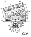
- FIG. 9 is a front elevational view of the vehicle 10, showing the body 22 rolled with respect to one side of the chassis 12. This is accomplished by supplying appropriate hydraulic pressure to the actuators 50, 52 and 54, resulting in rotational movement of the body 22 with respect to the chassis 12 about the roll axis of the vehicle 10. In this condition, one of the two front actuators 50 is extended while the other actuator 52 is collapsed. The rear actuator 54 also is partially extended to the extent necessary to accommodate extension of the one front actuator 50. In one embodiment, the body 22 can be rolled by as much as 16.1 degrees to either side of the chassis 12. Again, it will be understood that various intermediate ranges of motion, and motion in the opposite direction to that shown in FIG. 9, are possible about the roll axis of the vehicle 10.
- the body 22 can be both pitched forward and rolled to one side with respect to the chassis 12 by as much as 8.2 degrees (pitch) and 15.4 degrees (roll).
- the body 22 can be both pitched rearward and rolled to one side with respect to the chassis 12 by as much as 7.2 degrees (pitch) and 17.4 degrees (roll).
- FIGS. 10-12 show a bogie apparatus 86 for connecting the ride vehicle 10 to underground track rails 88 below the surface of the path 18 upon which the vehicle 10 travels.
- there are two bogies comprising a front bogie 90 and a rear bogie 92.
- These bogies 90 and 92 have several common features.
- each of the bogies 90 and 92 has several sets of wheels for rolling engagement with a pair of spaced, parallel rails 88 positioned under the path or surface 18 on which the vehicle 10 travels. As explained below, these sets of wheels securely attach the bogies 90 and 92 to the rails 88.
- the front bogie 90 also is provided with two bus bar collectors 94 per bus rail. These bus bar collectors 94 are spring tensioned to maintain the necessary contact forces between the collector 94 and a bus bar 95 to provide the A.C. electrical power used to drive the electric motor 32 and control system signals for the ride vehicle 10.
- Each bogie 90 and 92 has a multiple wheel arrangement comprising load wheels 96, up-stop wheels 98, static guide wheels 100 and active guide wheels 102.
- the load wheels 96 of which there are four, ride on the top of the track rails 88 and support the weight of the bogies 90 and 92.
- the up-stop wheels 98 which also are four in number, are located on the bottom of the bogies 90 and 92 and inhibit upward motion. These wheels 98 preferably are designed with a small clearance relative to the rails 88 so as not to add to the rolling resistance of the bogie 90 or 92.
- two active guide wheels 102 mounted on pivoting arms 104 pre-load and center the bogie 90 or 92 and also inhibit lateral motion of the bogie into the side of the opposing track rail 88.
- Each of these wheels 104 also is provided with a spring tensioner 106 for the pre-loading and centering function.
- the front bogie 90 is connected to the vehicle's front steering system and, therefore, is subjected to front steering loads.
- the rear bogie 92 is essentially free of normal operating loads, other than its own weight, and is towed along the track through its connection to the vehicle's lateral energy absorbing system described below.
- the bus bars 95 have a 200 amp capacity. These bus bars 95 also preferably have a stainless wear surface, such as aluminum. For example, the Wampfler Model 812 bus bar has been used and found to be suitable.
- the bus bar collectors 94 preferably have a wear surface comprising copper graphite.
- the bus bars 95 may be installed in an open downward position to prevent debris from entering the bars and shortening their life.
- the vehicle's front wheels 14 are steered in one embodiment via a mechanical steering system that uses the curvature of the path 18 to steer the front wheels. More particularly, the two front wheels 14 are connected to the chassis 12 for rotation by the front axles 44, using zero king pin inclination. The two front wheels 14 also are linked together by a linkage arm 108, such that turning motion of one front wheel 14 is automatically transferred via the linkage arm 108 to the other front wheel 14. The two ends of the linkage arm 108 are connected to the front wheels 14 by conventional ball and joint connections 110.
- One of the front wheels 14, such as the right-front wheel, is connected by a steering bar 112 to an upper steer arm 114 via ball and joint connections 116.
- the upper steer arm 114 is connected by a vertical spline shaft 118 to a lower input arm 120 such that horizontal pivoting motion of the lower input arm 120 about the axis of the vertical spline shaft 118 is directly translated into corresponding horizontal pivotal movement of the upper steer arm 114.
- the lower end of the spline shaft 118 is pivotally connected to the lower input arm 120 to accommodate up and down movement of the lower input arm caused by the grade of the path 18.
- the lower input arm 120 is, in turn, bolted to the front bogie 90 via a front follower 122 and a plain spherical bearing 124.
- steering of the rear wheels 16 is independent of steering of the front wheels 14 to increase the versatility of motion of the ride vehicle 10.
- the steering of each rear wheel 16 is controlled by separate hydraulic steering servo actuators 126.
- These steering actuators 126 are connected to the hydraulic control system of the vehicle 10 and are controlled by the controller 40 in combination with feedback signals from sensors 128 to control the movement of the actuators 126 and, thus, the steering of the rear wheels 16.
- FIGS. 18 and 19 show the range of steering motion of the rear wheels 16 in more detail.
- the inner ends of the steering actuators 126 are mounted to the vehicle's rear axle beam 130 by brackets 132 with pivotal connections.
- the outer ends of the steering actuators 126 are mounted to trunion mountings 134 at the rear axle 46 via plain bearings.
- the trunion mounting 134 for the actuators 126 incorporates motion in two axes to allow for build tolerances.
- the steering actuators 126 are controlled by the hydraulic control system through appropriate tubing.
- the steering of the front wheels 14 may be carried out in the same manner as the steering of the rear wheels 16, by using separate front steering servo actuators 135.
- the front steering actuators 135 also are connected to the hydraulic control system of the vehicle 10. These actuators 135 are controlled by the controller 40 in combination with feedback signals from sensors 137 to control the movement of the actuators 135 and, thus, the steering of the front wheels 14. Using this arrangement, the steering of the front wheels 14 is independent of the curvature of the path 18 followed by the vehicle 10.
- the foregoing embodiments which provide independent steering of the front wheels 14 and the rear wheels 16, allow a wide range of vehicle motion not otherwise possible with conventional ride vehicles, which have either had front wheel steering or rear wheel steering (but not both), or no steering capabilities at all for vehicles that are totally track dedicated.
- vehicle motion enabled by four-wheel steering include the simulated effect of the vehicle 10 fishtailing, such as during rapid acceleration or deceleration of the vehicle, or sliding sideways as on ice or an oil slick.
- the turning of corners can also be exaggerated by using four-wheel steering, which substantially enhances the general overall mobility and turning capabilities of the vehicle 10. These and other vehicle movements are described later.
- FIGS. 13 and 18-19 also illustrate a lateral energy absorbing system of the vehicle which allows the vehicle 10 to move laterally with respect to the rear bogie 92 within a pre-determined tracking envelope during movement of the vehicle 10 along the path 18.
- the lateral energy absorbing system absorbs lateral loads and, under certain conditions, completely disables operation of the vehicle 10. In this way, the passengers 48 in the vehicle will not be subjected to unsafe accelerations, jerks or other violent movements of the vehicle beyond specified limits, to help ensure the passenger's safety.
- the lateral energy absorbing system comprises a rear follower lockout actuator 136 pivotally connected to the chassis 12 by a pivot shaft 138 and to the rear bogie 92 via a spherical bearing 140 on a rear follower 142.
- the lockout actuator 136 is designed to operate in two distinct modes related to the degree of curvature of the vehicle's path 18.
- the path 18 shown in FIGS. 18-19 comprises a channel forming a roadway that allows some lateral movement of the dynamic ride vehicle 10.
- the lockout actuator 136 is designed to operate in a first mode when the vehicle 10 follows a path 18 where it is permitted large rear offset, as shown in FIG. 19. In the first mode, the lockout actuator 136 is in a fully retracted position. In this fully retracted position, an energy absorbing pad 142 at the rear portion of the actuator 136 is laterally confined between two vertical plates 143 spaced apart by a first distance on the chassis 12.
- the lockout actuator 136 is designed to operate in the second mode when the vehicle 10 follows a path 18 where there is a relatively narrow clearance that requires restriction of rear offset, as shown in FIG. 18.
- the lockout actuator 136 In the second mode, the lockout actuator 136 is in a fully extended position. In this fully extended position, the energy absorbing pad 142 at the rear portion of the lockout actuator 136 is laterally confined between two oppositely facing vertical blades 145 on the chassis 12 which are spaced apart by a second distance that is smaller than the first distance previously described.
- the energy absorbing pad 142 will contact either the vertical plates 143 or the vertical blades 145 on the chassis 12 to prevent further lateral movement.
- two piston-type sensors 147 coupled to the lockout actuator 136 will be activated to cause an E-stop and completely disable the vehicle 10.
- the ride vehicle 10 can be wire-guided or completely autonomous.
- the ride vehicle 10 also can be designed to travel along the path 18 without being physically linked to a front or rear bogie 90 or 92, or physically constrained within a predetermined tracking envelope.
- the ride vehicle may be guided using radar, sonar or infrared guidance systems.
- FIG. 20 is a block diagram that illustrates one example of a hydraulic control system for providing hydraulic power to the various actuators and other components of the ride vehicle 10.
- a suitable power supply tapped from the bus bar 95 drives the electric motor 32, which in turn drives the hydraulic power unit 34.
- the hydraulic power unit 34 is responsible for providing the energy for all of the vehicle's actuators, and to operate the hydraulic propulsion motor 36.
- the output of the propulsion motor 36 is transferred by couplings 151 and a centering shaft 153 to a differential ratio gear box 155 to produce an output for driving the front wheels 14.
- the propulsion motor 36 may comprise a variable displacement hydraulic motor with a tachometer to measure the propulsion motor's output shaft rpms. This information is sent to the vehicle's controller 40 which monitors a motor overspeed condition, while stroke displacement transducers govern hydraulic displacement of the propulsion motor's pistons to provide for controlled acceleration, deceleration and velocity of the vehicle 10.
- FIG. 5 shows the location of these accumulators 157 at the rear of the ride vehicle. These accumulators are used for ride vehicle propulsion, actuation of the motion base 24 and for steering of the rear wheels 16.
- the hydraulic power unit 34 supplies this hydraulic energy by pumping hydraulic fluid through a pressure filter 159 through a central manifold 161 and subsequently to the high pressure accumulators 157.
- the primary function of the high pressure accumulators 157 is to store and save energy for supply on demand to the various energy users of the hydraulic system.
- These energy users comprise the hydraulic motor 36, the left-front motion base servo actuator 50, the right-front motion base servo actuator 52, the rear motion base servo actuator 54, the right-rear steering servo actuator 126, the left-rear steering servo actuator 126 and the rear follower lockout actuator 136.
- Each of these actuators, except for the follower lockout actuator 136, has a servo valve which controls the flow of pressurized hydraulic fluid to the actuators according to a command from the controller 40.
- the hydraulic control system also includes a back pressure valve 163 that maintains a predetermined amount of back pressure in a low pressure accumulator 165.
- the low pressure accumulator 165 is designed to store extra hydraulic fluid that may be needed by the hydraulic power unit 34 when the vehicle 10 is decelerating.
- An anti-cavitation valve 169, a return filter 171 and a heat exchanger 173 also are provided to complete the hydraulic control system.
- a cooling fan 175 and a shroud 177 direct airflow through the heat exchanger 173 and over the electric motor 32 for cooling purposes.
- the hydraulic control system also is used to control operation of the vehicle's emergency/parking brakes.
- These brakes comprise a right-front brake 179, a left-front brake 181, a right-rear brake 183 and a left-rear brake 185.
- hydraulic fluid is withdrawn from the brakes through a return line to the central manifold 161 and return filter 171. This releases brake springs and applies pressure to cause full braking action.
- hydraulic fluid is supplied to the brakes to compress the springs and remove braking pressure.
- vehicle deceleration is ordinarily perform by driving the swashplate of the propulsion motor 36 to a negative angle, thereby using the vehicle's kinetic energy to recharge the high pressure accumulators by pumping hydraulic fluid into it from the low pressure accumulator.
- the wayside interface uses the power bus 97 (FIG. 11), to control vehicle power by track segment, and also radio frequency (rf) communication to interact with computers on each vehicle 10. Other forms of communication may be provided, for example, by using bus bar signals, infrared communication or the like.
- the vehicle computers two per vehicle, are responsible for conducting the ride experience, which may be distinct for each vehicle 10. More details about vehicle control will be discussed further below.
- the power bus 97 is comprised of six adjacent bus bars 95, three just left of the center of the track 18 and three just to the right of the center of the track.
- the left three bus bars 95 supply four hundred eighty volts in three phases for meeting each vehicle's power requirements.
- the power bus 97 supplies electric power that drives each vehicle's other electric elements, for example, the hydraulic power unit 34, the cooling fan 175, and peripherals, including headlights 187 and the sound module 41.
- the three bus bars 95 just right of center provide a ground, a twenty-four volt "go" signal and a twenty-four volt variable impedance "no-go" signal (which indicates proximity of another vehicle), all signals being specific to track segment. That is, if there is a stoppage, the wayside interface can remove the "go" signal from a track segment and cause the vehicle 10 to execute a "hold-pattern," if desired.
- each vehicle 10 carries a radio frequency (rf) transceiver 191 and two on-board computers 193 and 195, which are identical in software, and which are utilized in parallel for safety purposes, as part of a "voting" implementation.
- One computer 193, called the ride control computer (“RCC”) controls the audio aspects of the ride experience and the servo-control elements 197 that control propulsion and vehicle motion.
- RCC ride control computer
- Both the RCC 193 and its companion ride monitor computer 195 (“RMC”) are separately coupled to the rf transceiver 191 and to parallel sensors and bus controls utilized for vehicle control.
- the computers 193 and 195 communicate with each other regarding vehicle faults, action and status, by the voting scheme, and alert the wayside interface if there is a disagreement between the two computers, indicating a logic fault, or an agreement about a serious status that requires vehicle shutdown, for example, critical overheating.
- both computers 193 and 195 wait a specific time period to receive a related signal from their companion computer before reaching a conclusion as to agreement or disagreement, mostly necessitated due to tolerance differences between different sensors used in parallel by each computer. Should a serious condition develop, the wayside interface automatically disables the twenty-four volt "go" signal for the particular segment of the track, or may implement the emergency stop signal.
- each computer 193 and 195 carries its own memory 189, which contains all the program information necessary to run a plurality of different ride programs, and to synchronize actions of the ride vehicle with motion of the vehicle, audio sounds, or the external environment, or sets.
- Each program is stored in a plurality of program portions, each consisting of commands may be both time-based and track-position-based.
- the vehicle computers 193 and 195 may independently determine when and where a particular command is to be executed during the ride, and confirm this determination and resultant vehicle reaction with the other computer.
- Each command of each ride program includes a number of digital data values, or sub-commands, including vehicle velocity, motion base position for each of three axes, offset for the rear of the vehicle, audio cues, vehicle headlights on and off, and safety functions, including rear follower offset lock-out.
- each ride computer 193 and 195 possesses a math co-processor 201 which performs all floating point calculations.
- both the RCC 193 and the RMC 195 are nearly identical in architecture and operate in parallel, and both are represented by the reference numeral 203 in FIGS. 21A and 21B.
- FIGS. 21A and 21B generally show the architecture and wiring of one of the computers 203 (RCC and RMC) to the various sensors and controls utilized by the vehicle.
- Each computer has a CPU 205 that includes a microprocessor for monitoring vehicle sensors and directing communications, voting, and activities of the servo-mechanisms.
- a real-time clock 207 is utilized for computation of time based segments and overall system control.
- each computer 203 features a modular E 2 PROM board 211 which includes memory for storing ride programs which may be accessed or edited or rewritten.
- the math co-processor board 201 is provided for the CPU 205 to perform floating point calculations.
- Each computer 203 also possesses several serial ports 213 and a set of high speed counter inputs 215 and digital and analog I/O boards 217 and 219, for monitoring vehicle sensors and providing digital control signals.
- the RCC 193 has digital output signals from its digital I/O board 217 actually wired to provide control signal outputs.
- servo-mechanism control is supplied by a servo-control board 221 having servo-outputs and feedback inputs, collectively designated by the reference numeral 223.
- the servo-control board 221 is preferably installed only in the RCC 193, and linear sensors are used to provide analog signal inputs to both computers, to enable them to monitor the response of the various mechanical elements of the vehicle.
- Both computers 193 and 195 are coupled to the bus controls 239, 241, 257 and 259, to thereby selectively disable digital control of the vehicle's mechanical elements, such as the motion base, in the event of a vehicle shut-down.
- the bus controls are coupled to the digital I/O board 217 of the RCC 193, such that if either computer disables digital control, the RCC 193 is no longer capable of directing actuation of mechanical elements.
- the front bogie of the ride vehicle mounts two of the position sensors 99 on each side, for a total of four track position proximity-type update sensors. These sensors sense the proximity of path-mounted position markers, each consisting of a number of metal targets 101 mounted within the track, just below the front bogie, as seen in FIG. 9.
- two idler wheels 103 of the front bogie are used as redundant incremental longitudinal position sensors, in the form of rotary encoders.
- These encoders each a quadrature sensor, provide 360-pulse-per-rotation 90-degree phase-shifted output signals, which are coupled to a velocity polarity sensor (which detects forward and reverse velocity) and to high-speed counter inputs 215.
- These inputs 215 are read and formatted to a total distance measurement, in feet, by the computerized vehicle-control system 40, and are loaded into a distance register.
- the ride vehicle 10 keeps track of incremental distance using the idler wheels 103, and uses the update sensors 99 to detect the presence of the path-mounted position markers to detect and correct errors in the tracked position of the ride vehicle.
- a logic error is ascertained by the controller 40 if position errors exceed a relatively small quantity, or if the counter inputs 215 differ by more than a predetermined amount.
- the idler wheels 103 are utilized instead of a tachometer, which may be subject to error occasioned by slippage and wear of the wheels 14 of the ride vehicle 10.
- the high speed counter inputs 215 are reset each time that they are read by the CPU 205, and the incremental position measurement is expected to be sufficiently accurate that the position markers may be spaced at great distances, for infrequent detection and update of the incremental position measurements.
- Each vehicle command stored in each computer's memory 189 may also include audio cue information.
- numerous sounds can be generated by the vehicle 10, including different engine pitches, screeching tires and brakes. It will be appreciated that various other sounds can be generated as desired to create a particular audio effect. These sounds are directed to, and are actually produced by, speakers 247 located below the passengers seats to simulate sounds that emanate from the vehicle, including from the engine compartment and the wells of the vehicle's wheels 14 and 16. In addition to the speakers 247 on the vehicle 10, other speakers (not shown) also may be placed at strategic locations along the path 18 followed by the vehicle. As illustrated in FIG. 22, the RCC 193 is coupled to an audio processor and sequencer 249 to which it feeds the audio signal information used to generate vehicle and other sounds associated with the particular ride experience.
- the actual sounds and actions reproduced by the vehicle 10 are created during a programming state, in which a programmer plugs a programming console (not shown) into the vehicle, and uses the console to direct the vehicle's activities.
- These programmed sounds are initially time-based, and are recorded in digital format, much as music would be recorded by a tape machine. Once the time-based actions are generated, they may be sequenced by defining recorded actions to occur at a specific position along the path 18.
- additional time-based and position-based routines are preferably configured to be run when the vehicle 10 is in a "hold-pattern," that is, when the vehicle is stopped, the vehicle may implement a motion sequence where only the motion apparatus 24 of the vehicle 10 is used, or certain audio sounds, such as engine-revving, are generated, etc.
- vehicle actions are recorded in a digital format, preferably using a disk operating system ("DOS"), and stored in a software file which may be readily sequenced and edited.
- the amusement ride vehicle 10 is capable of enhancing the sensation of vehicle movement that is actually taking place, as well as providing the passengers with realistic moving ride vehicle experiences that are not actually happening. Even when travelling along a path 18 without scenery, props, audio or other special effects, the ride vehicle 10 can be made to execute several motion patterns, or sequences of motion patterns. These patterns can be programmed into the controller 40, or alternatively, provision can be made for motion control in response to manual control of the vehicle 10 or other manual command.
- a motion pattern is defined as a sequence of movements by the motion apparatus 24 and its corresponding actuators 50, 52, 54 and 126 and/or 135 that cause the body 22 to move in a repeatable path in relation to the chassis 12, and which may occur while the chassis 12 is stationary or in motion along the path 18.
- the resulting motion pattern gives the passengers 48 a sensation that the vehicle 10 is undergoing directional maneuvers or surface conditions which may or may not actually be present.
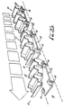
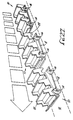
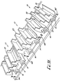
- FIGS. 23-34 illustrate examples of some of the basic motion patterns executed by the ride vehicle 10.
- FIG. 23 shows a motion pattern in which the ride vehicle 10 is in various stages of turning a corner 144.
- the sensation of turning the corner 144 is exaggerated by outward body roll relative to the chassis 12. This is accomplished by rotational acceleration of the body 22 with respect to the chassis 12 about the roll axis of the vehicle 10.
- the vehicle 10 Prior to initiating the turn, the vehicle 10 is moved forward along the path 18 with the body 22 in a substantially level position with respect to the chassis 12.
- the body 22 is simultaneously accelerated about the roll axis, in an outward direction with respect to the curved path 18, as indicated by the motion arrows 146.
- the degree of outward body roll is increased until it reaches a maximum at the point where the vehicle is substantially at the apex of the curved path 18. This has the effect of exaggerating and enhancing the passenger's sensation of the speed and sharpness of the corner 144, thereby supplementing the normal sensations that would be experienced by the passenger when turning a corner in the absence of the outward body roll.
- the body 22 is rolled back inwardly until it reaches a substantially level position with respect to the chassis 12, at the end of the turn.
- the motion pattern described above simulates the gross movements of a vehicle turning sharply at a high rate of speed.
- a maneuver normally would be accompanied by an effect called "wheel hopping".
- Wheel hopping occurs under high lateral loads when tires alternately skid across the pavement and then grab the pavement in quick succession.
- This wheel hopping effect can be simulated very closely in the ride vehicle 10 by appropriate actuation of the motion base servo actuators 50, 52 and 54. These actuators can be manipulated to cause up and down movement of the body 22 during the turning of the corner 144 which simulates the wheel hopping sensation.
- motion patterns simulates the feeling of the texture or roughness of a road.
- Providing the servo actuators 50, 52 and 54 with a noise signal while the chassis 12 is in motion produces the perception of road roughness.
- the road roughness illusion is improved by making the frequency of the noise proportional to the vehicle's actual or simulated speed.
- the degree of roughness simulating for example the difference between a gravel road and a stony riverbed, is simulated by the amplitude of the noise.
- the dynamic ride vehicle 10 is intended to simulate the motion of an animal, another effect which can be added to various motion patterns simulates the gait of the animal as it would be perceived by a rider.
- a rough four phase motion could be programmed to simulate a trot, while a smoother two phase motion would simulate a gallop.
- FIG. 24 shows the ride vehicle 10 in various stages of turning a corner 144 with an inward body roll.
- the vehicle 10 is moved along the path 18, prior to initiating the turn, with the body 22 in a substantially level position with respect to the chassis 12, similar to the motion pattern described above in connection with FIG. 23.
- the body 22 is simultaneously accelerated about the roll axis in an inward direction with respect to the curved path 18, as indicated by the motion arrows 148.
- the degree of inward rolling movement of the body 22 reaches a maximum point at the apex of the curved path 18.
- FIG. 25 shows another motion pattern in which the ride vehicle 10 is in various stages of turning a corner 144.
- the turning sensation experienced by the passengers is exaggerated by four-wheel steering, rather than by outward body roll as shown in the motion pattern of FIG. 23.
- the vehicle 10 is moved forward along the path 18, and the body 22 is kept in a substantially level position with respect to the chassis 12 at all times throughout the turn.
- the rear wheels 16 of the vehicle 10 are steered away from the direction of the turn. This causes the back end of the vehicle 10 to accelerate and swing outwardly during the turn, as indicated by the motion arrows 150, to give the simulated effect of sliding.
- the front wheels 14 substantially follow the curvature of the turn 144.
- the rear wheels 16 are steered back inwardly into the turn. This causes the back end of the vehicle 10 to accelerate and swing inwardly, as indicated by the motion arrow 152, and simulates the effect of further sliding of the vehicle 10 as it comes out of the turn 144.
- the wheels 14 and 16 can be made to steer straight ahead in preparation for the next motion pattern.
- FIG. 26 shows the ride vehicle 10 in various stages of forward acceleration, utilizing rearward body pitch to exaggerate the sensation of speed during acceleration. This is accomplished by rotational acceleration of the body 22 with respect to the chassis 12 about the pitch axis of the vehicle 10. In this motion pattern, the vehicle 10 is accelerated quickly in the forward direction along the path 18. As soon as the vehicle 10 begins accelerating, the body 22 is quickly pitched backward by accelerating and raising the front end about the pitch axis. This body motion has the effect of exaggerating and enhancing the passenger's sensation of the acceleration of the vehicle 10 beyond the normal acceleration experienced in the absence of such body-pitching motion.
- the body 22 When the vehicle 10 has substantially finished its forward acceleration, the body 22 is gradually pitched forward by dropping the front end until it reaches a substantially level position with respect to the chassis 12. It will be understood that forward acceleration of the vehicle 10 may occur from a standing start or while the vehicle is already in motion.
- FIG. 27 shows the ride vehicle 10 in various stages of decelerating or braking, as exaggerated by forward body pitch.
- the vehicle is quickly decelerated.
- the body 22 is quickly pitched forward with respect to the chassis 12 by accelerating and raising the rear end about the pitch axis.
- the body 22 is quickly pitched backward with respect to the chassis 12 by lowering the rear end to a substantially level position with respect to the chassis.
- FIG. 28 shows a motion pattern in which the ride vehicle 10 is moving in a forward direction with body motion designed to simulate the effect of traveling over a bump or other object.
- This motion pattern involves moving the vehicle 10 forward along the path 18 to a point corresponding to the location of an imaginary object 153.
- the body 22 is quickly pitched backward and then forward by causing the front end of the body to quickly raise up and then down with respect to the chassis 12 as the front of the vehicle passes the point corresponding to the location of the imaginary object 153. This simulates the effect of the front wheels 14 travelling over the object.
- the body 22 After waiting for an elapsed distance travelled by the vehicle 10 that corresponds to the rear of the vehicle 10 reaching the imaginary object 153, the body 22 is quickly pitched forward and then backward by causing the rear end of the body to quickly raise up and then down with respect to the chassis 12 as the vehicle continues to move forward passing the imaginary object 153. This simulates the effect of the rear wheels 16 traveling over the object 153.
- the pitching motion of the body 22 described above may be combined with outward body roll from one side to the other, as may be desired to achieve a particular effect.
- An example of body rolling from side to side is shown by the motion arrows 154 of FIG. 28.
- a further aspect of the motion pattern illustrated in FIG. 28 involves pitching the body 22 forward and backward for several cycles after the vehicle 10 has passed the imaginary object 153. This gives the passengers the sensation normally experienced after a vehicle travels over an actual object 153. Thus, as the distance between the vehicle 10 and the imaginary object increases, the amplitude of the pitching motion is decreased until the body 22 is returned to a substantially level position with respect to the chassis 12. The degree of body-pitching motion and the corresponding number of cycles and amplitude can be varied, depending upon the size of the object and the ride experience to be conveyed.
- FIG. 29 shows the ride vehicle 10 moving in a forward direction with body motion designed to simulate the effect of traveling over a dip or ditch.
- the vehicle 10 is moved forward to a point corresponding to the location of the imaginary dip.
- the rear end of the body 22 is raised up and then dropped back down as the vehicle passes the point corresponding to the location of the imaginary dip.
- This body motion simulates the effect of the front wheels 14 entering the dip.
- the front end of the vehicle is raised up and then moved back down as the vehicle continues to move forward passing the imaginary dip.
- This body motion simulates the effect of the rear wheels 16 traveling through the dip.
- the total experience conveyed by this motion pattern indicated by the motion arrows 155, is the simulated effect of going over a dip that is not actually present in the path 18 followed by the vehicle 10.
- the forward and backward pitching motion of the body 22 is continued for several cycles after the vehicle 10 passes the imaginary dip.
- this continuation of the pitching motion gives the passengers the sensation of being in a conventional vehicle having shock absorbers that dampen the vehicle's motion after traveling over the dip.
- the amplitude of the pitching motion of the body 22 with respect to the chassis 12 is decreased until the body is returned to a substantially level position at a predetermined distance from the imaginary dip.
- FIG. 30 shows the ride vehicle 10 moving in a forward direction with body motion designed to simulate the effect of climbing a hill.
- the body 22 is pitched backward by accelerating and raising the front end about the pitch axis, as indicated by the motion arrow 156.
- the body 22 is kept in this pitched position, and then both the front and rear end are raised together as the imaginary hill is climbed.
- the front end is kept at a fixed, elevated position while the rear end of the body 22 is raised until it reaches a position substantially level with respect to the chassis 12 at the end of the climb, as shown by the motion arrow 158.
- FIG. 31 shows the ride vehicle 10 moving in a forward direction with body motion designed to simulate the effect of descending a hill.
- This motion pattern which is essentially the reverse of the motion pattern of FIG. 30, involves moving the vehicle 10 forward along the path 18 with the body 22 in a substantially horizontal but elevated position with respect to the chassis, as indicated by the motion arrow 160.
- the imaginary hill is descended by initially pitching the body 22 forward by accelerating and lowering the front end about the pitch axis.
- the body 22 is kept in this pitched position as the imaginary hill is descended, while both the front and rear end are lowered together, as indicated by the motion arrows 162.
- the rear of the body 22 is dropped down until it reaches a position substantially level with respect to the chassis 12.
- FIG. 32 shows the ride vehicle 10 moving in a forward direction with body motion designed to simulate the effect of floating or flying.
- the vehicle 10 is moved forwardly along the path 18 while gently rolling and pitching the body 22 through rotational accelerations about the roll and pitch axes in a random fashion with respect to the chassis 12, as indicated by the motion arrows 164 and 166.
- the addition of audio and special effects in combination with this motion pattern can provide a realistic moving ride vehicle experience which is not actually taking place.
- FIG. 33 shows the ride vehicle 10 moving in a forward direction with four-wheel steering designed to simulate the effect of fishtailing.
- the vehicle 10 is initially moving forward along the path 18 in a substantially straight line.
- the rear wheels 16 are steered outwardly in one direction to initiate the fishtailing.
- the front wheels 14 are also steered outwardly in the same direction such that both the front and rear wheels 14 and 16 are steered simultaneously in one direction.
- Both wheels 14 and 16 are then steered quickly in the opposition direction. This causes the vehicle 10 to move back and forth in the yaw direction, while keeping the center of gravity of the vehicle in substantially a straight line.
- the motion pattern described above accurately simulates that effect.
- FIG. 34 shows the ride vehicle 10 moving in a forward direction with four-wheel steering designed to simulate the effect of side-to-side swaying.
- the vehicle 10 is initially moved forward along the path 18 in substantially a straight line.
- Both the front and rear wheels 14 and 16 are then steered simultaneously in one direction, causing the vehicle 10 to move to one side of the path 18.
- the wheels 14 and 16 are then straightened out momentarily to gradually move the vehicle 10 in the forward direction.
- both the front and rear wheels 14 and 16 are steered simultaneously in the opposite direction causing the vehicle 10 to gradually move to the other side of the path 18.
- This vehicle motion caused by four-wheel steering can be repeated for as long as desired to simulate the effect of side-to-side swaying.
- the dynamic ride vehicle 10 of the present invention provides several unique motion patterns that may be executed in various sequences in an amusement park attraction or other environment, along with appropriate scenery, audio sounds and various other special effects, to create a very unique ride experience for the passengers in the vehicle.
- the ride vehicle 10 is capable of enhancing the sensation of vehicle movement that is actually taking place, as well as providing the passengers with realistic moving ride vehicle experiences that are not actually happening.
Landscapes
- Engineering & Computer Science (AREA)
- Theoretical Computer Science (AREA)
- Aviation & Aerospace Engineering (AREA)
- Business, Economics & Management (AREA)
- Physics & Mathematics (AREA)
- Educational Administration (AREA)
- Educational Technology (AREA)
- General Physics & Mathematics (AREA)
- Motorcycle And Bicycle Frame (AREA)
- Toys (AREA)
Claims (77)
- Dynamisches Fahrzeug (10), das einen Fahrgast (48) zu einer Vergnügungsfahrt aufnimmt und das sich entlang eines Weges (18) durch eine zu dem Fahrzeug (10) externe Umgebung bewegt, umfassend:ein Chassis (12), das das Fahrzeug (10) entlang des Weges (18) in bezug auf die Umgebung selektiv bewegt;einen Körper (22), der den Fahrgast (48) trägt und der es dem Fahrgast (48) erlaubt, die Umgebung zu sehen, um dem Fahrgast (48) ein Erlebnis zu verschaffen;eine Bewegungseinrichtung (24), die den Körper (22) mit dem Chassis (12) verbindet und eine gelenkige Anbindung des Körpers (22) in bezug auf das Chassis (12) bereitstellt,gekennzeichnet durch eine programmierbare Steuerung (40), die die Bewegung des Körpers (22) und die Bewegung des Chassis (12) und die relative Bewegung zwischen dem Körper (22) und dem Chassis (12) gemäß einer vorbestimmten Sequenz von Bewegungsmustern entlang des Weges steuert, wobei die Steuerung (40) gemäß einer anderen vorbestimmten Sequenz von Bewegungsmustern entlang des Weges (18) reprogrammierbar ist, wobei die vorbestimmten Sequenzen von Bewegungsmustern mit der Umgebung zusammenhängen, um das Erlebnis der vergnügungsfahrt zu erhöhen.
- Dynamisches Fahrzeug nach Anspruch 1, gekennzeichnet durch einen Fahrer, der das Chassis (12) entlang des Weges (18) steuert.
- Dynamisches Fahrzeug nach Anspruch 2, gekennzeichnet durch wenigstens ein Rad (14, 16) auf dem Chassis (12), das vom Fahrer angetrieben werden kann, um so eine Bewegung des Chassis (12) zu erzeugen.
- Dynamisches Fahrzeug nach Anspruch 1, gekennzeichnet durch einen extern angetriebenen Zugmechanismus (27), der zur Erzeugung einer Bewegung des Chassis (12) geeignet ist.
- Dynamisches Fahrzeug nach Anspruch 1, gekennzeichnet durch einen Steuerungsmechanismus (112, 114, 116, 118, 126), wobei die Bewegungsrichtung des Chassis (12) durch den Steuerungsmechanismus gesteuert wird.
- Dynamisches Fahrzeug nach Anspruch 1, dadurch gekennzeichnet, daß wenigstens ein Rad (14, 16) steuerbar ist, um die Richtung der Bewegung des Chassis (12) zu kontrollieren.
- Dynamisches Fahrzeug nach Anspruch 6, dadurch gekennzeichnet, daß die Räder (14, 16) ein Paar von steuerbaren Vorderrädern (14) und ein Paar von Hinterrädern (16) sind.
- Dynamisches Fahrzeug nach Anspruch 6, dadurch gekennzeichnet, daß die Räder (14, 16) ein Paar von steuerbaren Vorderrädern und ein Paar von steuerbaren Hinterrädern (16) sind.
- Dynamisches Fahrzeug nach Anspruch 8, dadurch gekennzeichnet, daß das Paar von steuerbaren Vorderrädern (14) und das Paar von steuerbaren Hinterrädern (16) unabhängig voneinander in unterschiedliche Richtungen steuerbar sind.
- Dynamisches Fahrzeug nach Anspruch 1, dadurch gekennzeichnet, daß der Weg (18) eine Spur oder ein Kanal ist.
- Dynamisches Fahrzeug nach Anspruch 1, dadurch gekennzeichnet, daß die Bewegung des Fahrzeugs (12) durch ein drahtgeführtes System, ein signalgeführtes System oder ein autonomes System gesteuert wird.
- Dynamisches Fahrzeug nach Anspruch 1, gekennzeichnet durch einen Steuermechanismus (126) zum Steuern der Richtung der Bewegung des Chassis (12) entlang des Weges (18).
- Dynamisches Fahrzeug nach Anspruch 12, dadurch gekennzeichnet, daß der Steuermechanismus (126) von einem Fahrgast (48) im Fahrzeug (10) oder von der Steuerung (40) gesteuert wird.
- Dynamisches Fahrzeug nach Anspruch 1, dadurch gekennzeichnet, daß der Körper (22) ein automatisch gesteuerter themenbezogener Körper ist.
- Dynamisches Fahrzeug nach Anspruch 14, dadurch gekennzeichnet, daß der themenbezogene Körper ein Transportfahrzeug oder ein Tier darstellt.
- Dynamisches Fahrzeug nach Anspruch 1, dadurch gekennzeichnet, daß die Bewegungseinrichtung (24) wenigstens einen Aktuator (29, 31, 33, 50, 52, 54) aufweist, um den Körper (22) in bezug auf das Chassis (12) in Bewegung zu versetzen.
- Dynamisches Fahrzeug nach Anspruch 1, dadurch gekennzeichnet, daß die Bewegungseinrichtung (24) wenigstens einen Aktuator (29, 31, 33, 50, 52, 54) aufweist, der den Körper (22) von Seite zu Seite rollt, den Körper (22) von vorn nach hinten neigt, den Körper (22) in einer wesentlichen horizontalen Ebene verschwenkt, den Körper (22) nach oben und unten bewegt, den Körper (22) nach vorne und hinten reitet, den Körper (22) von Seite zu Seite verrutscht oder den Körper (22) gelenkig verschwenkt.
- Dynamisches Fahrzeug nach Anspruch 2, dadurch gekennzeichnet, daß die Steuerung (40) auch den Fahrer kontrolliert.
- Dynamisches Fahrzeug nach Anspruch 1, gekennzeichnet durch eine Bremse (179, 181, 183, 185) zum Abbremsen des bewegbaren Chassis (12).
- Dynamisches Fahrzeug nach Anspruch 19, dadurch gekennzeichnet, daß die Bremse (179, 181, 183, 185) von der Steuerung (40) gesteuert wird.
- Dynamisches Fahrzeug nach Anspruch 1, gekennzeichnet durch eine tonerzeugende Audioeinrichtung (41), wobei die Steuerung (40) die Audioeinrichtung (41) zur Erzeugung von Tönen steuert.
- Dynamisches Fahrzeug nach Anspruch 1, dadurch gekennzeichnet, daß die Steuerung (40) Steuersignale zu der Bewegungseinrichtung (24) in Echtzeit überträgt, um die Bewegung des Körpers (22) in bezug auf das Chassis (12) zu koordinieren.
- Dynamisches Fahrzeug nach Anspruch 1, dadurch gekennzeichnet, daß die Steuerung (40) Steuersignale als Reaktion auf ein extern zugeführtes Signal erzeugt.
- Dynamisches Fahrzeug nach Anspruch 23, dadurch gekennzeichnet, daß das extern zugeführte Signal von einem Fahrgast (48) auf dem Fahrzeug (10) oder von einer außerhalb des Fahrzeugs angeordneten Einrichtung erzeugt wird.
- Dynamisches Fahrzeug nach Anspruch 24, dadurch gekennzeichnet, daß die Steuerung (40) Information zu der außerhalb angeordneten Einrichtung überträgt.
- Dynamisches Fahrzeug nach Anspruch 23, dadurch gekennzeichnet, daß die Steuerung (40) der Bewegungseinrichtung (24) Steuersignale in Echtzeit überträgt, wobei die Steuersignale von der Bewegung des Chassis (12) abhängen.
- Dynamisches Fahrzeug nach Anspruch 26, dadurch gekennzeichnet, daß die erzeugten Steuersignale von der Geschwindigkeit des Fahrzeugs abhängen.
- Dynamisches Fahrzeug nach Anspruch 24, dadurch gekennzeichnet, daß die erzeugten Steuersignale von der Position des Fahrzeugs in bezug auf den Weg (18) abhängen.
- Dynamisches Fahrzeug nach Anspruch 1, dadurch gekennzeichnet, daß die Arbeitsweise der Steuerung (40) auf einer Zeitfunktion basiert.
- Dynamisches Fahrzeug nach irgendeinem der Ansprüche 1 bis 29, dadurch gekennzeichnet, daß die Steuerung (40) die Bewegung des Chassis (12) entlang des Weges (18) in bezug auf die Umgebung mit der Bewegung des Körpers (22) in bezug auf das Chassis (12) koordiniert, um ein bestimmtes Bewegungserlebnis für den Fahrgast (48) im Fahrzeug (10) zu erzeugen.
- Dynamisches Fahrzeug nach irgendeinem der Ansprüche 1 bis 30, dadurch gekennzeichnet, daß ein Speicher (189) vorgesehen ist, der eine Sequenz von Information zum Steuern der Bewegung der Bewegungseinrichtung (24) speichert, um den Körper (22) in eine Bewegung zu versetzen, die der dem Körper (22) durch die Bewegung des Chassis (12) entlang des Weges (18) erzeugten Bewegung überlagert ist;wobei die Steuerung (40) mit dem Speicher (189) verbunden ist, um hieraus Daten für die Sequenz der Information auszulesen und um die Bewegungseinrichtung (24) als Reaktion hierauf zu betätigen; undwobei ein Trigger vorgesehen ist, der ein Ereignis detektiert, das anzeigt, daß das nächste Stück von Information in der Sequenz von Information verwendet werden muß, um die Steuerung der Bewegungseinrichtung (24) zu steuern, und der als Reaktion hierauf die Betätigung der Bewegungseinrichtung (24) als Reaktion auf das nächste Stück von Information auslöst.
- Dynamisches Fahrzeug nach Anspruch 31, dadurch gekennzeichnet, daß(a) der Trigger einen Sensor (99) umfaßt, der mit der Steuerung (40) elektronisch gekoppelt ist; und(b) das detektierte Ereignis anzeigt, daß das nächste zu verwendende Stück von Information das Erreichen einer vorbestimmten Position entlang des Weges (18) durch das Fahrzeug (10) ist.
- Dynamisches Fahrzeug nach irgendeinem der Ansprüche 1 bis 32, dadurch gekennzeichnet, daß die Position des Fahrzeugs (10) durch den Empfang einer elektromagnetischen Übertragung von einer zu dem Fahrzeug externen Quelle bestimmt wird, die repräsentativ für die Position des Fahrzeugs ist, wobei der Sensor eine Antenne ist.
- Dynamisches Fahrzeug nach irgendeinem der Ansprüche 1 bis 32, dadurch gekennzeichnet, daß die Position des Fahrzeugs (10) durch Positionsindicia bestimmt wird, die extern zu dem Fahrzeug (10) sind.
- Dynamisches Fahrzeug nach irgendeinem der Ansprüche 1 bis 32, dadurch gekennzeichnet, daß die Position des Fahrzeugs (10) durch einen inkrementalen Positionsanzeiger bestimmt wird, der von der Steuerung (40) verwaltet wird.
- Dynamisches Fahrzeug nach irgendeinem der Ansprüche 1 bis 32, dadurch gekennzeichnet, daß die Position des Fahrzeugs (10) annähernd in bezug auf eine abgelaufene Zeit von einer vorbestimmten Referenzzeit bestimmt wird, wobei der Sensor eine Uhr ist.
- Dynamisches Fahrzeug nach irgendeinem der Ansprüche 31 bis 32, dadurch gekennzeichnet, daß der Speicher (189) ein elektronischer Speicher ist, der eine Mehrzahl von unterschiedlichen Sequenzen von Information enthält, die alternativ ausgewählt werden.
- Dynamisches Fahrzeug nach Anspruch 37, dadurch gekennzeichnet, daß der elektronische Speicher (189) auf dein Fahrzeug (10) resident ist und zur Programmierung und Eingabe über eine abnehmbare Programmierkonsole geeignet ist, ohne daß der elektronische Speicher (189) von dem Fahrzeug (10) entnommen werden muß, um die relative Bewegung des Chassis (12) in bezug auf den Weg (18) und des fahrgastaufnehmenden Körpers (22) in bezug auf das Chassis (12) zu editieren, wobei die Sequenz von Information, die programmiert wurde oder editiert wurde, nacheinander in dem elektronischen Speicher (189) enthalten ist.
- Dynamisches Fahrzeug nach Anspruch 38, dadurch gekennzeichnet, daß der elektronische Speicher (189) löschbar ist und selektiv reprogrammierbar ist, um die Sequenz von Information zu verändern.
- Dynamisches Fahrzeug nach Anspruch 38, dadurch gekennzeichnet, daß der elektronische Speicher (189) modular und auswechselbar ist und selektiv gegen einen elektronischen Speicher auswechselbar ist, der eine zweite Sequenz von Information aufweist.
- Dynamisches Fahrzeug nach Anspruch 32, dadurch gekennzeichnet, daß der Trigger wenigstens einen Sensor (99) umfaßt, der Bewegungen des Fahrzeugs (10) erfaßt und unterscheidet, wobei die Sequenz von Information, die die Aktivierung der Bewegungsbasis steuert, selektiert wird, um einer vorbestimmten detektierten Bewegung des Fahrzeugs (10) zu entsprechen.
- Dynamisches Fahrzeug nach Anspruch 41, dadurch gekennzeichnet, daß das Fahrzeug (10) eine Steuereinrichtung für eine Bedienungsperson umfaßt, wodurch eine Bedienungsperson das Fahrzeug (10) entlang eines nicht vorbestimmten Weges steuern kann, wobei die Steuerung (40) die Bewegungseinrichtung (24) betätigt, um die Zentrifugalkraft gegenüber derjenigen zu verändern, die von dem Fahrgast (48) innerhalb des Körpers (22) bei einer bloßen Drehung des Chassis (12) empfunden wird.
- Dynamisches Fahrzeug nach Anspruch 41, dadurch gekennzeichnet, daß das Fahrzeug (10) eine Geschwindigkeitsschnittstelle für eine Bedienungsperson umfaßt, mittels derer eine Bedienungsperson die Geschwindigkeit des Fahrzeugs (10) entlang des Weges (18) steuern kann, und wobei die Steuerung (40) die Bewegungseinrichtung (24) steuert, um die Beschleunigungs- und Bremskräfte, die von dem Fahrgast (48) innerhalb des Körpers (22) erfahren werden, gegenüber den durch ein bloßes Beschleunigen und Abbremsen des Chassis (12) erzeugten Kräften zu verändern.
- Dynamisches Fahrzeug nach irgendeinem der Ansprüche 1 bis 43, gekennzeichnet durch die Präsentation von unterschiedlichen visuellen Effekten für den Fahrgast (48), die vorzugsweise durch Verändern wenigstens der Richtung, der Beschleunigung, des Abbremsens oder der Geschwindigkeit des Fahrzeugs (10) erreicht wird, so daß die zum Fahrzeug (10) externe Umgebung sich für den Fahrgast (48) wenigstens hinsichtlich der Richtung, des Abbremsens, der Beschleunigung oder der Geschwindigkeit zu unterscheiden scheint.
- Dynamisches Fahrzeug nach irgendeinem der Ansprüche 1 bis 44, dadurch gekennzeichnet, daß der Weg (18) durch verschiedene Umgebungen führt, wodurch das Fahrzeug (10) durch die verschiedenen Umgebungen bewegt werden kann, um dadurch für den Fahrgast unterschiedliche visuelle Effekte zu erzeugen, und daß die Steuerung (40) mit dem Sensor (99) derart gekoppelt ist, daß als Reaktion auf das Vorhandensein von vordefinierten Zuständen der Körper (22) in bezug auf das Fahrzeug (10) gleichzeitig mit der Bewegung des Fahrzeugs (10) gelenkig bewegt wird, um dadurch die Bewegung der Bewegungseinrichtung (24) mit der Präsentation der visuellen Effekte für den Fahrgast (48) zu synchronisieren.
- Dynamisches Fahrzeug nach irgendeinem der Ansprüche 1 bis 45, dadurch gekennzeichnet, daß die Bewegungseinrichtung (24) eine Mehrzahl von unterschiedlichen Graden gesteuerter Bewegung des Körpers (22) in bezug auf das Chassis (12) erlaubt.
- Dynamisches Fahrzeug nach Anspruch 46, dadurch gekennzeichnet, daß die Steuerung (40) ein System auf der Basis eines Mikroprozessors mit einem Oszillator umfaßt, und wobei die Steuerung (40) den Oszillator verwendet, um die vorprogrammierte Bewegung des Chassis (12) in bezug auf die Umgebung mit der vorprogrammierten Bewegung des Körpers (22) in bezug auf das Chassis (12) zu koordinieren, derart, daß besondere Bewegungen des Körpers (22) in bezug auf das Chassis (12) dadurch mit der Bewegung des Chassis (12) synchronisiert sind, wenn sich das Fahrzeug (10) durch die externe Umgebung bewegt, um dadurch bei dem Fahrgast (48) eine Bewegung zu erzeugen, die mit der externen Umgebung zusammenhängt.
- Dynamisches Fahrzeug nach irgendeinem der Ansprüche 1 bis 47, gekennzeichnet durch eine Spur (88), mit der das Chassis (12) verbunden ist und die die Bewegung des Chassis (12) durch die Umgebung steuert.
- Dynamisches Fahrzeug nach Anspruch 48, dadurch gekennzeichnet, daß das Chassis (12) eine laterale Bewegungseinrichtung umfaßt, die es erlaubt, das Fahrzeug (10) innerhalb einer Umhüllungskurve um die Spur (88) zu steuern.
- Dynamisches Fahrzeug nach irgendeinem der Ansprüche 1 bis 49, dadurch gekennzeichnet, daß die Bewegungsbasis (24) den fahrgasttragenden Körper (22) in wenigstens drei Freiheitsgraden gelenkig bewegt, und wobei ein Computer (203) sowohl eine unabhängige Bewegungsquelle steuert, um dadurch die Bewegung des Fahrzeugs (10) entlang des Weges (18) zu steuern, als auch die Bewegung des Körpers (22) gemäß vorprogrammierten Befehlen steuert, die in Computer gespeichert sind.
- Dynamisches Fahrzeug nach irgendeinem der Ansprüche 47 bis 50, dadurch gekennzeichnet, daß der gemeinsame Referenzrahmen von einem Oszillatorsignal abhängt.
- Verfahren zum Bewegen eines dynamischen Fahrzeugs für eine Vergnügungsfahrt, das sich entlang eines Weges (18) durch eine zu dem Fahrzeug (10) externe Bewegung bewegt, wobei das Fahrzeug (10) ein Chassis (12) aufweist, das sich entlang des Weges (18) in bezug auf die Umgebung bewegt, ferner einen Körper (22) und eine Bewegungseinrichtung (24), die zur gelenkigen Bewegung des Körpers (22) in bezug auf das Chassis (12) während der Bewegung des Chassis (12) geeignet ist, wobei das Chassis (12) entlang des Weges (18) in bezug auf die Umgebung bewegt wird und der Körper (22) in wenigstens einem Grad an gesteuerter Bewegung unabhängig von dem Chassis (12) bewegt wird, während das Chassis (12) entlang des Weges (18) in bezug auf die Umgebung bewegt wird,
dadurch gekennzeichnet,daß eine programmierbare Steuerung (40) vorgesehen wird, die die Bewegungseinrichtung (24) steuert, um einen Satz von programmäßig definierten Bewegungsmustern entlang des Weges (18) auszuführen, wobei die Steuerung (40) reprogrammierbar ist, um einen anderen Satz von programmäßig definierten Bewegungsmustern entlang des Weges (18) auszuführen; unddaß der Körper (22) in einem der vordefinierten Bewegungsmuster in wenigstens einem Grad von kontrollierter Bewegung unabhängig von dem Chassis (12) bewegt wird, wenn das Chassis (12) entlang des Weges (18) in bezug auf die Umgebung bewegt wird, wobei die vordefinierten Bewegungsmuster mit der Umgebung zusammenhängen, um das Erlebnis der Vergnügungsfahrt zu erhöhen. - Verfahren nach Anspruch 52, dadurch gekennzeichnet, daß der Körper (22) in Abhängigkeit von der Bewegung des Chassis (12) bewegt wird.
- Verfahren nach Anspruch 52, dadurch gekennzeichnet, daß das Chassis (12) gesteuert wird, um die Richtung der Bewegung des Chassis (12) in bezug auf die Umgebung zu kontrollieren.
- Verfahren nach Anspruch 54, dadurch gekennzeichnet, daß die Steuerung (40) die Bewegung des Chassis (12) durch die Umgebung und die Bewegung des Körpers (22) in bezug auf das Chassis (12) steuert, jeweils in bezug auf eine Folge von vorprogrammierten Anweisungen, die durch einen gemeinsamen Referenzrahmen indexiert werden.
- Verfahren nach Anspruch 52, gekennzeichnet durch ein Steuern der Vorderräder (14) und/oder der Hinterräder (16), um die Richtung der Bewegung des Chassis (12) in bezug auf die Umgebung zu kontrollieren.
- Verfahren nach Anspruch 56, dadurch gekennzeichnet, daß die Vorderräder (14) und die Hinterräder (16) unabhängig voneinander gesteuert werden.
- Verfahren nach Anspruch 52, dadurch gekennzeichnet, daß der Körper (22) eine Bewegung des Körpers (22) in wenigstens einem Grad von kontrollierter Bewegung einschließt, wozu eine Bewegung des Körpers (22) wenigstens in Form von Rollen, Neigen, Heben/Senken, Gieren, Verrutschen oder Reiten umfaßt ist.
- Verfahren nach Anspruch 52, dadurch gekennzeichnet, daß die Steuerung (40) einen elektronischen Speicher (189) umfaßt, der eine Folge von Daten speichert, die die Bewegung des Körpers (22) in bezug auf das Chassis (12) definieren, wobei eine Mehrzahl von Daten in der Folge jeweils mit einer speziellen Bewegung des Chassis (12) in bezug auf die Umgebung assoziiert ist, und ferner das Abrufen einer Mehrzahl von Daten aus dem elektronischen Speicher (189) im Zusammenhang mit einer speziellen Bewegung des Chassis (12) und einer Übertragung von Steuersignalen über die Steuerung (40) umfaßt ist, die dafür repräsentativ sind, um die spezielle Bewegung des Körpers (22) in bezug auf das Chassis (12) mit der Bewegung des Chassis (12) in bezug auf die Umgebung zu synchronisieren.
- Verfahren nach Anspruch 59, gekennzeichnet durch die Übertragung von Steuersignalen mit der Steuerung (40) zu der Bewegungseinrichtung (24) in Abhängigkeit von einem extern zugeführten Signal.
- Verfahren nach Anspruch 60, dadurch gekennzeichnet, daß das extern zugeführte Signal von einem Fahrgast (48) auf dem dynamischen Fahrzeug erzeugt wird, oder von einer außerhalb des Fahrzeugs angeordneten Einrichtung.
- Verfahren nach Anspruch 60 oder 61, dadurch gekennzeichnet, daß das externe Signal ein Triggersignal ist.
- Verfahren nach Anspruch 59, gekennzeichnet durch die Übertragung von Steuersignalen zu der Bewegungseinrichtung (24), wobei die Steuersignale als Reaktion auf einen Tachometerwert oder als Reaktion auf die Bewegung des Chassis (12) erzeugt werden.
- Verfahren nach Anspruch 52, dadurch gekennzeichnet, daß die Schritte der Bewegung des Körpers (22) und des Chassis (12) zum Durchlaufen einer Kurve (144) bei dem dynamischen Fahrzeug (10) führen, wobei die Schritte ein Bewegen des Chassis (12) vorwärts mit dem Körper (22) im wesentlichen in einer ausgeglichenen Position in bezug auf das Chassis (12) vor der Einleitung der Kurve umfassen, ein Steuern des Chassis (12) in einer Richtung, um einem gekrümmten Weg zu folgen, während gleichzeitig auf den Körper (22) eine Rotationsbeschleunigung in bezug auf das Chassis (12) ausgeübt wird, und zwar um eine Drehachse nach außen in bezug auf die Kurve, bis das Fahrzeug (10) den Scheitel des gekrümmten Weges im wesentlichen erreicht hat, um dadurch die Empfindung des Fahrgastes für die Geschwindigkeit und Schärfe der Kurve (144) zu übertreiben, woraufhin der Körper (22) drehmäßig zurück nach innen beschleunigt wird, bis er eine relativ ausgeglichene Position in bezug auf das Chassis (12) im wesentlichen beim Ende der Kurve erreicht.
- Verfahren nach Anspruch 52, dadurch gekennzeichnet, daß die Schritte der Bewegung des Körpers (22) und des Chassis (12) zum Durchlaufen einer Kurve (144) bei dem dynamischen Fahrzeug (10) führen, wobei die Schritte das Bewegen des Chassis (12) nach vorn umfassen, wobei der Körper (22) in einer im wesentlichen ebenen Position in bezug auf das Chassis (12) vor dem Einleiten der Kurve ist, das Chassis (12) in einer Richtung gesteuert wird, um einem gekrümmten Weg zu folgen, während gleichzeitig eine Drehbeschleunigung auf den Körper (22) in bezug auf das Chassis (12) ausgeübt wird, und zwar um eine Drehachse in einer Richtung nach innen in bezug auf die Kurve, bis das Fahrzeug (10) den Scheitel des gekrümmten Weges erreicht hat, um dadurch die Empfindung des Fahrgastes für die Geschwindigkeit und Schärfe der Kurve (144) zu dämpfen und zu minimieren, woraufhin dann der Körper (22) zurück nach außen beschleunigt wird, bis er eine relativ gleichmäßige Position in bezug auf das Chassis (12) im wesentlichen beim Ende der Kurve erreicht hat.
- Verfahren nach Anspruch 52, dadurch gekennzeichnet, daß der Schritt der Bewegung des Chassis (12) zum Durchlaufen einer Kurve (144) bei dem dynamischen Fahrzeug (10) führt, wobei der Schritt ein Bewegen des Chassis (12) nach vorn mit dem Körper (22) in einer im wesentlichen ausgeglichenen Position in bezug auf das Chassis (12) umfaßt, ein Steuern der Vorderräder (14) des Chassis (12) in einer Richtung, die einem gekrümmten Weg folgt, während dann, wenn das Fahrzeug (10) in die Kurve eintritt, die Hinterräder (16) des Fahrzeugs (10) von der Richtung der Kurve weg gesteuert werden, wobei die Hinterräder (16) stärker als die Vorderräder (14) gesteuert werden, um dadurch zu bewirken, daß das hintere Ende des Fahrzeugs (10) während der Kurve nach außen schwingt, um den Effekt des Schleuderns zu erzeugen, woraufhin dann die Hinterräder (16) in dem Moment zurück nach innen gesteuert werden, wenn das Fahrzeug (10) aus der Kurve kommt, wodurch das hintere Ende des Fahrzeugs (10) schnell nach innen schwingt, um den Effekt des Schleuderns des Fahrzeugs (10) während der Kurve zu simulieren.
- Verfahren nach Anspruch 52, dadurch gekennzeichnet, daß die Schritte des Bewegens des Körpers (22) und des Chassis (12) zu einer Verstärkung der Empfindung einer vorwärts gerichteten Beschleunigung des dynamischen Fahrzeugs (10) führen, wobei die Schritte das Beschleunigen des Chassis (12) in einer Vorwärtsrichtung entlang des Weges (18) umfassen, während der Körper (22) schnell nach hinten geneigt wird, wodurch eine Drehbeschleunigung des Körpers (22) in einer Richtung nach hinten um eine Neigungsachse erzeugt wird, woraufhin dann der Körper (22) langsam nach vorne geneigt wird, bis er eine im wesentlichen gleichmäßige Position in bezug auf das Chassis (12) erreicht hat, um dadurch die Empfindung des Fahrgastes für die Beschleunigung des Fahrzeuges zu übertreiben und zu verstärken.
- Verfahren nach Anspruch 52, dadurch gekennzeichnet, daß die Schritte der Bewegung des Körpers (22) und des Chassis (12) zur Verstärkung der Empfindung des Bremsens des dynamischen Fahrzeugs (10) führen, wobei die Schritte das Abbremsen des Chassis (12) umfassen, während es sich in einer Vorwärtsrichtung entlang des Weges (18) bewegt, wobei gleichzeitig der Körper (22) nach vorne geneigt wird, indem eine Drehbeschleunigung auf den Körper (22) in einer Vorwärtsrichtung um eine Neigungsachse ausgeübt wird, und dann der Körper (22) schnell nach hinten bis in eine im wesentlichen ausgeglichene Position in bezug auf das Chassis (12) geneigt wird, wenn das Chassis (12) gerade anhält, um so die Empfindung des Fahrgastes für das Bremsen des Fahrzeugs (10) zu übertreiben und zu erhöhen.
- Verfahren nach Anspruch 52, dadurch gekennzeichnet, daß die Schritte des Bewegens des Körpers (22) und des Chassis (12) zu einem simulierten Effekt des Fahrens über ein imaginäres Objekt bei dem dynamischen Fahrzeug (10) führen, wobei die Schritte das Bewegen des Chassis (12) nach vorn zu einem Punkt umfassen, der der Lage des imaginären Objektes entspricht, ein schnelles Neigen des Körpers (22) nach hinten und dann das schnelle Erzeugen einer Drehbeschleunigung auf den Körper (22) um eine Neigungsachse, wodurch das vordere Ende des Körpers (22) sich schnell nach oben bewegt und dann nach unten fällt, wenn die Vorderseite des Fahrzeugs (10) den Punkt passiert, der der Lage des imaginären Objektes entspricht, während ein bestimmter von dem Chassis (12) zurückgelegter Weg abgewartet wird, was dem Erreichen des imaginären Objektes durch das rückwärtige Ende des Fahrzeugs (10) entspricht, woraufhin dann der Körper (22) nach vorn und dann nach hinten geneigt wird, indem eine Drehbeschleunigung auf den Körper (22) um die Neigungsachse ausgeübt wird, wodurch ein schnelles Ansteigen des hinteren Endes des Körpers (22) und dann ein Herunterfallen verursacht wird, während sich das Fahrzeug (10) weiter nach vorn bewegt und das imaginäre Objekt passiert.
- Verfahren nach Anspruch 69, ferner umfassend die Schritte einer Rotationsbeschleunigung des Körpers (22) nach vorn und hinten um die Neigungsachse über mehrere Zyklen, nachdem das Fahrzeug (10) das imaginäre Objekt passiert hat, wobei die Amplitude der Neigungsbewegung abnimmt, wenn die Entfernung zwischen dem Fahrzeug (10) und dem imaginären Objekt zunimmt, woraufhin der Körper (22) wieder in eine im wesentlichen ausgeglichene Position in bezug auf das Chassis (12) zurückbewegt wird.
- Verfahren nach Anspruch 52, dadurch gekennzeichnet, daß die Schritte des Bewegens des Körpers (22) und des Chassis (12) zu dem simulierten Effekt des Fahrens über eine imaginäre Senke bei dem dynamischen Fahrzeug (10) führen, wobei die Schritte das Bewegen des Chassis (12) nach vorn zu einem Punkt umfassen, der der Lage der imaginären Senke entspricht, das Anheben und Erzeugen einer Drehbeschleunigung des rückwärtigen Endes des Körpers (22) um eine Neigungsachse und das anschließende Zurückfallen, während das vordere Ende des Fahrzeugs (10) den Punkt passiert, der der Lage der imaginären Senke entspricht, wobei eine bestimmte von dem Chassis (12) zurückgelegte Wegstrecke abgewartet wird, die dem Erreichen der imaginären Senke durch das hintere Ende des Fahrzeugs (10) entspricht, woraufhin das vordere Ende des Körpers (22) angehoben wird und rotationsmäßig um die Neigungsachse beschleunigt wird und dann wieder zurückfallen gelassen wird, während sich das Fahrzeug (10) weiter nach vorn bewegt und die imaginäre Senke passiert.
- Verfahren nach Anspruch 71, gekennzeichnet durch die Schritte der Erzeugung einer Drehbeschleunigung des Körpers (22) nach vorn und hinten um die Neigungsachse über mehrere Zyklen, nachdem das Fahrzeug (10) die imaginäre Senke passiert hat, wobei die Amplitude der Neigungsbewegung abnimmt, während der Abstand zwischen dem Fahrzeug (10) und der imaginären Senke zunimmt und dann der Körper (22) in eine im wesentlichen ausgeglichene Position in bezug auf das Chassis (12) zurückbewegt wird.
- Verfahren nach Anspruch 52, dadurch gekennzeichnet, daß die Schritte des Bewegens des Körpers (22) und des Chassis (12) zu dem simulierten Effekt des Auffahrens auf einen Hügel bei dem dynamischen Fahrzeug (10) führen, wobei die Schritte das Bewegen des Chassis (12) nach vorn entlang des Weges (18) umfassen, das Neigen des Körpers (22) nach hinten, indem das vordere Ende angehoben und um eine Neigungsachse rotationsmäßig beschleunigt wird, und der Körper (22) in dieser Position gehalten wird, während den imaginären Hügel hinaufgefahren wird, woraufhin das rückwärtige Ende des Körpers (22) angehoben wird, bis es eine im wesentlichen ausgeglichene Position erreicht.
- Verfahren nach Anspruch 52, dadurch gekennzeichnet, daß die Schritte des Bewegens des Körpers (22) und des Chassis (12) zu dem simulierten Effekt des Hinunterfahrens eines Hügels bei dem dynamischen Fahrzeug (10) führen, wobei die Schritte das Bewegen des Chassis (12) nach vorn entlang des Weges (18) mit dem Körper (22) in einer im wesentlichen horizontalen, jedoch angehobenen Position in bezug auf das Chassis (12) umfassen, das Neigen des Körpers (22) nach vorn durch ein Absenken des vorderen Endes und eine Drehbeschleunigung um eine Neigungsachse und ein Halten des Körpers (22) in dieser Position, wahrend den imaginären Hügel hinabgefahren wird, und dann ein Herunterfallen des hinteren Endes des Körpers (22) nach unten, bis es eine im wesentlichen gleichmäßige Position erreicht hat.
- Verfahren nach Anspruch 52, dadurch gekennzeichnet, daß die Schritte des Bewegens des Körpers (22) und des Chassis (12) zu dem simulierten Effekt des Aufschwimmens oder Fliegens bei dem dynamischen Fahrzeug (10) führen, wobei die Schritte das Bewegen des Chassis (12) nach vorn entlang des Weges (18) umfassen, während der Körper (22) in einer zufälligen Weise in bezug auf das Chassis (12) leicht gerollt wird, wodurch eine Drehbeschleunigung des Körpers (22) um eine Rollachse und eine Neigungsachse erzeugt wird.
- Verfahren nach Anspruch 52, dadurch gekennzeichnet, daß die Schritte des Bewegens des Körpers (22) und des Chassis (12) zu dem simulierten Effekt des Schwänzelns bei dem dynamischen Fahrzeug (10) führen, wobei die Schritte das Bewegen des Chassis (12) nach vorn entlang des Weges (18) in einer im wesentlichen geraden Linie umfassen, das anfängliche Steuern der Hinterräder (16) des Fahrzeugs (10) in einer Richtung, gefolgt von einem Steuern der Vorderräder des Fahrzeugs (10) Momente später in derselben Richtung wie die Hinterräder (16), und dann ein gleichzeitiges Steuern der Vorderräder (14) und der Hinterräder (16) in der entgegengesetzten Richtung, wodurch eine Bewegung des Fahrzeugs (10) vor und zurück in der Verschwenkrichtung derart erzeugt wird, daß der Schwerpunkt des Fahrzeugs (10) sich weiterhin auf einer im wesentlichen geraden Linie bewegt.
- Verfahren nach Anspruch 52, dadurch gekennzeichnet, daß die Schritte des Bewegens des Körpers (22) und des Chassis (12) zu dem simulierten Effekt des Hin- und Herbewegens zwischen Seiten bei dem dynamischen Fahrzeug (10) führen, wobei die Schritte das Bewegen des Chassis (12) nach vorn entlang des Weges (18) in einer im wesentlichen geraden Linie umfassen, dann das Steuern sowohl der Vorderräder (14) als auch der Hinterräder (16) des Fahrzeugs (10) gleichzeitig in einer Richtung, was das Fahrzeug (10) veranlaßt, sich zu einer Seite des Weges (18) zu bewegen, das momentane Steuern sowohl der Vorderräder (14) als auch der Hinterräder (16) in der Vorwärtsrichtung, und dann das gleichzeitige Steuern sowohl der Vorderräder (14) als auch der Hinterräder (16) in der entgegengesetzten Richtung, wodurch sich das Fahrzeug (10) zu der anderen Seite des Weges (18) bewegt, derart, daß sich der Schwerpunkt des Fahrzeugs (10) von Seite zu Seite bewegt, während sich das Fahrzeug (10) entlang des Weges (18) bewegt.
Applications Claiming Priority (3)
| Application Number | Priority Date | Filing Date | Title |
|---|---|---|---|
| US10917593A | 1993-08-19 | 1993-08-19 | |
| PCT/US1994/008598 WO1995005222A1 (en) | 1993-08-19 | 1994-07-29 | Dynamic ride vehicle |
| US109175 | 1998-07-02 |
Publications (2)
| Publication Number | Publication Date |
|---|---|
| EP0670745A1 EP0670745A1 (de) | 1995-09-13 |
| EP0670745B1 true EP0670745B1 (de) | 1998-10-07 |
Family
ID=22326211
Family Applications (1)
| Application Number | Title | Priority Date | Filing Date |
|---|---|---|---|
| EP94924075A Expired - Lifetime EP0670745B1 (de) | 1993-08-19 | 1994-07-29 | FAHRZEUG FüR DYNAMISCHES FAHRGESCHäFT |
Country Status (5)
| Country | Link |
|---|---|
| US (1) | US5623878A (de) |
| EP (1) | EP0670745B1 (de) |
| JP (1) | JP4294089B2 (de) |
| DE (1) | DE69413796T2 (de) |
| WO (1) | WO1995005222A1 (de) |
Families Citing this family (63)
| Publication number | Priority date | Publication date | Assignee | Title |
|---|---|---|---|---|
| US5768122A (en) * | 1995-11-14 | 1998-06-16 | Coard Technology | Virtual motion programming and control |
| US6079982A (en) * | 1997-12-31 | 2000-06-27 | Meader; Gregory M | Interactive simulator ride |
| US6162058A (en) * | 1998-02-03 | 2000-12-19 | Kumyang Co., Ltd. | Motion base device for simulators |
| US5975907A (en) * | 1998-04-06 | 1999-11-02 | Technische Universiteit Delft | Motion simulator with movable base plate |
| US6220965B1 (en) | 1998-07-08 | 2001-04-24 | Universal City Studios Inc. | Amusement system |
| US6434516B1 (en) | 1999-11-12 | 2002-08-13 | Balluff, Inc. | Method and apparatus for synthesizing an incremental signal |
| US6122571A (en) * | 1999-12-07 | 2000-09-19 | Walt Disney Enterprises, Inc. | Positive-feedback go/no-go communication system |
| US6487975B1 (en) * | 2000-08-21 | 2002-12-03 | Jonathan I. Gordon | Roller coaster car having a force-isolated passenger compartment |
| US6796908B2 (en) | 2001-06-14 | 2004-09-28 | Creative Kingdoms, Llc | Interactive dark ride |
| US6757635B2 (en) * | 2001-12-12 | 2004-06-29 | Balluff, Inc. | Programmed method and apparatus for quadrature output sensors |
| US7094157B2 (en) * | 2003-07-22 | 2006-08-22 | Oceaneering International, Inc. | Amusement ride vehicle with pneumatically actuated cabin and motion base |
| AT500701A1 (de) * | 2004-03-24 | 2006-03-15 | Innova Patent Gmbh | Bahn mit durch schwerkraft angetriebenen fahrzeugen und verfahren zum steuern des betriebes dieser bahn |
| US6964614B1 (en) * | 2004-10-26 | 2005-11-15 | Tonic Fitness Technology, Inc. | Riding device |
| DE102004062315A1 (de) * | 2004-12-20 | 2006-06-29 | Mack Ride Gmbh & Co Kg | Wasserfahrgeschäft |
| RU2321439C2 (ru) * | 2005-08-05 | 2008-04-10 | Владимир Алексеевич Гнездилов | Катальная гора |
| US7802522B2 (en) * | 2005-10-24 | 2010-09-28 | Gordon Jonathan I | Multi-track multi-vehicle roller coaster with special effects |
| US7739958B2 (en) * | 2005-10-24 | 2010-06-22 | Gordon Jonathan I | Multi-track multi-vehicle interactive roller coaster |
| US8893623B2 (en) * | 2005-10-24 | 2014-11-25 | Jonathan I. Gordon | Multi-track multi-vehicle roller coaster |
| NL1030415C2 (nl) * | 2005-11-14 | 2007-05-15 | Vekoma Rides Eng Bv | Voertuig voor een amusementsinrichting. |
| JP4317862B2 (ja) * | 2006-09-15 | 2009-08-19 | 三菱重工業株式会社 | 軌道系交通システム |
| US8408144B2 (en) * | 2006-10-04 | 2013-04-02 | The United States Of America, As Represented By The Administrator Of The U.S. Environmental Protection Agency | Hybrid locomotive regenerative energy storage system and method |
| US20080083576A1 (en) * | 2006-10-04 | 2008-04-10 | Read David H | Regenerative energy storage system for hybrid locomotive |
| US8297198B2 (en) * | 2007-05-29 | 2012-10-30 | The United States Of America, As Represented By The Administrator Of The U.S. Environmental Protection Agency | Hydraulic-electric regenerative energy storage system |
| US8047924B2 (en) * | 2008-10-27 | 2011-11-01 | Roland Tirelli | Riding simulation system |
| US8246479B2 (en) | 2008-10-27 | 2012-08-21 | Roland Tirelli | Mechanical device for simulating an animal ride |
| US8733028B2 (en) * | 2010-01-08 | 2014-05-27 | Mechdyne Corporation | Display transformation assembly for a visualization system |
| WO2011126904A2 (en) * | 2010-03-30 | 2011-10-13 | Backyard Leisure Holdings, Inc. | Play system accessory with motion-activated sound module |
| US8360893B2 (en) * | 2010-06-24 | 2013-01-29 | Disney Enterprises, Inc. | Roller coaster vehicle |
| US8636600B2 (en) | 2010-06-24 | 2014-01-28 | Disney Enterprises, Inc. | Roller coaster vehicle |
| NL2005174C2 (en) * | 2010-07-29 | 2012-01-31 | E2M Technologies B V | Movement-simulator. |
| SG194887A1 (en) * | 2011-05-11 | 2013-12-30 | Oceaneering Int Inc | Trackless dark ride vehicle, system, and method |
| US8689698B2 (en) | 2011-06-08 | 2014-04-08 | Dennis Shasha | Methods and systems for multi-dimensional motion |
| US8641540B2 (en) | 2011-07-13 | 2014-02-04 | Roland Feuer | Inverted simulation attraction |
| US20130068125A1 (en) * | 2011-09-19 | 2013-03-21 | Songsan Special Elevators Co., Ltd. | Horseback Riding Apparatus for Amusement Parks |
| US8578857B2 (en) | 2011-12-08 | 2013-11-12 | Disney Enterprises, Inc. | Amusement park ride with passenger loading separated from vehicle insertion into simulators |
| MY178817A (en) * | 2013-03-15 | 2020-10-20 | Oceaneering Int Inc | Trackless vehicle and system for synchronous control of trackless vehicle |
| US9600999B2 (en) * | 2014-05-21 | 2017-03-21 | Universal City Studios Llc | Amusement park element tracking system |
| US9084941B1 (en) | 2014-09-22 | 2015-07-21 | Eric Fram | Combination ride for amusement park |
| US9814991B2 (en) * | 2014-10-07 | 2017-11-14 | Universal City Studios Llc | Actuatable motion base system |
| KR20170090487A (ko) * | 2014-12-03 | 2017-08-07 | 바르코 인코포레이티드 | 동적 스크린을 가진 몰입형 극장 환경을 위한 시스템 및 방법 |
| US10335696B2 (en) * | 2015-05-12 | 2019-07-02 | Universal City Studios Llc | Drift racer |
| EP3416849A1 (de) | 2016-02-17 | 2018-12-26 | Kyneprox S.r.l. | Trägheitsplattform |
| WO2018208510A1 (en) | 2017-05-08 | 2018-11-15 | Segame Technologies Llc | Active suspension system |
| US11124035B1 (en) | 2017-09-25 | 2021-09-21 | Apple Inc. | Multi-stage active suspension actuator |
| US10821934B2 (en) | 2017-10-24 | 2020-11-03 | Universal City Studios Llc | Passenger restraint with integrated audio system |
| US10525364B2 (en) | 2017-11-07 | 2020-01-07 | Universal City Studios Llc | Speed simulation effect |
| US11224819B2 (en) | 2019-01-07 | 2022-01-18 | Universal City Studios Llc | Systems and methods for maneuvering a vehicle |
| NL2022683B1 (en) * | 2019-03-06 | 2020-09-17 | Vekoma Rides Eng B V | Rollercoaster trigger system. |
| US11071922B2 (en) * | 2019-04-01 | 2021-07-27 | Universal City Studios Llc | Rotating platform coaster |
| US11767060B2 (en) * | 2019-04-12 | 2023-09-26 | Textron Innovations Inc. | Lightweight vehicle |
| US11345209B1 (en) | 2019-06-03 | 2022-05-31 | Apple Inc. | Suspension systems |
| US10625656B1 (en) | 2019-06-04 | 2020-04-21 | W. Brian Golden | System and method for enhancing fan experience when attending a sporting event such as a football game or a music concert at a stadium |
| US11517828B2 (en) | 2019-06-19 | 2022-12-06 | Universal City Studios Llc | Choreographed ride systems and methods |
| US11693420B2 (en) * | 2019-08-09 | 2023-07-04 | Universal City Studios Llc | Vehicle guidance via infrared projection |
| CA3059189A1 (en) | 2019-10-18 | 2021-04-18 | Simex Inc. | Modular stacked motion simulation system |
| US11747894B2 (en) * | 2020-09-11 | 2023-09-05 | Universal City Studios Llc | Systems and methods to facilitate guest control of a ride vehicle |
| US11431566B2 (en) | 2020-12-21 | 2022-08-30 | Canon Solutions America, Inc. | Devices, systems, and methods for obtaining sensor measurements |
| JP7594475B2 (ja) * | 2021-03-24 | 2024-12-04 | 株式会社Subaru | 車両 |
| US11989356B2 (en) * | 2021-04-28 | 2024-05-21 | POSTECH Research and Business Development Foundation | Method and device for transforming degree of freedom in mulsemedia system |
| US12337249B2 (en) * | 2021-07-06 | 2025-06-24 | Universal City Studios Llc | Systems and methods for a multi-degree of freedom ride vehicle |
| WO2023091757A1 (en) * | 2021-11-22 | 2023-05-25 | Universal City Studios Llc | Conveyor systems with animated elements |
| US12208782B2 (en) * | 2022-12-08 | 2025-01-28 | Disney Enterprises, Inc. | Systems and methods for pre-calculating information regarding interactions between objects during a simulation |
| WO2026030169A1 (en) * | 2024-07-29 | 2026-02-05 | Universal City Studios Llc | Ride vehicle positioning system |
Family Cites Families (114)
| Publication number | Priority date | Publication date | Assignee | Title |
|---|---|---|---|---|
| US491572A (en) * | 1893-02-14 | Automatic aerial railroad | ||
| US2135230A (en) * | 1938-11-01 | Railway amusement apparatus | ||
| US1311703A (en) * | 1919-07-29 | Pleasure-raid way | ||
| US373439A (en) * | 1887-11-22 | Tramway and car | ||
| US2196093A (en) * | 1940-04-02 | Amusement ride | ||
| CA445464A (en) | 1947-12-09 | Cook Maurice | Wrought metal electrical resistance material | |
| US3006286A (en) * | 1961-10-31 | Amusement vehicle apparatus | ||
| US2137839A (en) * | 1938-11-22 | Amusement device | ||
| US717457A (en) * | 1902-11-14 | 1902-12-30 | George W Schofield | Amusement apparatus. |
| US784345A (en) * | 1903-11-11 | 1905-03-07 | Bruce Reaves Pepper | Bicycle attachment. |
| US773613A (en) * | 1904-02-23 | 1904-11-01 | James D Walsh | Pleasure-car. |
| US794511A (en) * | 1904-10-18 | 1905-07-11 | Frank J Knapp | Amusement device. |
| US788886A (en) * | 1905-02-07 | 1905-05-02 | William J Citron | Device for illusory entertainment. |
| US879615A (en) * | 1906-05-05 | 1908-02-18 | Clifford I Enochs | Amusement device. |
| US858624A (en) * | 1906-11-01 | 1907-07-02 | John C Reckweg | Pleasure-railway. |
| US859604A (en) * | 1907-04-01 | 1907-07-09 | Philip W Greenwall | Illusion-boat. |
| US887505A (en) * | 1907-05-27 | 1908-05-12 | Wesley H Nelson | Air-cushion and air-compressor for automobiles and other vehicles. |
| US871643A (en) * | 1907-09-19 | 1907-11-19 | Lorenzo D Shaw | Pleasure-railway. |
| US909500A (en) * | 1908-05-07 | 1909-01-12 | Emil Woerth | Amusement apparatus. |
| US1238151A (en) * | 1916-01-18 | 1917-08-28 | William J Keefe | Amusement apparatus. |
| US1352969A (en) * | 1920-05-29 | 1920-09-14 | Kalix John | Carrier |
| USRE15244E (en) * | 1920-08-10 | 1921-12-06 | Amusement apparatus | |
| GB180079A (en) * | 1921-02-24 | 1922-05-24 | John Frederick Justice | Improvements in or relating to amusement apparatus and the like |
| US1571434A (en) * | 1925-07-20 | 1926-02-02 | Ray William | Amusement trackway |
| US1590934A (en) * | 1925-10-16 | 1926-06-29 | Robert J Feltner | Vehicle for amusement parks |
| US1712353A (en) * | 1927-10-03 | 1929-05-07 | Meling Gustave | Amusement apparatus |
| US1840988A (en) * | 1929-03-20 | 1932-01-12 | Harry G Traver | Amusement ride and vehicle therefor |
| US1890137A (en) * | 1930-11-14 | 1932-12-06 | Harry G Traver | Amusement railway |
| US2010269A (en) * | 1932-02-02 | 1935-08-06 | Kutsukian Frank | Tipping body |
| US2058279A (en) * | 1935-03-12 | 1936-10-20 | Thomas H Watkins | Amusement device |
| US2461780A (en) * | 1946-08-12 | 1949-02-15 | Globe Oil Tools Co | Starting gate |
| US2620225A (en) * | 1949-01-17 | 1952-12-02 | Archibald D L Hutchinson | Body control mechanism for dump trucks |
| US2685003A (en) * | 1949-06-09 | 1954-07-27 | Thomas H Barnes | Electrical pickup and guide for amusement apparatus |
| US2718194A (en) * | 1950-05-11 | 1955-09-20 | Ruhlmann Henri | Vehicle guiding device |
| US2719715A (en) * | 1951-07-12 | 1955-10-04 | Frank E Leahan | Combination apparatus for theatre auditorium |
| US3067697A (en) * | 1956-03-08 | 1962-12-11 | All American Eng Co | Controlled high-speed highway |
| US2861806A (en) * | 1956-07-17 | 1958-11-25 | Disneyland Inc | Rocket ship amusement apparatus |
| US3113528A (en) * | 1960-07-01 | 1963-12-10 | Arrow Dev Co | Boat ride apparatus |
| US3095827A (en) * | 1962-03-01 | 1963-07-02 | Safege Transport Sa | Railway switch |
| FR1343788A (fr) * | 1962-10-22 | 1963-11-22 | Procédé et dispositif d'obtention d'un effet stéréoscopique et stéréophonique | |
| US3283418A (en) * | 1964-03-23 | 1966-11-08 | Miles Electronics Ltd | Vehicle trainers |
| US3345916A (en) * | 1965-11-17 | 1967-10-10 | Tobias Jaromir | High efficiency hydraulic apparatus |
| US3410223A (en) * | 1966-03-09 | 1968-11-12 | John H. Miller | Race track with cooperating race car retaining means |
| US3554130A (en) * | 1968-04-26 | 1971-01-12 | Wed Enterprises Inc | Amusement ride system |
| US3590743A (en) * | 1969-03-26 | 1971-07-06 | Roy J Larson | Mass transit system |
| US3704027A (en) * | 1970-01-08 | 1972-11-28 | Sanfrancisco Cayetano Roque La | Suspension system for motor vehicles |
| US3886334A (en) * | 1970-08-27 | 1975-05-27 | Singer Co | Method and apparatus for simulating a class of aircraft |
| US3672308A (en) * | 1970-11-06 | 1972-06-27 | Westinghouse Electric Corp | Roadway switching arrangement for transportation system having center guiderail below track level |
| US3734222A (en) * | 1970-12-09 | 1973-05-22 | J Bardwick | Inertial energy system for vehicles |
| US3709104A (en) * | 1971-03-01 | 1973-01-09 | Tobias J | Radial piston hydraulic pump or motor with low loss reaction linkage |
| US3700060A (en) * | 1971-04-30 | 1972-10-24 | Eaton Corp | Traction mechanism actuated pressure source |
| US3747418A (en) * | 1971-06-08 | 1973-07-24 | Singer Co | Fluidic inertial platform |
| US3916798A (en) * | 1971-08-19 | 1975-11-04 | Japan Soc Promotion Mach Ind | Guiding system for a computer controlled vehicle |
| GB1331678A (en) | 1971-08-19 | 1973-09-26 | Hawker Siddeley Dynamics Ltd | Vehicle steering means |
| US4059909A (en) * | 1972-02-09 | 1977-11-29 | The Singer Company | Neural receptor augmented G seat system |
| US3803466A (en) * | 1972-02-28 | 1974-04-09 | Rockwell International Corp | Linear motor propulsion system |
| US3782008A (en) * | 1972-05-09 | 1974-01-01 | Singer Co | Synchroscope training device |
| US3805414A (en) * | 1972-06-02 | 1974-04-23 | Singer Co | Synchroscope training device |
| US3900843A (en) * | 1972-09-05 | 1975-08-19 | Singer Co | Gyro pickoff apparatus to sense deviations of a vehicle axis from a gyro spin axis |
| US3898746A (en) * | 1973-02-06 | 1975-08-12 | Singer Co | Driver trainer system |
| US3849910A (en) * | 1973-02-12 | 1974-11-26 | Singer Co | Training apparatus for firearms use |
| DE2524891A1 (de) * | 1974-06-07 | 1975-12-18 | Nikolaus Laing | Verfahren zum antreiben von schienenfahrzeugen und schienenfahrzeug mit ausserhalb des fahrzeugs angeordnetem motor |
| US3942270A (en) * | 1974-08-05 | 1976-03-09 | The Singer Company | Simulation of visual blackout due to aircraft maneuvering |
| US3983640A (en) * | 1974-11-06 | 1976-10-05 | The Singer Company | Advanced G seat for aircraft simulation |
| US3903696A (en) * | 1974-11-25 | 1975-09-09 | Carman Vincent Earl | Hydraulic energy storage transmission |
| US4019261A (en) * | 1975-05-09 | 1977-04-26 | The Singer Company | Motion system for a flight simulator |
| US3984924A (en) * | 1975-06-23 | 1976-10-12 | The Singer Company | Vibratory simulator motion system |
| US3991485A (en) * | 1975-09-17 | 1976-11-16 | The Singer Company | Driving test range |
| US4066256A (en) * | 1975-11-17 | 1978-01-03 | Future General Corporation | Amusement ride |
| US4070705A (en) * | 1975-11-20 | 1978-01-24 | The Singer Company | Simulation apparatus |
| US4030207A (en) * | 1975-12-02 | 1977-06-21 | The Singer Company | G-seat with skin tension cue generator |
| US4064640A (en) * | 1976-01-07 | 1977-12-27 | The Singer Company | Four-point ground reaction for skid equipped helicopters |
| US4030208A (en) * | 1976-01-15 | 1977-06-21 | The Singer Company | Seat vibration system for simulating aircraft buffeting |
| US4057913A (en) * | 1976-03-26 | 1977-11-15 | The Singer Company | Simulated training system that utilizes operational equipment |
| US4034484A (en) * | 1976-06-24 | 1977-07-12 | Doron Precision Systems Inc. | Driver training apparatus |
| US4134217A (en) * | 1977-03-11 | 1979-01-16 | The Singer Company | Omega simulation |
| US4164080A (en) * | 1977-05-10 | 1979-08-14 | The Singer Company | Basic simulator unit |
| USD254622S (en) | 1977-05-10 | 1980-04-01 | The Singer Company | Simulator enclosure |
| GB2030683B (en) * | 1978-09-27 | 1982-11-03 | Singer Co | Gunnery training system |
| US4262861A (en) * | 1978-10-16 | 1981-04-21 | The Singer Company | Inertially decoupled strapdown system |
| US4321044A (en) * | 1978-11-14 | 1982-03-23 | The Singer Company | Advanced G cueing system |
| US4216473A (en) * | 1978-11-16 | 1980-08-05 | The Singer Company | MIPS Hover attachment |
| US4236325A (en) * | 1978-12-26 | 1980-12-02 | The Singer Company | Simulator control loading inertia compensator |
| US4246978A (en) * | 1979-02-12 | 1981-01-27 | Dynecology | Propulsion system |
| SU759062A1 (ru) | 1979-02-23 | 1980-08-30 | Одесская Научно-Исследовательская Станция Государственного Союзного Ордена Трудового Красного Знамени Научно-Исследовательского Тракторного Института | Устройство дл автоматического направлени движени трактора по замкнутой траектории |
| US4251140A (en) * | 1979-03-05 | 1981-02-17 | Fogerty Jr Robert W | Ride assembly for simulating travel |
| US4246848A (en) * | 1979-04-26 | 1981-01-27 | Schneider Donald C | Ski lift with swivel chair |
| US4299576A (en) * | 1979-04-27 | 1981-11-10 | The Singer Company | Helmet coupled acceleration simulator |
| US4213343A (en) * | 1979-04-30 | 1980-07-22 | The Singer Company | Kinematic inertial sensor |
| US4276030A (en) * | 1979-10-31 | 1981-06-30 | Doron Precision Systems, Inc. | Pivotable vehicle simulator |
| US4349196A (en) * | 1980-02-08 | 1982-09-14 | Smith Engineering | Computer control toy track system |
| US4347055A (en) * | 1980-07-02 | 1982-08-31 | The Singer Company | Simulator structure |
| US4348241A (en) * | 1981-02-12 | 1982-09-07 | Shinhokoku Steel Corporation | Heat-treatment of semifinished product-sliding surface of shaping members in plastic metal-working apparatus |
| US4457716A (en) * | 1981-07-15 | 1984-07-03 | The Singer Company | Performance monitor system for aircraft simulator |
| US4423365A (en) * | 1981-11-09 | 1983-12-27 | The Singer Company | Servo control circuit |
| US4451769A (en) * | 1981-12-07 | 1984-05-29 | The Singer Company | Electronic compensator for an electrohydraulic servovalve |
| US4473876A (en) * | 1981-12-07 | 1984-09-25 | The Singer Company | Electrohydraulic servovalve safety apparatus |
| US4491073A (en) * | 1982-08-03 | 1985-01-01 | Charles S. Dozer Enterprises, Inc. | Train system with variably tilting rail |
| US4504233A (en) * | 1982-12-20 | 1985-03-12 | The Singer Company | High performance control loading system for manually-operable controls in a vehicle simulator |
| GB2179605B (en) * | 1985-08-27 | 1988-11-16 | Singer Link Miles Ltd | Motion simulator |
| FR2586984B1 (fr) * | 1985-09-09 | 1987-12-04 | Pomagalski Sa | Voiture de funiculaire |
| US4752065A (en) * | 1985-12-19 | 1988-06-21 | Showscan Film Corporation | Motion picture amusement ride |
| US4760697A (en) * | 1986-08-13 | 1988-08-02 | National Research Council Of Canada | Mechanical power regeneration system |
| US4865550A (en) * | 1988-01-20 | 1989-09-12 | Chu Shao Chun | Anatomical educational amusement ride |
| US4920890A (en) * | 1988-08-05 | 1990-05-01 | Barber Gerald L | Amusement ride |
| US5016540A (en) | 1988-08-05 | 1991-05-21 | Barber Gerald L | Amusement ride |
| IT1228812B (it) | 1989-03-22 | 1991-07-04 | Ortomedical S R L | Apparecchiatura per il fissaggio extrafocale per sintesi transossea di distrazioni e compressioni in ortopedia e traumatologia. |
| JPH0632700B2 (ja) | 1989-09-29 | 1994-05-02 | 株式会社ナムコ | 遊戯装置 |
| US5134940A (en) | 1989-10-13 | 1992-08-04 | Daifuku Co., Ltd. | Self-propelled platform car type conveying system |
| US5015933A (en) | 1989-11-15 | 1991-05-14 | Ridewerks, Ltd. | Seat base motion controller |
| US5028073A (en) | 1990-01-08 | 1991-07-02 | General Electric Company | Dynamic vehicle suspension system including electronically commutated motor |
| US5199875A (en) | 1990-12-13 | 1993-04-06 | Ridefilm Corporation | Method and apparatus for generating supplemental motion in a simulator |
| US5456184A (en) | 1993-08-19 | 1995-10-10 | The Walt Disney Company | Lateral energy absorbing device for slot guided vehicle |
| US5403238A (en) | 1993-08-19 | 1995-04-04 | The Walt Disney Company | Amusement park attraction |
-
1994
- 1994-07-29 EP EP94924075A patent/EP0670745B1/de not_active Expired - Lifetime
- 1994-07-29 JP JP50698595A patent/JP4294089B2/ja not_active Expired - Lifetime
- 1994-07-29 DE DE69413796T patent/DE69413796T2/de not_active Expired - Lifetime
- 1994-07-29 WO PCT/US1994/008598 patent/WO1995005222A1/en not_active Ceased
-
1995
- 1995-11-16 US US08/559,569 patent/US5623878A/en not_active Expired - Lifetime
Also Published As
| Publication number | Publication date |
|---|---|
| JPH08502921A (ja) | 1996-04-02 |
| EP0670745A1 (de) | 1995-09-13 |
| DE69413796T2 (de) | 1999-03-04 |
| US5623878A (en) | 1997-04-29 |
| WO1995005222A1 (en) | 1995-02-23 |
| JP4294089B2 (ja) | 2009-07-08 |
| DE69413796D1 (de) | 1998-11-12 |
Similar Documents
| Publication | Publication Date | Title |
|---|---|---|
| EP0670745B1 (de) | FAHRZEUG FüR DYNAMISCHES FAHRGESCHäFT | |
| EP0667798B1 (de) | Vergnügungsparkattraktion | |
| US5583844A (en) | Programming device and method for controlling ride vehicles in an amusement attraction | |
| US5473990A (en) | Ride vehicle control system | |
| US8141495B2 (en) | Amusement park ride with vehicles pivoting about a common chassis to provide racing and other effects | |
| US6095926A (en) | Amusement ride vehicle | |
| US8397844B2 (en) | Apparatus and system for efficient and maneuverable vehicle | |
| CN101277744B (zh) | 具有移动基部的娱乐旅行系统轨道 | |
| JP2004519267A (ja) | 移動ベース上を旋回可能な娯楽用乗物 | |
| CN107960059B (zh) | 吊杆过山车 | |
| KR20170066561A (ko) | 작동 가능한 모션 베이스 시스템 | |
| JP2025016492A (ja) | 動的な乗り物車両の動きを有する乗り物システム | |
| US20250074532A1 (en) | Ride-On Platform Virtual Reality System | |
| JP2006326248A (ja) | トレ−ニング装置 | |
| JPH11104359A (ja) | 揺動型ライドシステム | |
| Törnros et al. | The VTI driving simulator: Driver performance applications |
Legal Events
| Date | Code | Title | Description |
|---|---|---|---|
| PUAI | Public reference made under article 153(3) epc to a published international application that has entered the european phase |
Free format text: ORIGINAL CODE: 0009012 |
|
| 17P | Request for examination filed |
Effective date: 19950526 |
|
| AK | Designated contracting states |
Kind code of ref document: A1 Designated state(s): CH DE FR IT LI |
|
| 17Q | First examination report despatched |
Effective date: 19960709 |
|
| GRAG | Despatch of communication of intention to grant |
Free format text: ORIGINAL CODE: EPIDOS AGRA |
|
| GRAG | Despatch of communication of intention to grant |
Free format text: ORIGINAL CODE: EPIDOS AGRA |
|
| GRAH | Despatch of communication of intention to grant a patent |
Free format text: ORIGINAL CODE: EPIDOS IGRA |
|
| GRAH | Despatch of communication of intention to grant a patent |
Free format text: ORIGINAL CODE: EPIDOS IGRA |
|
| GRAA | (expected) grant |
Free format text: ORIGINAL CODE: 0009210 |
|
| AK | Designated contracting states |
Kind code of ref document: B1 Designated state(s): CH DE FR IT LI |
|
| REG | Reference to a national code |
Ref country code: CH Ref legal event code: NV Representative=s name: TROESCH SCHEIDEGGER WERNER AG Ref country code: CH Ref legal event code: EP |
|
| REF | Corresponds to: |
Ref document number: 69413796 Country of ref document: DE Date of ref document: 19981112 |
|
| ET | Fr: translation filed | ||
| PLBE | No opposition filed within time limit |
Free format text: ORIGINAL CODE: 0009261 |
|
| STAA | Information on the status of an ep patent application or granted ep patent |
Free format text: STATUS: NO OPPOSITION FILED WITHIN TIME LIMIT |
|
| 26N | No opposition filed | ||
| PGFP | Annual fee paid to national office [announced via postgrant information from national office to epo] |
Ref country code: CH Payment date: 20130712 Year of fee payment: 20 Ref country code: DE Payment date: 20130724 Year of fee payment: 20 |
|
| PGFP | Annual fee paid to national office [announced via postgrant information from national office to epo] |
Ref country code: FR Payment date: 20130724 Year of fee payment: 20 |
|
| PGFP | Annual fee paid to national office [announced via postgrant information from national office to epo] |
Ref country code: IT Payment date: 20130717 Year of fee payment: 20 |
|
| REG | Reference to a national code |
Ref country code: DE Ref legal event code: R071 Ref document number: 69413796 Country of ref document: DE |
|
| REG | Reference to a national code |
Ref country code: CH Ref legal event code: PL |
|
| PG25 | Lapsed in a contracting state [announced via postgrant information from national office to epo] |
Ref country code: DE Free format text: LAPSE BECAUSE OF EXPIRATION OF PROTECTION Effective date: 20140730 |