EP0671067B1 - Verfahren und vorrichtung zur detektion und dämpfung von transienten schwingungen mit einer eigenfrequenz oder in der nähe derselbigen für ein system zur energieübertragung - Google Patents
Verfahren und vorrichtung zur detektion und dämpfung von transienten schwingungen mit einer eigenfrequenz oder in der nähe derselbigen für ein system zur energieübertragung Download PDFInfo
- Publication number
- EP0671067B1 EP0671067B1 EP93921149A EP93921149A EP0671067B1 EP 0671067 B1 EP0671067 B1 EP 0671067B1 EP 93921149 A EP93921149 A EP 93921149A EP 93921149 A EP93921149 A EP 93921149A EP 0671067 B1 EP0671067 B1 EP 0671067B1
- Authority
- EP
- European Patent Office
- Prior art keywords
- signal
- regulating
- oscillations
- cos
- sin
- Prior art date
- Legal status (The legal status is an assumption and is not a legal conclusion. Google has not performed a legal analysis and makes no representation as to the accuracy of the status listed.)
- Expired - Lifetime
Links
Images



Classifications
-
- H—ELECTRICITY
- H02—GENERATION; CONVERSION OR DISTRIBUTION OF ELECTRIC POWER
- H02J—ELECTRIC POWER NETWORKS; CIRCUIT ARRANGEMENTS OR SYSTEMS FOR SUPPLYING OR DISTRIBUTING ELECTRIC POWER; SYSTEMS FOR STORING ELECTRIC ENERGY
- H02J3/00—Circuit arrangements for AC mains or AC distribution networks
- H02J3/001—Arrangements for handling faults or abnormalities, e.g. emergencies or contingencies
- H02J3/0014—Arrangements for handling faults or abnormalities, e.g. emergencies or contingencies for preventing or reducing power oscillations in networks
-
- H—ELECTRICITY
- H02—GENERATION; CONVERSION OR DISTRIBUTION OF ELECTRIC POWER
- H02J—ELECTRIC POWER NETWORKS; CIRCUIT ARRANGEMENTS OR SYSTEMS FOR SUPPLYING OR DISTRIBUTING ELECTRIC POWER; SYSTEMS FOR STORING ELECTRIC ENERGY
- H02J3/00—Circuit arrangements for AC mains or AC distribution networks
- H02J3/36—Arrangements for transfer of electric power between AC networks via high-voltage DC [HVDC] links; Arrangements for transfer of electric power between generators and networks via HVDC links
-
- H—ELECTRICITY
- H02—GENERATION; CONVERSION OR DISTRIBUTION OF ELECTRIC POWER
- H02J—ELECTRIC POWER NETWORKS; CIRCUIT ARRANGEMENTS OR SYSTEMS FOR SUPPLYING OR DISTRIBUTING ELECTRIC POWER; SYSTEMS FOR STORING ELECTRIC ENERGY
- H02J3/00—Circuit arrangements for AC mains or AC distribution networks
- H02J3/36—Arrangements for transfer of electric power between AC networks via high-voltage DC [HVDC] links; Arrangements for transfer of electric power between generators and networks via HVDC links
- H02J2003/365—Reducing harmonics or oscillations in HVDC
-
- Y—GENERAL TAGGING OF NEW TECHNOLOGICAL DEVELOPMENTS; GENERAL TAGGING OF CROSS-SECTIONAL TECHNOLOGIES SPANNING OVER SEVERAL SECTIONS OF THE IPC; TECHNICAL SUBJECTS COVERED BY FORMER USPC CROSS-REFERENCE ART COLLECTIONS [XRACs] AND DIGESTS
- Y02—TECHNOLOGIES OR APPLICATIONS FOR MITIGATION OR ADAPTATION AGAINST CLIMATE CHANGE
- Y02E—REDUCTION OF GREENHOUSE GAS [GHG] EMISSIONS, RELATED TO ENERGY GENERATION, TRANSMISSION OR DISTRIBUTION
- Y02E60/00—Enabling technologies; Technologies with a potential or indirect contribution to GHG emissions mitigation
- Y02E60/60—Arrangements for transfer of electric power between AC networks or generators via a high voltage DC link [HVCD]
Definitions
- the present invention relates to a method for detecting and damping transient oscillations in a power transmission system, and an arrangement for carrying out the method.
- transient oscillations can arise due to various reasons. They can occur, for example, due to earth faults, short circuits and misfiring valves, as well as during certain control operations during normal operation, such as ramps during starting, stopping, restarting after faults or stabilizing operations.
- the natural resonance of transient oscillations at certain frequencies is particularly large, whereby the natural resonant frequencies are well defined depending on the configuration of the system and the frequency of the alternating current side of the circuit.
- the amplitude of the oscillations can quickly grow to dangerous levels which considerably exceed the rated quantity of the plant. This causes the energy transmission to be interrupted by safety systems.
- the main object of the present invention is to provide a method and an arrangement for damping transient oscillations in power transmission systems which act quickly and correctly during oscillation build-up of critical frequency.
- the method and the arrangement should be able to distinguish undesired transient oscillations from transient oscillations during other regulating actions, such as ramps during starting up after faults or stabilizing actions, without interfering with these control regulations.
- Another object of the invention is to protect cable and other expensive equipment in HVDC-systems against extreme overvoltage and subsequent damage.
- a regulating action is to be performed when it is established that an oscillation is present within the critical frequency range.
- An instigated action should be carried out for a certain time, with the object to achieve a total damping of the oscillation.
- phase position for the detected oscillation does not vary too quickly with respect to the reference oscillator when there is an oscillation of a certain frequency. If it is determined that the phase position varies with an acceptably small speed, the regulating action should in such a case stay on the entire time.
- a disturbance to the amplitude and phase at a natural resonant frequency is determined, whereby a low amplitude rules out any regulating action, whilst an amplitude which exceeds a limit value implies that a compensating regulating action can be proposed.
- normal regulating can imply that current or voltage in the cable temporarily displays a frequency content where the resonant frequency or a neighbouring frequency arises with an amplitude sufficient to propose regulating action. Typical for such occurrences are rapid crossings and alternating frequencies. It is thus suitably a requirement that a condition for actuation of regulating action is a presence for, for example 10-20 ms, preferably about 15 ms. Total regulating action should take place within 20 ms.
- the regulating action should quickly terminate when it is no longer required, especially when the cause is transient.
- one should have disconnection with an absence of exceeded values for up to 2-10 ms, for example, preferably 4 ms, in combination with an absence of exceeded values for 15-30 ms, preferably 20 ms, indicating that the transient oscillation is gone.
- All of the time intervals relate to the case in which the system frequency is 50 Hz and the oscillation which is to be counteracted lies at or near the system frequency. If the frequency of interest instead is f Hz, the above mentioned times should thus be multiplied by 50/f.
- the measurement of amplitude and phase for the natural resonant frequency can be carried out in different ways. At present it is preferred to measure these two variables in the form of sine and cosine components in relation to a fixed oscillator frequency. The criteria are triggered when the absolute values of these components to the sum exceed their limit values during the above-given time interval. In this manner, those cases in which the frequency varies can also be eliminated.
- variable pairs such as for example the amplitude of oscillation calculated by squaring and summating the sine and cosine components and the phase angle which is also derivable from the same components.
- the proposed regulating action is suitably carried out for disturbances in HVDC plants by means of regulating the included valves.
- regulating action can be performed so that the oscillation is damped if an HVDC plant is connected to the network.
- the voltage regulator of the turbine can also be influenced.
- a third possibility when subsynchronous frequencies are detected is to allow the regulating signal to control a regulating arrangement which connects damping circuits which are known per se in the system.
- the method and arrangement are intended to rectify oscillations at or near a certain frequency.
- it is suitable to use several separate arrangements according to the invention, which each working with an oscillator frequency. This is normally the case for subsynchronous resonance, the source of which comes from mechanical oscillations in steam and gas turbines, though which can also arise in high voltage direct current transmission where the number of oscillation frequencies is normally low.
- the amplification in the regulating loop can be suitable to permit the amplification in the regulating loop to increase when the size of the oscillation exceeds a value which is higher, for example three times higher, than the value which can lead to the connection of the regulating signal.
- the present invention is intended to monitor and react to the appearance of oscillations with a certain frequency in a plant according to Fig. 1 with regard to the configuration of capacitances and inductances in the system.
- reference numeral 10 denotes a rectifier, 20 an inverter, 30 and 40 smoothing reactances, 50 a line, 60 a cable, 70 a distributed capacity in the cable, 80 a regulating system, Reg a regulating system from an arrangement according to the invention and i(t) and u(t) time-dependent current and voltages respectively. It is presently preferred to use i(t) as the measured variable.
- the natural resonance in the system is particularly large and can arise at the system frequency or other frequency.
- a resonant oscillation at 50 Hz in a 500 kV cable in an operating signal is shown which is caused by a misfiring rectifier, safety equipment which is present has been triggered and the oscillation has slowly been damped out.
- oscillations of the above-mentioned type can be detected within a time period and, by implementing a regulating action based on calculation of the regulating signal according to the present invention, an oscillation can quickly be damped before safety equipment is able to be activated.
- An oscillation Osc adjusted to the resonant frequency in question emits the reference signals sin ⁇ 0 t and cos ⁇ 0 t respectively, each of which is multiplied in its own multiplication circuit P1, P2 respectively by an analogue operational signal f(t) (for example u(t) or i(t) in Fig. 1) corresponding to the present operating condition of the HVDC-plant.
- f(t) for example u(t) or i(t) in Fig. 1
- the products f(t) ⁇ sin ⁇ 0 t and f(t) ⁇ cos ⁇ 0 t respectively are sampled at discrete time intervals which are determined by the clock-pulse signal Trig in a shift register M1, M2 respectively for each product, and each shift register having a series input and a parallel output.
- the latest sampling values to a number which at least corresponds to the period of the reference signal are stored in the shift registers M1 and M2.
- the n latest sampling values A1..An, B1..Bn respectively which correspond to one or more complete cycles of the reference signal are summated for each clock-pulse in summation circuits S1, S2 respectively and thereafter multiplied in multiplication circuits P3, P4 respectively with a normalizing constant c so that two values A and B are obtained.
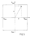
- the values A and B represent a condition of the operating signal f(t) according to the vector diagram in Fig. 5 which corresponds to phase and amplitude of a superimposed oscillation in the direct current system.
- a and B are tested in a diagnostic and determination circuit which, in the circuit diagram, is only shown for a maximum permitted value of A but is totally analogous to the minimum value of A and the minimum and maximum values of B respectively.
- the selected numerical limit values are -0,1 ⁇ A ⁇ 0,1, -0,1 ⁇ B ⁇ 0,1 respectively corresponding to 0,1 times the rated current or rated voltage.
- the threshold circuit D1 exceeds 0,1
- the presence of the transgression (the signal level) in time circuits T1, T2, T3 respectively is tested so that if A>0,1 for more than 15 ms according to T1, it is considered that an oscillation is present and an RS-flip-flop RS1 is set.
- A is then greater than 0,1 for 4 ms according to T2 and, at the same time, absent for 20 ms according to T3, the flip-flop is reset via the AND-gate G1.
- the RS-flip-flop for A>0,1 or corresponding flip-flop for any one of the other conditions are set, or any other criteria (Other Criteria) are attained, a circuit closer F is operated to apply regulating action via the OR-gates G2 and G3.
- Sustained oscillations of lower amplitude can also be monitored by, for example, selecting a level 0,02 times the rated value and a time delay of 40 ms. Oscillation within the interval 0,75-1,15 times the adjusted frequency can then be detected. This information can thereafter, possibly after an additional operational delay in order to eliminate interference, be included as "Other Criteria" according to Fig. 4.
- a and B are transmitted to an arrangement for generating a regulating signal.
- B1, B2 respectively (A ⁇ cos a - B ⁇ sin a) and (A ⁇ sin a + B ⁇ cos a) are calculated where the angle a is adjustable by means of an adjustment knob Ia.
- multiplying circuits P5, P6 respectively (A ⁇ cos a - B ⁇ sin a) is multiplied by sin ⁇ 0 t and (A ⁇ sin a + B ⁇ cos a) is multiplied by cos ⁇ 0 t from the oscillator and thereafter summarized in a summarizing circuit S3 so as to be finally multiplied in a multiplying circuit P7 with yet another normalization constant k so that the regulating signal Reg k ⁇ (A ⁇ sin( ⁇ 0 t + a) + B ⁇ cos( ⁇ 0 t + a)) is obtained.
- the delay angle a is chosen for the best damping with regard to delay due to the sampling and in the present embodiment can be selected to be 145°.
- the regulating signal Reg is, as mentioned earlier, connected to the diagnostic and determination circuit via a switch G for operating the regulating action.
- the regulating signal Reg thus has the same frequency as the resonance frequency, an amplitude determined by the disturbance's amplitude and a phase determined by the disturbance's phase, modified by the time delay of the circuit and the angle a.
- a and B denote the sin and cos component respectively of the vector, and the surrounding rectangle indicates limits for unconditionally allowable values of A and B respectively. If the amplitude of the operating signal exceeds permitted values, the vector leaves the shown rectangles and regulating action may possibly be instigated. An observed exceeding of the said limiting values does not however have to imply that a dangerous resonant oscillation has arisen, but instead it may be that a normal course of events can have been recognized as coincidental amplitudes at a resonant frequency.
- Oscillation at a frequency which is somewhat different from the resonant frequency will appear in the indicator diagram as a vector which rotates with a speed determined by the difference in frequency between the oscillator frequency (i.e. the selected resonant frequency) and the oscillation in question. Due to the said conditions, such an oscillation will not initiate any regulating action. Should, however, the vector remain stationary or rotate slowly, an oscillation with the same or similar frequency as the reference signal is present and resonance must be seen to be present and consequently a regulating action will be initiated.
- the preferably temporary regulating action (which according to the above in certain cases can be permanent) according to the invention can be initiated in the normal regulating of the HVDC-system which regulates the firing moments for included controlled rectifiers.
- the normal control equipment adjusts the firing moments to a certain firing angle ⁇ , calculated in each rectifier part from the lead current's positive zero crossings. It is suitable to let the regulating signal according to the invention, with by-pass connection of the normal regulating, directly influence the firing angle ⁇ , whereby necessarily rapid damping is advantageously obtained.
- the described principle for detection and damping of transient oscillations can also be used for those oscillations which arise in alternating current networks and have low frequencies in relation to the system frequency.
- An example of this is shown schematically in Fig. 6 and in which some of the same reference numerals as in Fig. 1 are used.
- Two turbine plants 100 with generators 110 are connected to a three-phase network which is also connected to an HVDC-network.
- the regulator circuit R in the alternating current network is examined in order to determine in a corresponding manner as given above possible resonant oscillations at subsynchronous frequencies.
- Current voltage in a phase conductor is suitably used as a variable and the regulating action REG is transmitted to the rectifier arrangement 10.
- the regulating signal can be transmitted to a control circuit of the generator G. Since in this case a number of possible oscillating frequencies (inherent values) can arise, each of these should be monitored.
- a particular advantage with the invention is that its action need only be as temporary as the disturbances which it is intended to eliminate, thereby implying that the regular control is disturbed as little as possible.
- a further particular advantage is that with detection and damping of oscillation carried out according to the invention, oscillations which do not totally lie at the selected frequency of the reference signal can also be effectively detected and dampened.
Landscapes
- Engineering & Computer Science (AREA)
- Power Engineering (AREA)
- Control Of Eletrric Generators (AREA)
- Supply And Distribution Of Alternating Current (AREA)
- Measurement Of Mechanical Vibrations Or Ultrasonic Waves (AREA)
- Force Measurement Appropriate To Specific Purposes (AREA)
- Control Of Transmission Device (AREA)
- Train Traffic Observation, Control, And Security (AREA)
- Crushing And Grinding (AREA)
- Measurement Of Resistance Or Impedance (AREA)
Claims (14)
- Verfahren zur Dämpfung von Schwingungen bei oder nahe einer Eigenresonanzfrequenz in einem Starkstromübertagungssystem, gekennzeichnet durch- Schritte zur Gewinnung eines Referenzsignals (R) von einem Oszillator (Osc), der mit der Eigenresonanzfrequenz schwingt;- Multiplikation des Referenzsignals (R) mit einem analogen Betriebssignal (f(t)), welches der herrschenden Betriebsbedingung an einem Punkt in dem Starkstromübertagungssystem entspricht;- Einzelwertabtastung (sampling) des sich aus der Multiplikation ergebenden analogen Signals mit einer Abtastfrequenz (ωs), die mindestens doppelt so groß wie die Frequenz des Referenzsignals (R) ist;- fortlaufende Speicherung der digitalen Abtastwerte in einem Speicher bis zu einer Anzahl, die mindestens der Periode des Referenzsignals entspricht;- anschließende Berechnung für jeden Abtastaugenblick der Summe einer Anzahl (n) der letzten Abtastwerte, die einer oder mehreren vollständigen Perioden des Referenzsignals entspricht, wobei die Summe den Phasenwinkel und die Amplitude einer Schwingung im Betriebssignal repräsentiert;- Prüfung der Summe in mindestens einem Diagnostik- und Bestimmungsglied (Diag) zur Feststellung von Schwingungen gemäß vorbestimmten Kriterien und zur Bestimmung der Aktivierung eines Regeleingriffes;- Berechnung eines Regelsignals (Reg) für jeden Abtastaugenblick in Abhängigkeit der charakteristischen Summe für die Schwingung und in Abhängigkeit des Referenzsignals (R) sowie, falls die Schwingung irgendeines der vorbestimmten Kriterien erfüllt, Übertragung des Regelsignals (Reg) an eine Regelanordnung in dem Starkstromübertagungssystem derart, daß die Schwingung auf vorbestimmte Toleranzen gedämpft wird.
- Verfahren nach Anspruch 1, dadurch gekennzeichnet, daß das genannte Referenzsignal (R) aus zwei Komponenten besteht, die R1=sin(ωot) und R2=cos(ωot) entsprechen, und daß jedes der Referenzsignale R1 und R2 mit einem Betriebssignal f(t) multipliziert wird und zu einem Signal a(t) beziehungsweise b(t) wird.
- Verfahren nach Anspruch 1 oder 2, dadurch gekennzeichnet, daß die Signale a(t) und b(t) in Form von diskreten Werten mit der genannten Abtastfrequenz (ωs) abgetastet werden und daß die Abtastwerte (a beziehungsweise b) in einem Speicher gespeichert werden.
- Verfahren nach einem der Ansprüche 1 bis 3, dadurch gekennzeichnet, daß zwei Sätze von Abtastwerten (A1..An beziehungsweise B1..Bn) der genannten Anzahl (n) jeweils zu ihrem resultierenden Wert (A beziehungsweise B) summiert werden, die zusammen eine Bedingung für das genannte Betriebssignal (f(t)) in jedem Abtastaugenblick darstellen.
- Verfahren nach Anspruch 4, dadurch gekennzeichnet, daß die resultierenden Werte (A und B) in mindestens einem Diagnostik- und Bestimmungsglied (Diag) geprüft werden zur Feststellung von Schwingungen mit unterschiedlichen Charakteristika, zum Beispiel Schwingungen mit einer oder mehreren kritischen Frequenzen, Schwingungen mit relativ hoher Frequenzen und Amplitude und/oder andauernde Schwingungen mit relativ niedriger Frequenz und Amplitude oder anderen vorbestimmten Kriterien.
- Verfahren gemäß Anspruch 5, dadurch gekennzeichnet, daß, wenn die genannten resultierenden Werte (A beziehungsweise B) fortdauernd bestimmte Werte übersteigen oder unter bestimmten Werten liegen, die der Größe der Amplitude einer Schwingung entsprechen, das genannte Regelsignal (Reg) der genannten Regelanordnung zugeführt wird.
- Verfahren nach Anspruch 5 oder 6, dadurch gekennzeichnet, daß das Regelsignal (Reg) gewonnen wird mit Hilfe der genannten resultierenden Werte (A beziehungsweise B) und von dem Oszillatorsignal und sin a beziehungsweise cos a abhängig ist, wobei a ein geeigneter Wert für den Regeleingriff ist, wobei- Signale, die (A-cos a - B-sin a) beziehungsweise (A-sin a - B-cos a) entsprechen, erzeugt werden,- jedes der oben genannten Signale, die (A-cos a - B-sin a) beziehungsweise (A-sin a + B-cos a) entsprechen, mit Komponenten R1=sin(ωot) beziehungsweise R2=cos(ωot) der erstgenannten Schwingung (Osc) multipliziert werden,- die Produkte (sin(ωot)-(A-cos a - B-sin a)) beziehungsweise (cos(ωot)-(A-sin a + B-cos a) derart summiert werden, daß das Regelsignal (Reg) (A-sin(ωo + a) + B-cosωo + a)) entspricht.
- Verfahren nach Anspruch 7, dadurch gekennzeichnet, daß der obengenannte Winkel a einstellbar ist.
- Verfahren nach einem der vorhergehenden Ansprüche, dadurch gekennzeichnet, daß das Regelsignal (Reg) einer Regelanordnung in einem statischen Stromrichter in einem HGÜ-System zugeführt wird.
- Verfahren nach einem der Ansprüche 1 bis 8, dadurch gekennzeichnet, daß das Regelsignal (Reg) einem Generatorsteuerglied für einen Turbinengenerator (110) zugeführt wird.
- Verfahren nach einem der vorhergehenden Ansprüche, dadurch gekennzeichnet, daß der Grad der Verstärkung der Regelung einstellbar ist und daß es in Abhängigkeit der Größe der festgestellten Schwingung eingestellt wird.
- Anordnung zur Dämpfung von Schwingungen bei oder nahe einer Eigenresonanzfrequenz in einem Starkstromübertagungssystem, gekennzeichnet durch- einen Oszillator (Osc), der ein Referenzsignal (R) abzugeben vermag, welches mit der Eigenresonanzfrequenz schwingt,- ein Multiplikationsglied (TT) zur Multiplikation eines Betriebssignals (f(t)), welches der herrschenden Betriebsbedingung der HGÜ-Systems entspricht, mit dem Referenzsignal (R);- ein Speicher (M) und ein Uhrenimpulsgenerator (CPG) zur seriellen Erfassung diskreter Werte des Ausgangssignals des Multiplikationsgliedes (TT) mittels von Uhrenimpulsen (CP);- Die Fähigkeit des Speichers (M), die Abtastwerte bis zu einer Anzahl (N) zu speichern, die zumindest einer Periode des Referenzsignals (R) entspricht;- ein Summierungsglied (Σ) zur Summierung, über einen parallelen Ausgang des Speichers (M), einer Anzahl (N) der letzten Abtastwerte, die eine oder mehreren ganzen Perioden des Referenzsignals (R) entsprechen;- ein Diagnostik- und Bestimmungsglied (Diag) zum Empfang des Ausgangssignals von dem Summierungsglied (Σ), in welchem Glied (Diag) die Größe, das Vorzeichen, die Veränderlichkeit und die Anwesenheit eines Ausgangssignals vom Summierungsglied (Σ) gemäß vorbestimmten Kriterien geprüft wird;- eine Anordnung zur Erzeugung eines Regelsignals (Reg) und zum Empfang des Ausgangssignals von dem Summierungsglied (Σ), und durch- eine Schalteranordnung (F), die von dem Ausgangssignal des Diagnostik- und Bestimmungsglied (Diag) aktiviert werden kann, wenn ein Kriterium für eine Schwingung, die gedämpft werden soll, erfüllt ist, welche Schalteranordnung zwischen dem Ausgang der Anordnung zur Erzeugung eines Regelsignals (Reg) und einer Regeleinrichtung in dem Starkstromübertagungssystem angeordnet ist.
- Anordnung nach Anspruch 12, dadurch gekennzeichnet, daß der genannte Speicher (M) ein Schieberegister (M1, M2) ist.
- Anordnung nach Anspruch 12 oder 13, dadurch gekennzeichnet, daß eine Einrichtung (P7) zur Regelung der Verstärkung des Regelsignals in Abhängigkeit von der Größe des geprüften Signals vorhanden ist.
Applications Claiming Priority (3)
| Application Number | Priority Date | Filing Date | Title |
|---|---|---|---|
| SE9202654 | 1992-09-15 | ||
| SE9202654A SE500683C2 (sv) | 1992-09-15 | 1992-09-15 | Sätt och anordning för detektering och dämpning av svängningar vid eller nära en resonansbenägen frekvens i ett kraftöverföringssystem |
| PCT/SE1993/000747 WO1994007291A1 (en) | 1992-09-15 | 1993-09-15 | Method and arrangement for detecting and damping transient oscillations at or near a natural resonant frequency in a power transmission system |
Publications (2)
| Publication Number | Publication Date |
|---|---|
| EP0671067A1 EP0671067A1 (de) | 1995-09-13 |
| EP0671067B1 true EP0671067B1 (de) | 1996-11-20 |
Family
ID=20387177
Family Applications (1)
| Application Number | Title | Priority Date | Filing Date |
|---|---|---|---|
| EP93921149A Expired - Lifetime EP0671067B1 (de) | 1992-09-15 | 1993-09-15 | Verfahren und vorrichtung zur detektion und dämpfung von transienten schwingungen mit einer eigenfrequenz oder in der nähe derselbigen für ein system zur energieübertragung |
Country Status (6)
| Country | Link |
|---|---|
| US (1) | US5677852A (de) |
| EP (1) | EP0671067B1 (de) |
| JP (1) | JPH08501439A (de) |
| DE (1) | DE69306127T2 (de) |
| SE (1) | SE500683C2 (de) |
| WO (1) | WO1994007291A1 (de) |
Families Citing this family (15)
| Publication number | Priority date | Publication date | Assignee | Title |
|---|---|---|---|---|
| SE503374C2 (sv) * | 1994-11-15 | 1996-06-03 | Asea Brown Boveri | Förfarande och anordning för styrning av en i en anläggning för överföring av högspänd likström ingående seriekompenserad strömriktarstation |
| DE69839839D1 (de) * | 1998-03-23 | 2008-09-18 | Abb Ab | Dämpfung von Schwingungen in einer Anlage zur Übertragung von Hochspannungsgleichstrom |
| DE10059331A1 (de) * | 2000-11-29 | 2002-06-13 | Siemens Ag | Verringerung von Systemeigenschwingungen bei einem an einem Umrichter mit Spannungszwischenkreis betriebenen elektrischen Motor durch periodisches Abkoppeln des Zwischenkreises vom Netz sowie korrespondierender Spannungszwischenkreis-Umrichter |
| US6774614B2 (en) | 2002-02-27 | 2004-08-10 | General Electric Company | Method and apparatus for detecting current |
| DE102004011551A1 (de) * | 2004-03-08 | 2005-09-29 | A. Eberle Gmbh | Einrichtung zur Prävention von Großstörungen in elektrischen Versorgungsnetzen |
| CN102148492B (zh) * | 2010-12-21 | 2014-08-27 | 中国电力科学研究院 | 一种次同步振荡抑制和保护装置控制输入信号的获取方法 |
| KR20150130862A (ko) * | 2014-05-14 | 2015-11-24 | 엘에스산전 주식회사 | 고압 직류 송전 시스템 및 그의 제어 방법 |
| CN104392140B (zh) * | 2014-12-04 | 2017-05-17 | 北京四方继保自动化股份有限公司 | 一种环境激励下发电机组轴系扭振模态参数的辨识方法 |
| EP3070799B1 (de) * | 2015-03-16 | 2018-11-21 | General Electric Technology GmbH | Inbetriebsetzung von hvdc-netzwerken |
| EP3070827B1 (de) * | 2015-03-16 | 2022-09-07 | General Electric Technology GmbH | Inbetriebsetzung von hvdc-netzwerken |
| KR101980685B1 (ko) * | 2015-07-09 | 2019-05-22 | 엘에스산전 주식회사 | 전력 계통 해석 장치 및 전력 계통 해석 방법 |
| JP6831037B2 (ja) * | 2017-08-03 | 2021-02-17 | アー・ベー・ベー・パワー・グリッズ・スウィツァーランド・アクチェンゲゼルシャフトAbb Power Grids Switzerland Ag | Dcシステムにおいて電圧源変換器を制御すること |
| US10983150B2 (en) | 2017-08-28 | 2021-04-20 | General Electric Technology Gmbh | Systems and methods for detecting and evaluating oscillations in an electrical power grid |
| DE102018120768A1 (de) | 2018-08-24 | 2020-02-27 | Wobben Properties Gmbh | Windenergieanlage und Verfahren zum Erkennen niederfrequenter Schwingungen in einem elektrischen Versorgungsnetz |
| DE102019219857A1 (de) * | 2019-12-17 | 2021-06-17 | Siemens Aktiengesellschaft | Verfahren zur Vermessung des Schwingungsverhaltens eines Antriebsstrangs eines einen Generator aufweisenden Turbosatzes eines mit einem Energienetz verbundenen Kraftwerks |
Family Cites Families (11)
| Publication number | Priority date | Publication date | Assignee | Title |
|---|---|---|---|---|
| US4434376A (en) * | 1979-07-23 | 1984-02-28 | Electric Power Research Institute, Inc. | Method and means for damping subsynchronous oscillations and DC offset in an AC power system |
| CH659742A5 (de) * | 1983-04-08 | 1987-02-13 | Bbc Brown Boveri & Cie | Schaltungsanordnung zur erhoehung der stabilitaet in einem von einem generator gespeisten drehstromnetz. |
| US4724333A (en) * | 1985-04-10 | 1988-02-09 | Electric Power Research Institute | Method and means for damping supersynchronous oscillations in an ac power system |
| US4788653A (en) * | 1986-12-23 | 1988-11-29 | General Electric Company | Digital filter for power system stabilizer |
| DE58904574D1 (de) * | 1988-03-15 | 1993-07-08 | Siemens Ag | Verfahren zur stabilisierung eines schwingungsfaehigen elektrischen versorgungsnetzes. |
| US4855664A (en) * | 1988-06-10 | 1989-08-08 | General Electric Company | Method and apparatus for damping oscillations of an ac generator |
| CA1316980C (en) * | 1988-12-27 | 1993-04-27 | Daniel C. Hughey | Power supply |
| DE3905261A1 (de) * | 1989-02-21 | 1990-08-23 | Siemens Ag | Verfahren und einrichtung zur stabilisation eines elektrischen versorgungsnetzes |
| US4999564A (en) * | 1989-10-12 | 1991-03-12 | General Electric Company | Power system stabilizer system having improved integrity checking scheme |
| US5398150A (en) * | 1992-03-09 | 1995-03-14 | Dehn & Soehne Gmbh | Coordinated electric surge suppressor with means for suppressing oscillatory transient overvoltages |
| US5426579A (en) * | 1993-07-28 | 1995-06-20 | Best Power Technology, Incorporated | Method and apparatus for stabilizing AC power supply systems connected to power factor correcting loads |
-
1992
- 1992-09-15 SE SE9202654A patent/SE500683C2/sv not_active IP Right Cessation
-
1993
- 1993-09-15 WO PCT/SE1993/000747 patent/WO1994007291A1/en not_active Ceased
- 1993-09-15 US US08/397,173 patent/US5677852A/en not_active Expired - Lifetime
- 1993-09-15 EP EP93921149A patent/EP0671067B1/de not_active Expired - Lifetime
- 1993-09-15 JP JP6508011A patent/JPH08501439A/ja active Pending
- 1993-09-15 DE DE69306127T patent/DE69306127T2/de not_active Expired - Fee Related
Also Published As
| Publication number | Publication date |
|---|---|
| DE69306127D1 (de) | 1997-01-02 |
| WO1994007291A1 (en) | 1994-03-31 |
| SE9202654D0 (sv) | 1992-09-15 |
| SE9202654L (sv) | 1994-03-16 |
| SE500683C2 (sv) | 1994-08-08 |
| EP0671067A1 (de) | 1995-09-13 |
| DE69306127T2 (de) | 1997-06-12 |
| US5677852A (en) | 1997-10-14 |
| JPH08501439A (ja) | 1996-02-13 |
Similar Documents
| Publication | Publication Date | Title |
|---|---|---|
| EP0671067B1 (de) | Verfahren und vorrichtung zur detektion und dämpfung von transienten schwingungen mit einer eigenfrequenz oder in der nähe derselbigen für ein system zur energieübertragung | |
| US4080559A (en) | Torsional protective device for power system stabilizer | |
| US5805395A (en) | Half-cycle summation V/Hz relay for generator and transformer over-excitation protection | |
| RU2263925C2 (ru) | Устройство и способ обнаружения короткого замыкания на землю и вычисления его сопротивления | |
| US7521822B2 (en) | Protection techniques for a back-up electric power system | |
| KR830000301B1 (ko) | 보호 계전 장치 | |
| US20090079436A1 (en) | Method and apparatus for generalized ac and dc arc fault detection and protection | |
| Xia et al. | A new method based on artificial neural network, wavelet transform and short time Fourier transform for subsynchronous resonance detection | |
| US11355912B2 (en) | Method and device for detecting faults in transmission and distribution systems | |
| EP3872502A1 (de) | Verfahren und vorrichtung zur detektion von untersynchronen schwingungen in einem leistungssystem | |
| US5198745A (en) | Dynamic braking resistor system | |
| JPH11514834A (ja) | 波形歪みのソース判別回路および方法 | |
| US4219768A (en) | Method for regulating the voltage of an electric generator and a system for the application of said method | |
| EP0657991B1 (de) | Signalerfassungsschaltung für digitale Regelung | |
| US5438253A (en) | Static var generator using self-commutated inverter | |
| EP0637865A2 (de) | Differentialrelais für Transformator | |
| KR830001530B1 (ko) | 보호 계전기 장치 | |
| US20110102952A1 (en) | Method for production of an oscillating signal and of an electrical protection device or measurement instrument having an oscillation identification device | |
| JP3184812B2 (ja) | 直流送電制御装置 | |
| JP2001268802A (ja) | 分散型電源の系統連系保護方法およびその装置 | |
| US7206177B2 (en) | Device and method for protection against overcurrents in an electrical energy distribution cabinet | |
| US20180123346A1 (en) | Detection and mitigation of instability of synchronous machines | |
| US11050262B1 (en) | Systems and methods for controlling electrical grid resources | |
| EP0945957A1 (de) | Dämpfung von Schwingungen in einer Anlage zur Übertragung von Hochspannungsgleichstrom | |
| JPH0698469A (ja) | 電圧検出形無効電力補償装置の制御方式 |
Legal Events
| Date | Code | Title | Description |
|---|---|---|---|
| PUAI | Public reference made under article 153(3) epc to a published international application that has entered the european phase |
Free format text: ORIGINAL CODE: 0009012 |
|
| 17P | Request for examination filed |
Effective date: 19950224 |
|
| AK | Designated contracting states |
Kind code of ref document: A1 Designated state(s): CH DE FR GB IT LI SE |
|
| GRAG | Despatch of communication of intention to grant |
Free format text: ORIGINAL CODE: EPIDOS AGRA |
|
| 17Q | First examination report despatched |
Effective date: 19960214 |
|
| GRAH | Despatch of communication of intention to grant a patent |
Free format text: ORIGINAL CODE: EPIDOS IGRA |
|
| GRAH | Despatch of communication of intention to grant a patent |
Free format text: ORIGINAL CODE: EPIDOS IGRA |
|
| GRAA | (expected) grant |
Free format text: ORIGINAL CODE: 0009210 |
|
| AK | Designated contracting states |
Kind code of ref document: B1 Designated state(s): CH DE FR GB IT LI SE |
|
| PG25 | Lapsed in a contracting state [announced via postgrant information from national office to epo] |
Ref country code: LI Effective date: 19961120 Ref country code: CH Effective date: 19961120 |
|
| REF | Corresponds to: |
Ref document number: 69306127 Country of ref document: DE Date of ref document: 19970102 |
|
| ET | Fr: translation filed | ||
| ITF | It: translation for a ep patent filed | ||
| PG25 | Lapsed in a contracting state [announced via postgrant information from national office to epo] |
Ref country code: SE Effective date: 19970220 |
|
| REG | Reference to a national code |
Ref country code: CH Ref legal event code: PL |
|
| PLBE | No opposition filed within time limit |
Free format text: ORIGINAL CODE: 0009261 |
|
| STAA | Information on the status of an ep patent application or granted ep patent |
Free format text: STATUS: NO OPPOSITION FILED WITHIN TIME LIMIT |
|
| 26N | No opposition filed | ||
| REG | Reference to a national code |
Ref country code: GB Ref legal event code: IF02 |
|
| PGFP | Annual fee paid to national office [announced via postgrant information from national office to epo] |
Ref country code: FR Payment date: 20030909 Year of fee payment: 11 |
|
| PGFP | Annual fee paid to national office [announced via postgrant information from national office to epo] |
Ref country code: GB Payment date: 20030910 Year of fee payment: 11 |
|
| PGFP | Annual fee paid to national office [announced via postgrant information from national office to epo] |
Ref country code: DE Payment date: 20030925 Year of fee payment: 11 |
|
| PG25 | Lapsed in a contracting state [announced via postgrant information from national office to epo] |
Ref country code: GB Free format text: LAPSE BECAUSE OF NON-PAYMENT OF DUE FEES Effective date: 20040915 |
|
| PG25 | Lapsed in a contracting state [announced via postgrant information from national office to epo] |
Ref country code: DE Free format text: LAPSE BECAUSE OF NON-PAYMENT OF DUE FEES Effective date: 20050401 |
|
| GBPC | Gb: european patent ceased through non-payment of renewal fee |
Effective date: 20040915 |
|
| PG25 | Lapsed in a contracting state [announced via postgrant information from national office to epo] |
Ref country code: FR Free format text: LAPSE BECAUSE OF NON-PAYMENT OF DUE FEES Effective date: 20050531 |
|
| REG | Reference to a national code |
Ref country code: FR Ref legal event code: ST |
|
| PGFP | Annual fee paid to national office [announced via postgrant information from national office to epo] |
Ref country code: IT Payment date: 20060930 Year of fee payment: 14 |
|
| PG25 | Lapsed in a contracting state [announced via postgrant information from national office to epo] |
Ref country code: IT Free format text: LAPSE BECAUSE OF NON-PAYMENT OF DUE FEES Effective date: 20070915 |